Week 6: Electronic Design
Week 6: Electronic Design
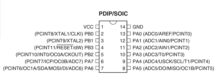
We use a multimeter to measure the continuity and identify what pins belong to the pinHeaders of a board provided by the laboratory. To do this we identify the MIU and look for its data sheet, then we measure continuity between the pinHeaders and the microcontroller pins.
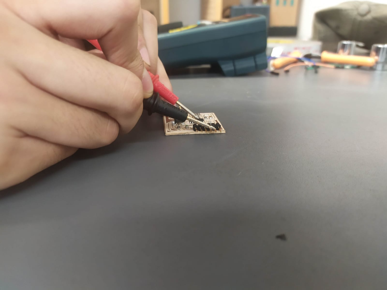
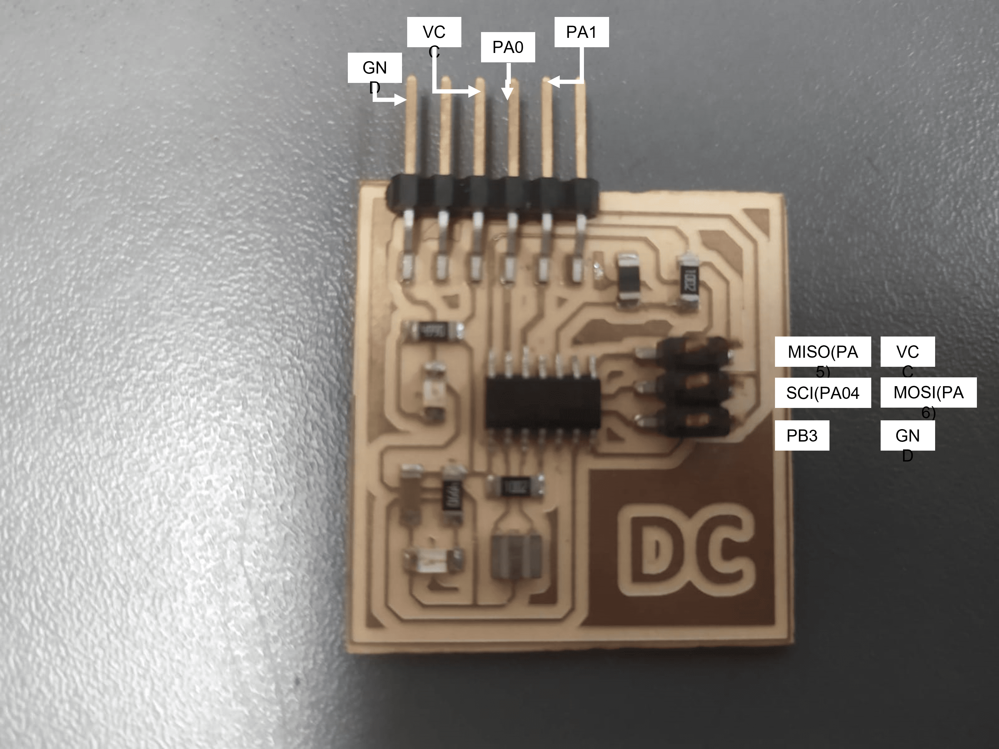
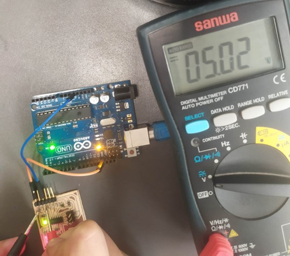
It was also verified that the working voltage of the electronic board is 5V.
We also use the oscilloscope to measure the behavior of the voltage in a potentiometer and an LDR:
We also use the oscilloscope to measure the behavior of the voltage in a potentiometer and an LDR:
Potentiometer: It is observed that the voltage varies based on the position of the potentiometer, this is a variable resistor.
LDR: It is observed that it varies based on the amount of light.
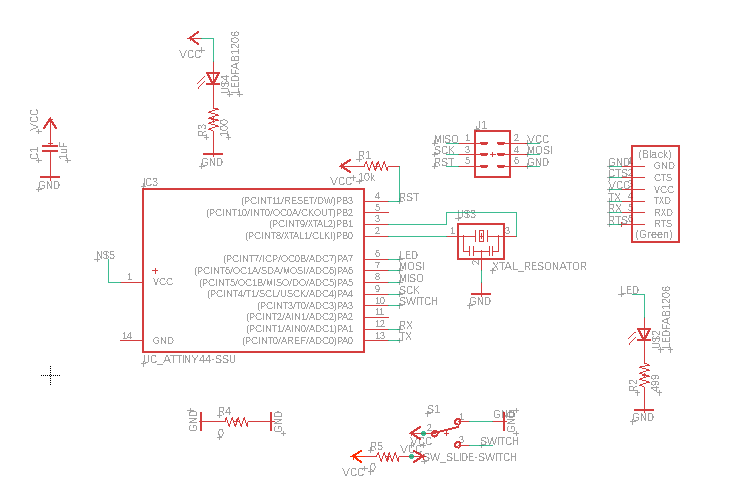
I decided to use Eagle as electronic design software. Autodesk Eagle is an electronic design software (EDA) used to create electronic circuit schematics and PCB (printed circuit board) layouts. The software allows users to design circuit schematics, design printed circuit boards, and generate Gerber files for further manufacturing.
The fab library was downloaded where the components required for the design were found.
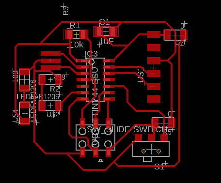
Here you make the electronic schematic, add the components and link them to create the logic of your circuit.
It is the representation of your electronic schematic simulating the dimensions and tracks of the components and their final positions.
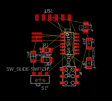
I tried to route with the autorouter option, but the design required jumpers to connect properly, so I had to do it by hand and add two 0 ohm resistors as jumpers.
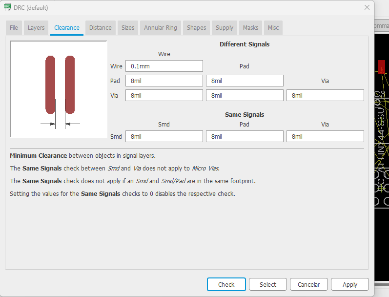
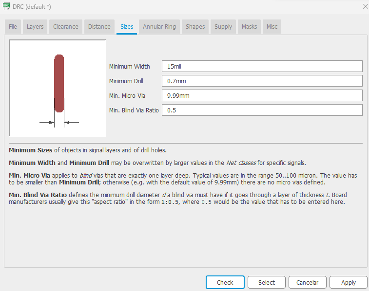
Here are the parameters of the DRC (Design Rules Check) that I chose, using this tool we make sure that the manufacturing is done correctly.
The DRC indicates the paths to correct:
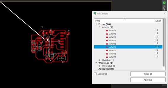
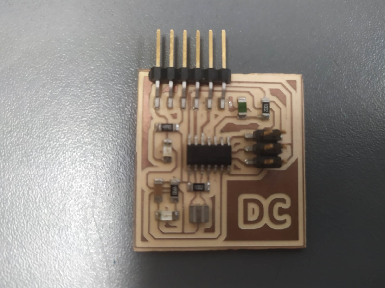
Once the errors have been corrected, the board is ready to be manufactured.