Week 3: Computer-Controller Cutting
Week 3: Computer-Controller Cutting
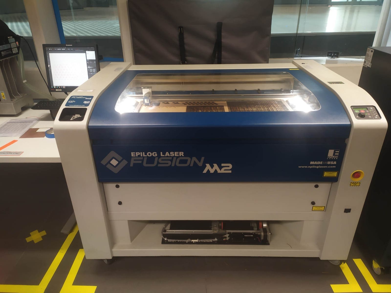
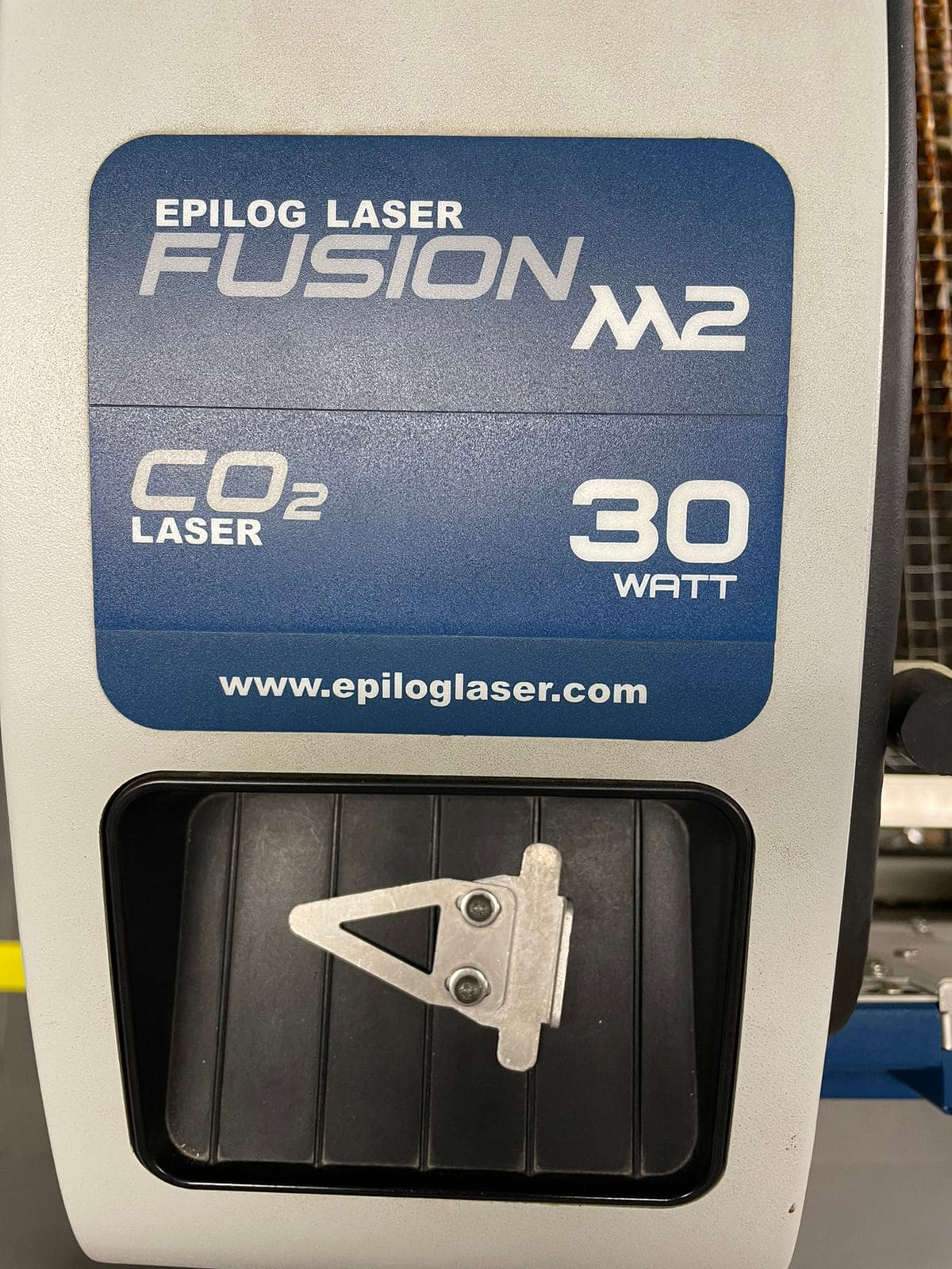
This week is divided into 2 tasks, the group one that consists of performing speed, power, kerf and rate tests. The individual task is to cut something on the vinylcutter and make a parametric construction kit that includes the previously found kerf. The laser cutter model that the laboratory has is Epilog laser fusion m2 of 30 watts and has a work area of 1000mm * 700mm.
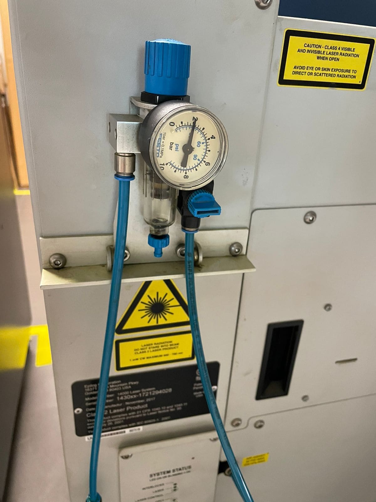
Next to the laser cutter is the extractor, whose function is to suck and filter the gases that are generated when working with the material. This must always be turned on before starting to cut the material.
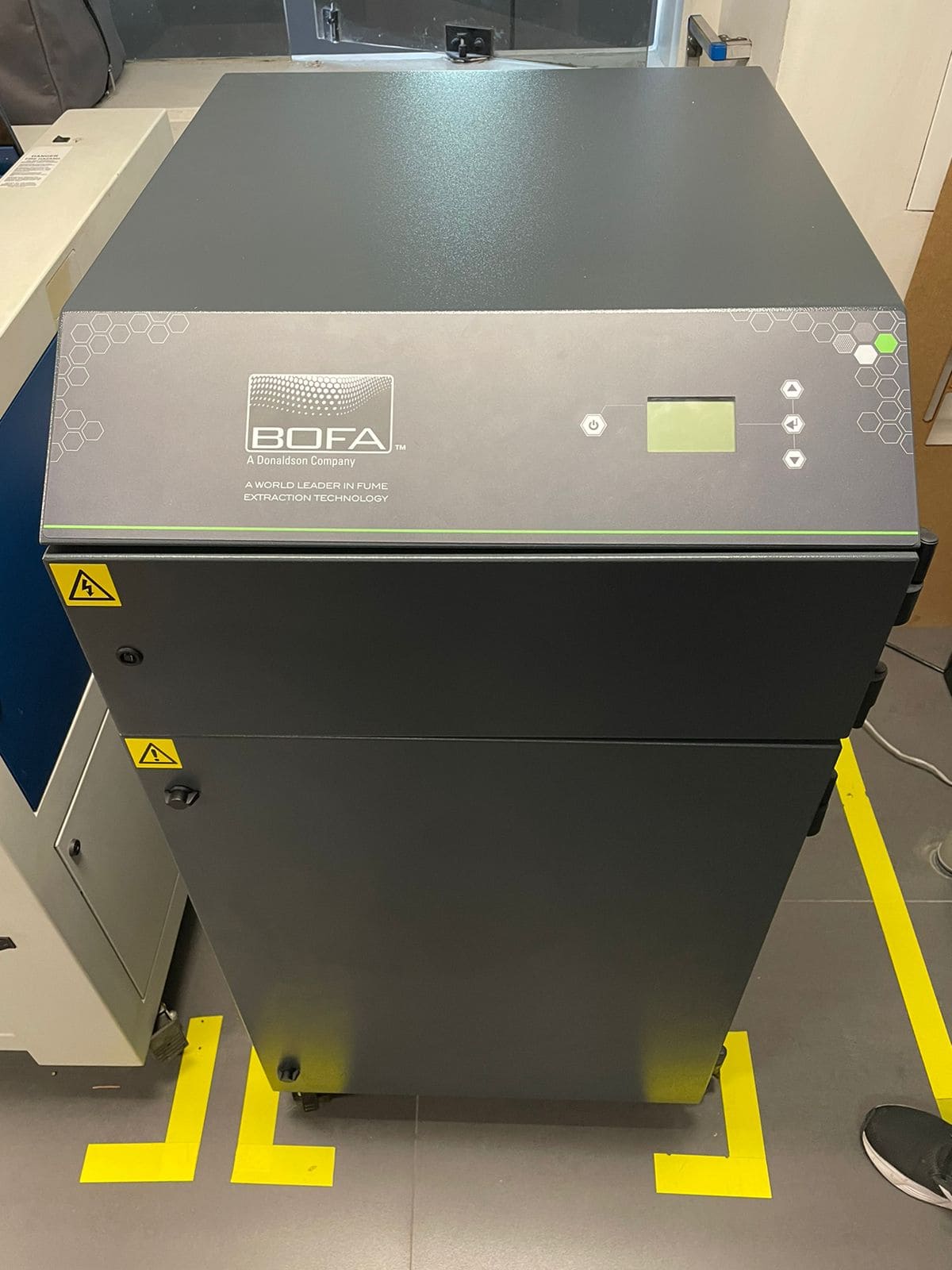
Always check that the valve on the back of the laser cutter is activated and that there is airflow.
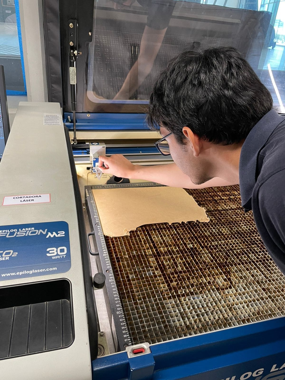
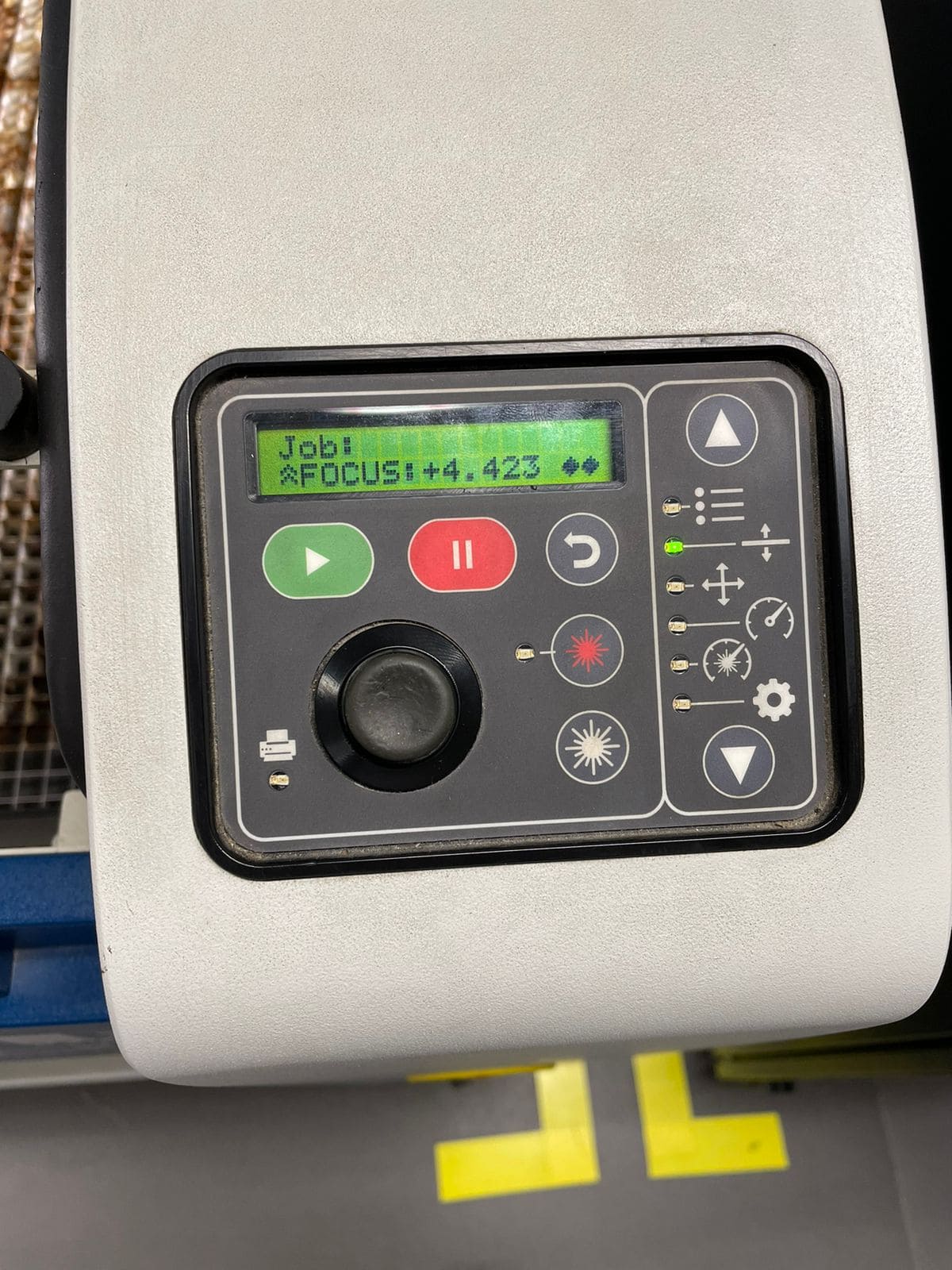
The calibration of the axes is also important, these are done on the laser screen. In the case of the Z axis, it is necessary to use a calibration tool that is placed in the laser and the joystick is moved until the tool touches the material, then press the joystick to set the axis.
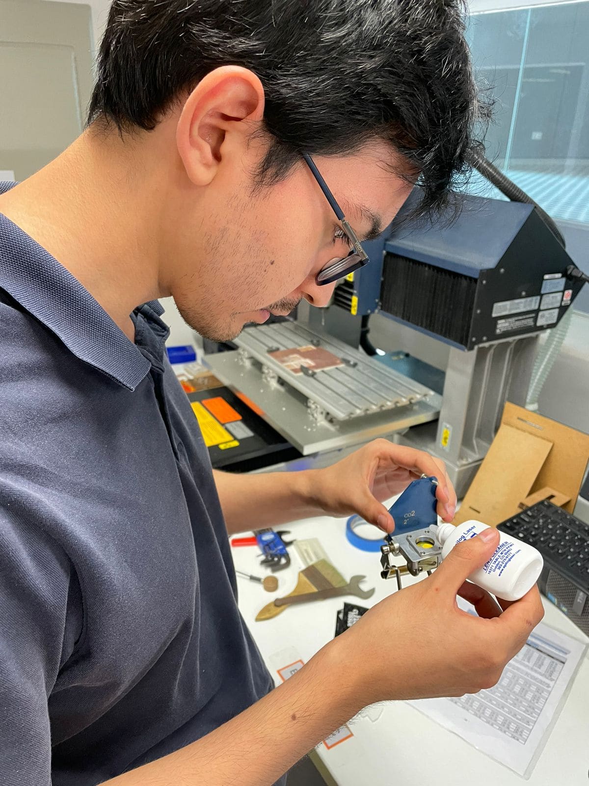
the lens tends to get dirty with the particles that come off when cutting, so cleaning the lens is important. The lens is removed from the machine and a drop of a special liquid is applied to each face, then cleaned with a special piece of paper.
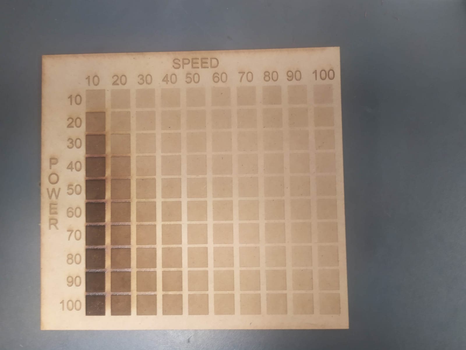
The first material I used was MDF, using a test palette and varying the power and speed we can appreciate the final result of different combinations of parameters.
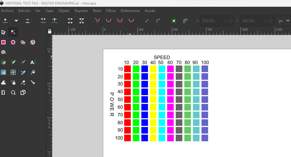
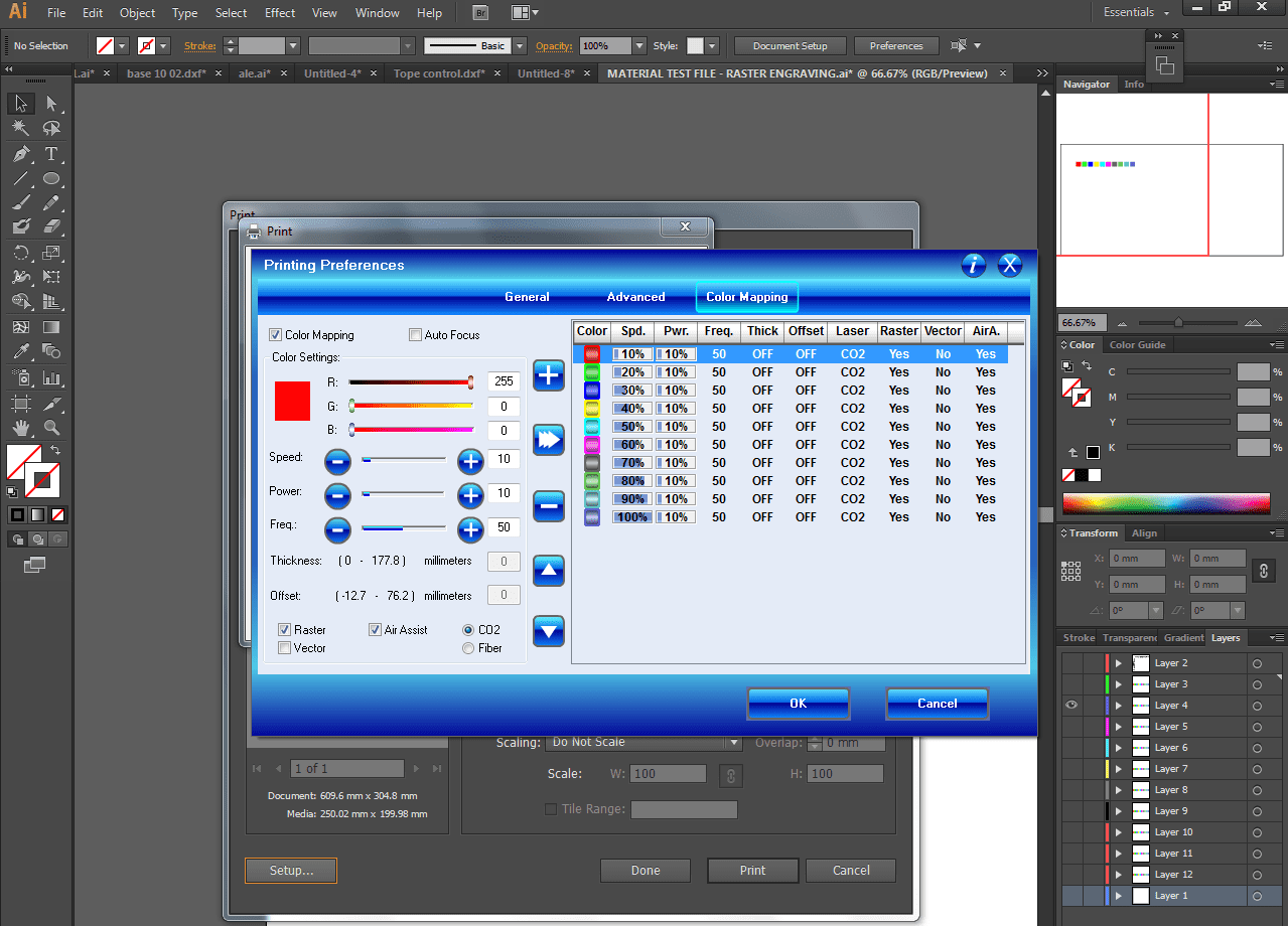
For this, the design was exported in DXF format and the required parameters were applied, to achieve the combinations that is show in the palette, the Color mapping option was used to apply different speeds based on RGB color and the rows were separated into layers to engrave at different powers.
This video shows how the laser performs the engraving on the material.
This is the final result
Kerf is the material that the laser beam removes while cutting, to achieve a proper fit it is required to design taking kerf into account as a parameter. To do this, we proceeded to find the kerf of the machine. This varies depending on the material, power and speed, so it was decided to take a sample of 10 parts of 5 mm x 30 mm and find the average kerf under the recommended MDF cutting parameters provided by the supplier. The design was made in autodesk inventor, it consists of 10 and the sketch was exported in dxf format
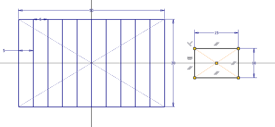
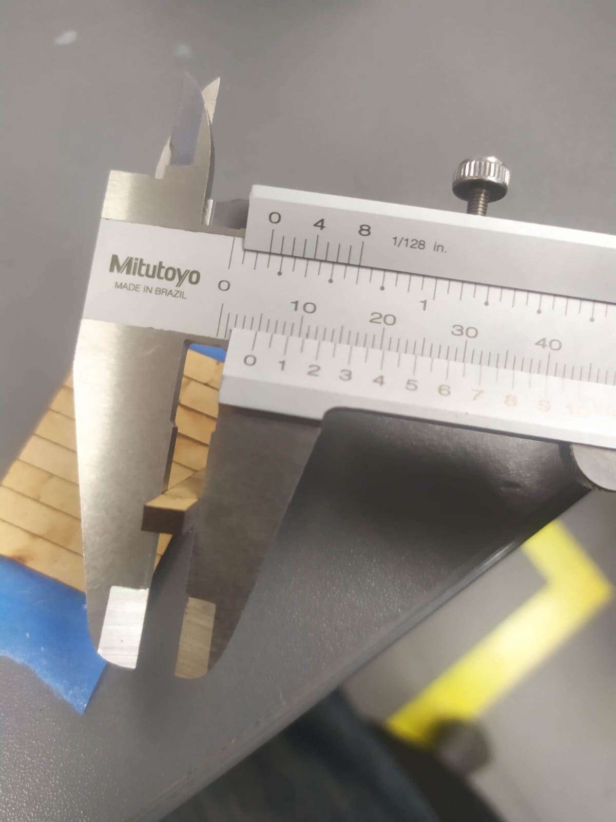
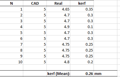
A vernier was used to measure the length of the rectangles and subtract it from the length of the design. (Example: 5mm - 4.8mm = 0.2mm).
With the 10 kerfs calculated, the average is found, resulting in 0.26 mm.
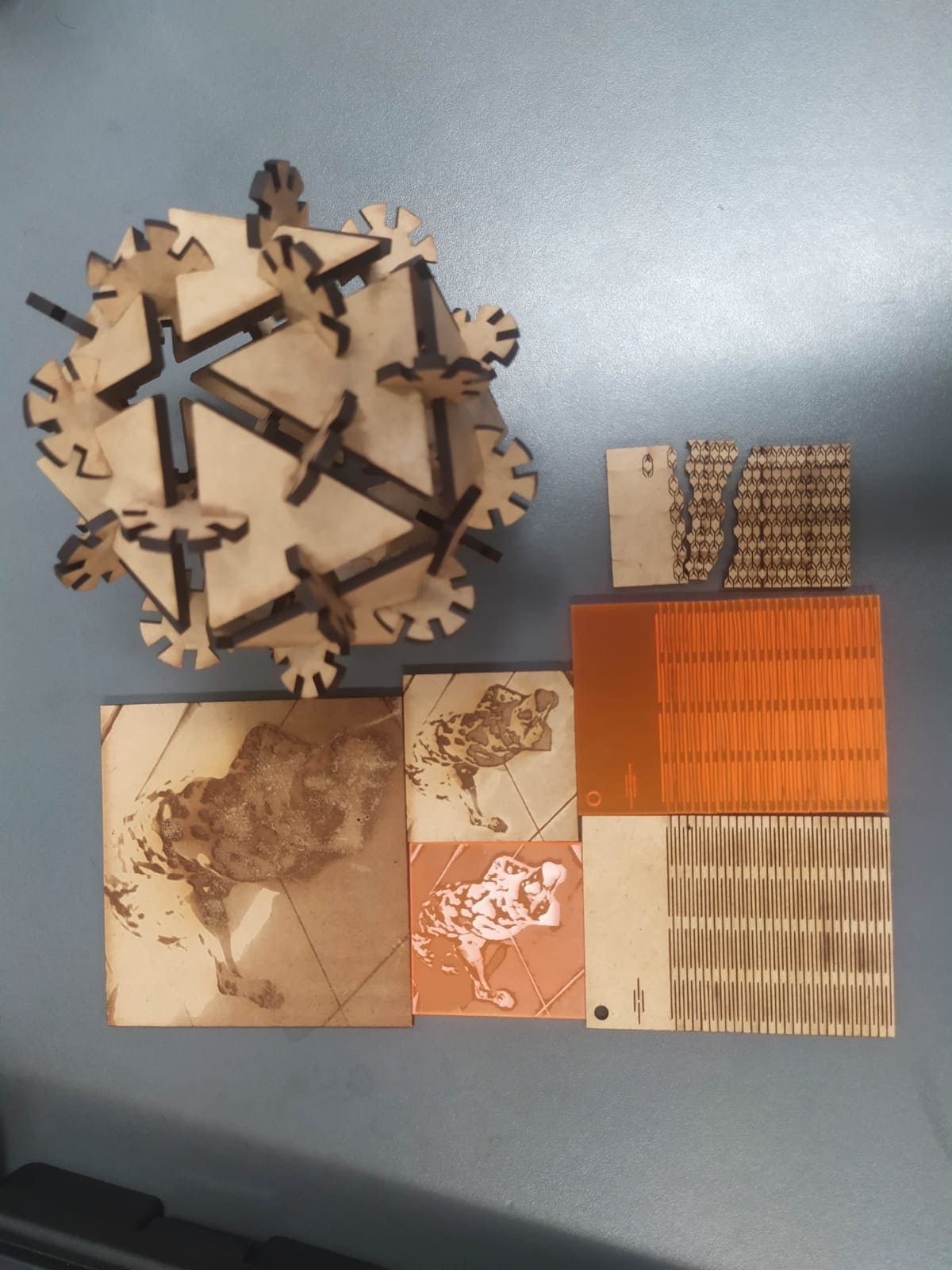
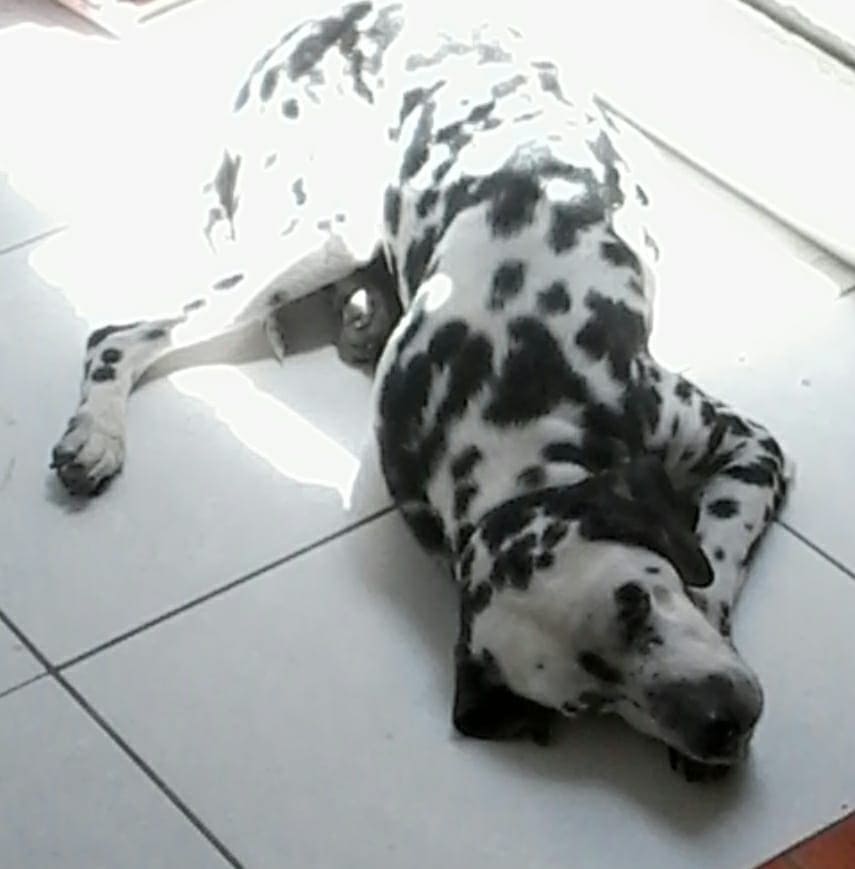
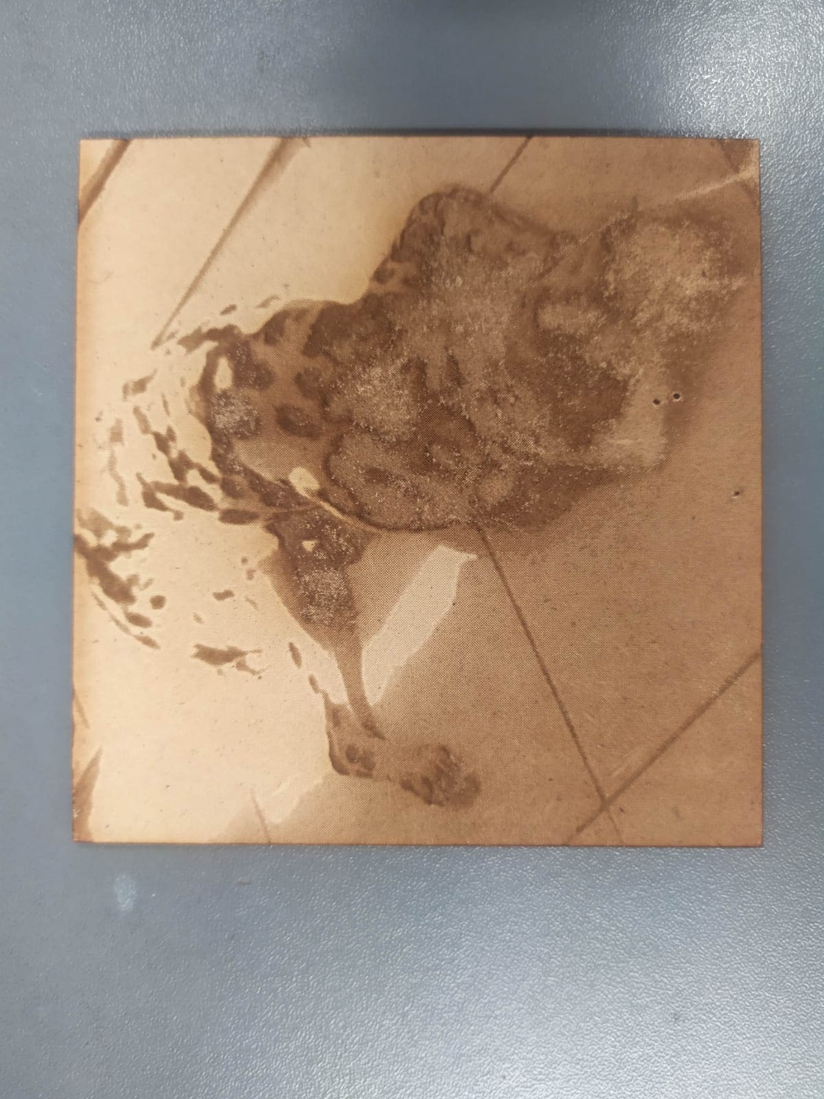
Once familiar with the engraving and cutting process, different materials were tried. The first engraving that I made was on a photo of my dog, before sending the file to engrave, the image was converted to grayscale. In the first attempt, the results were not satisfactory, due to the contrast of the image. Here you can see the original image and the result
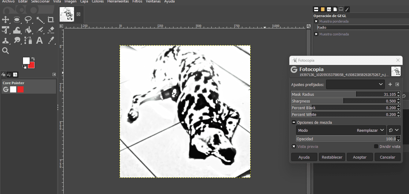
In order to obtain better results, the image was processed in GIMP to obtain a contrast that allows a better final result (filters > artistic > photocopy).
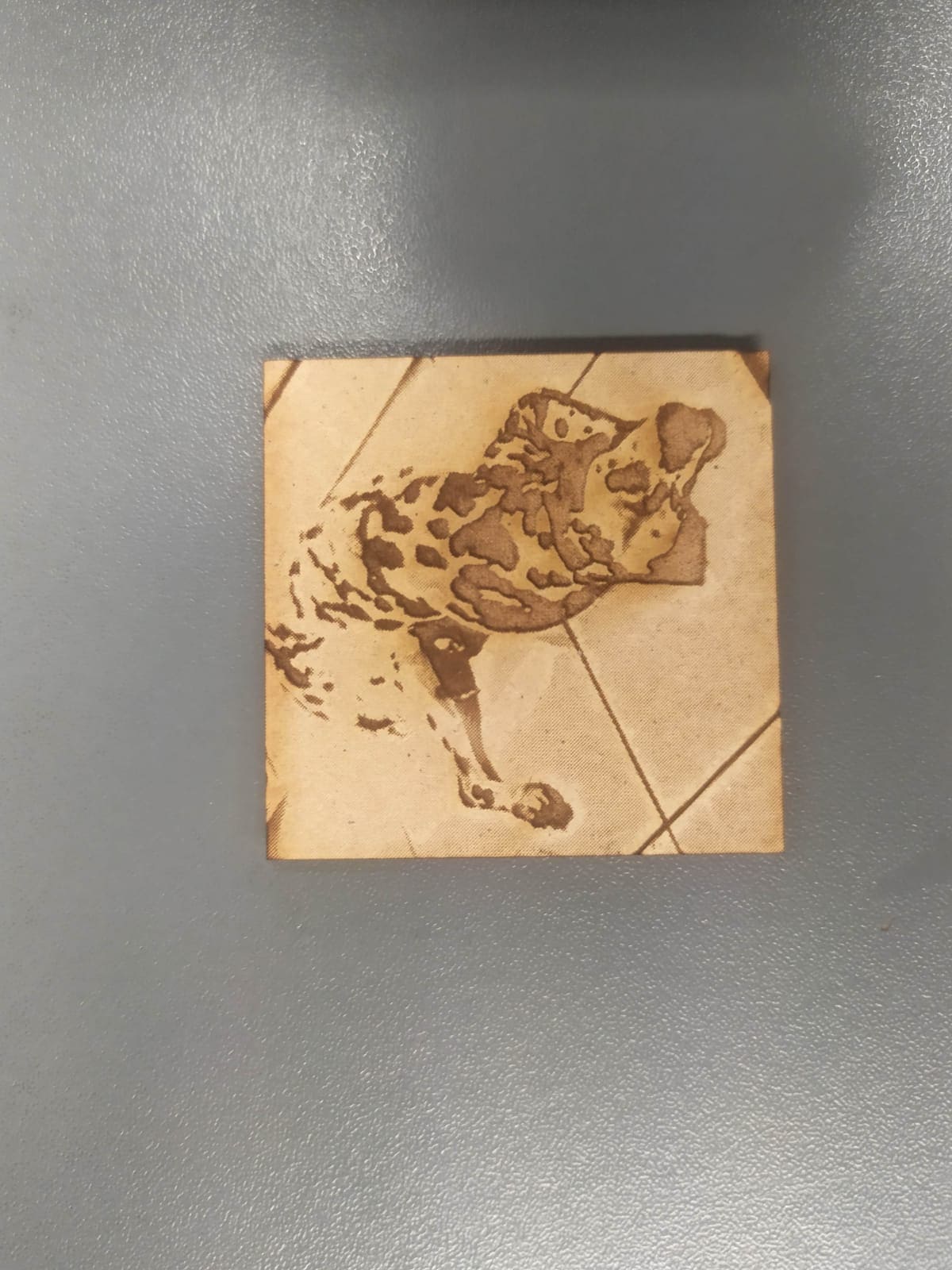
Thanks to this, a better final result was achieved in the materials we tested. Here you can see the cutting process in MDF and acrylic.
And here we can appreciate the final result
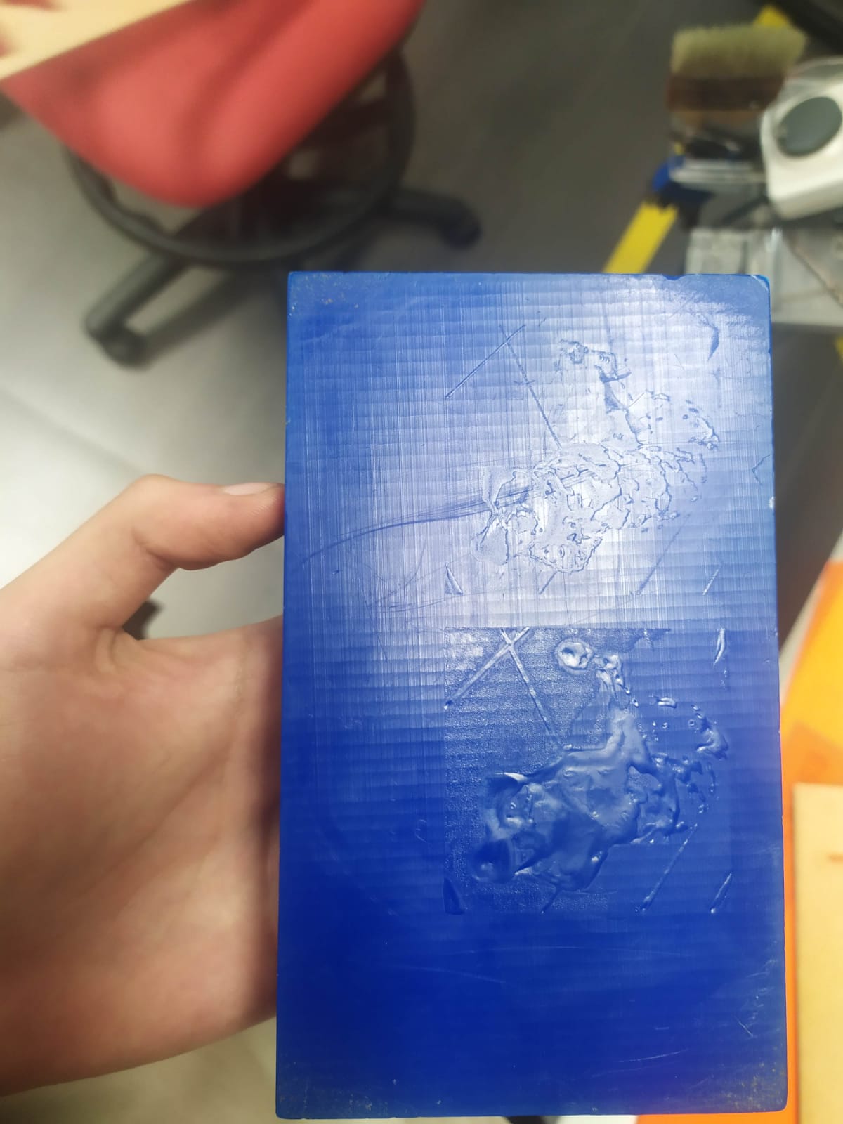
Tests were also made on wax blocks with unsatisfactory results.
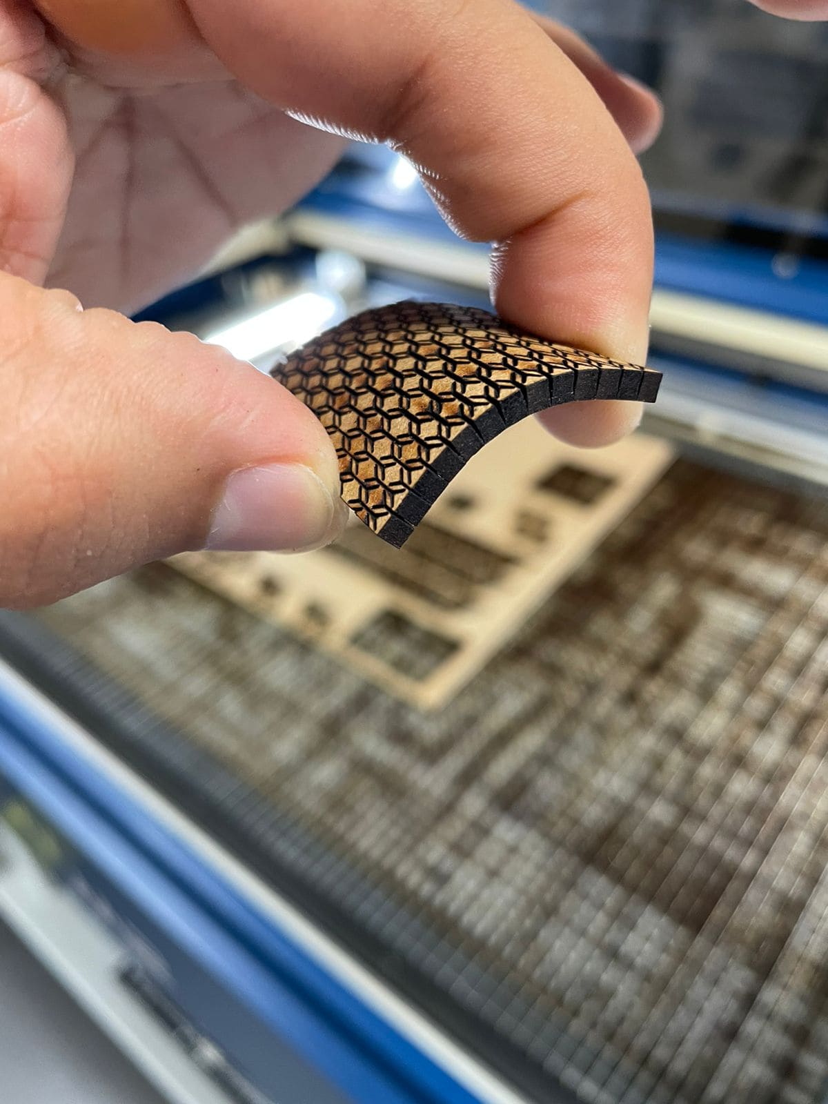
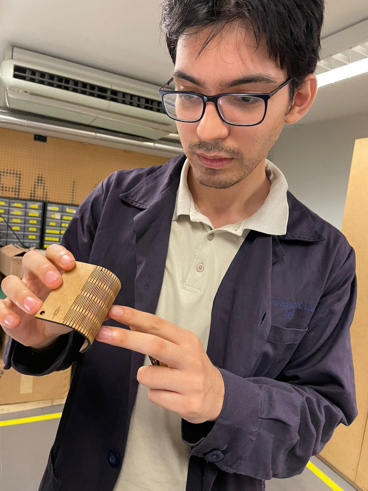
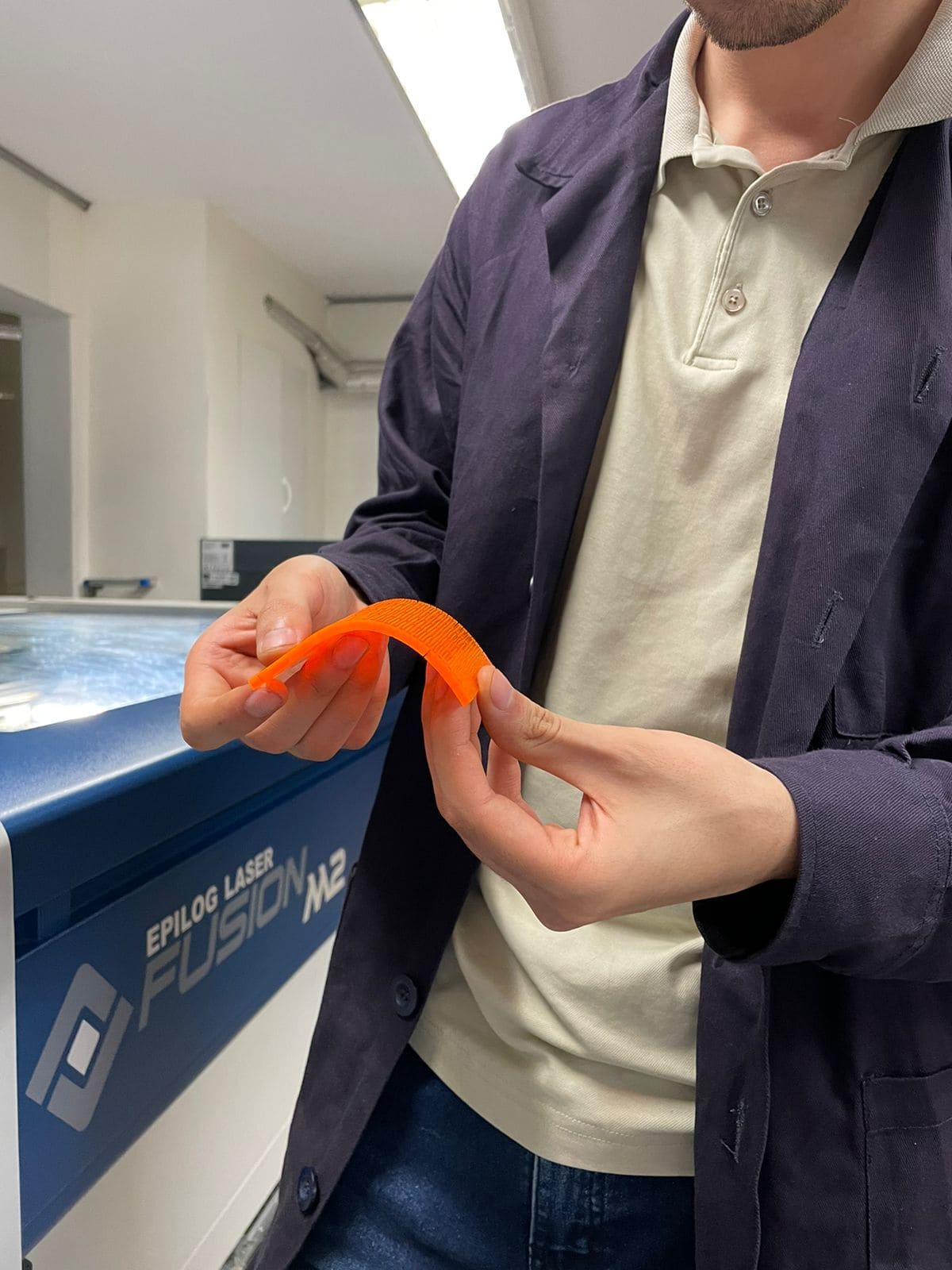
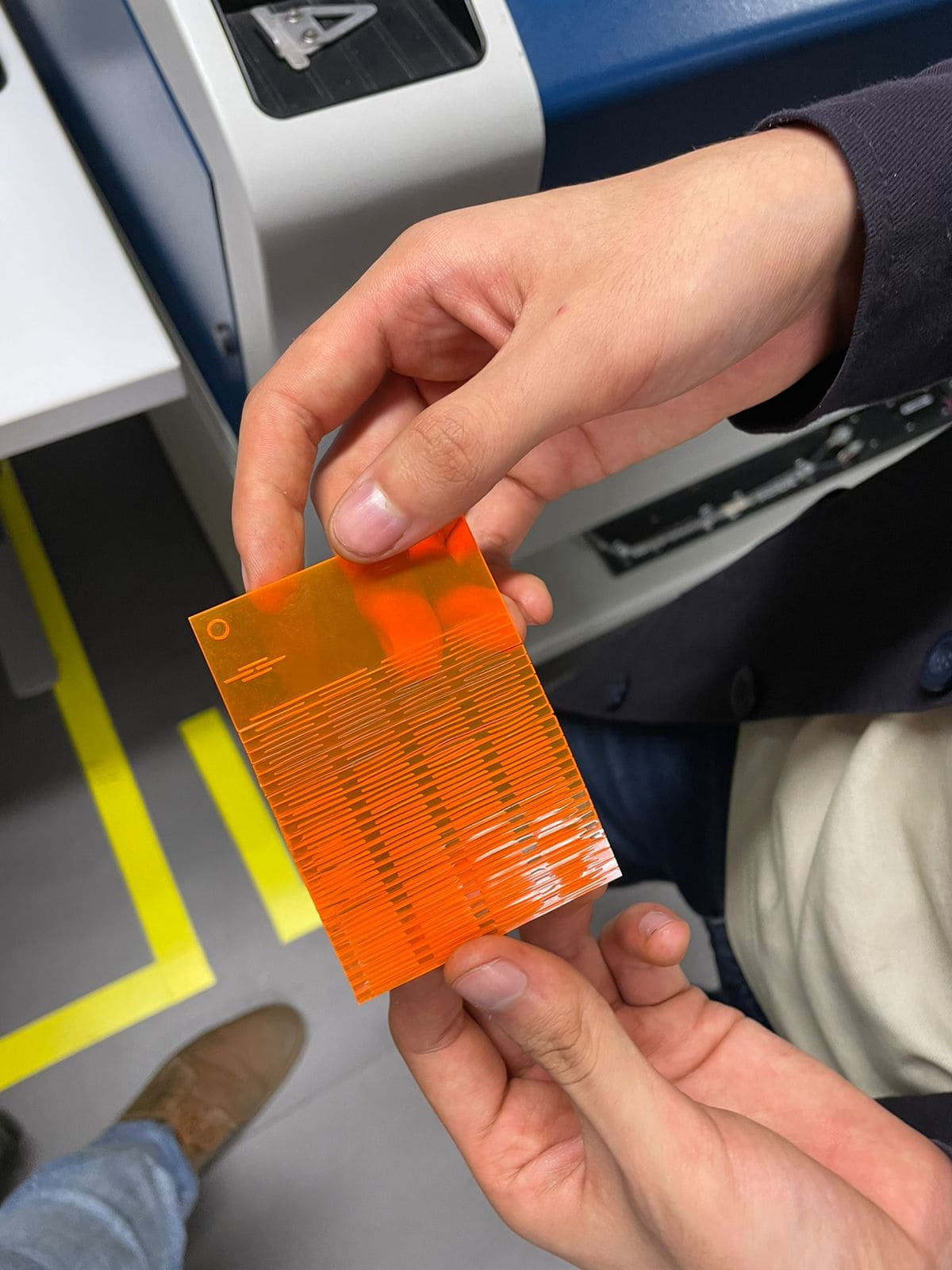
Finally, the cutting patterns were tested to give flexibility to the material:
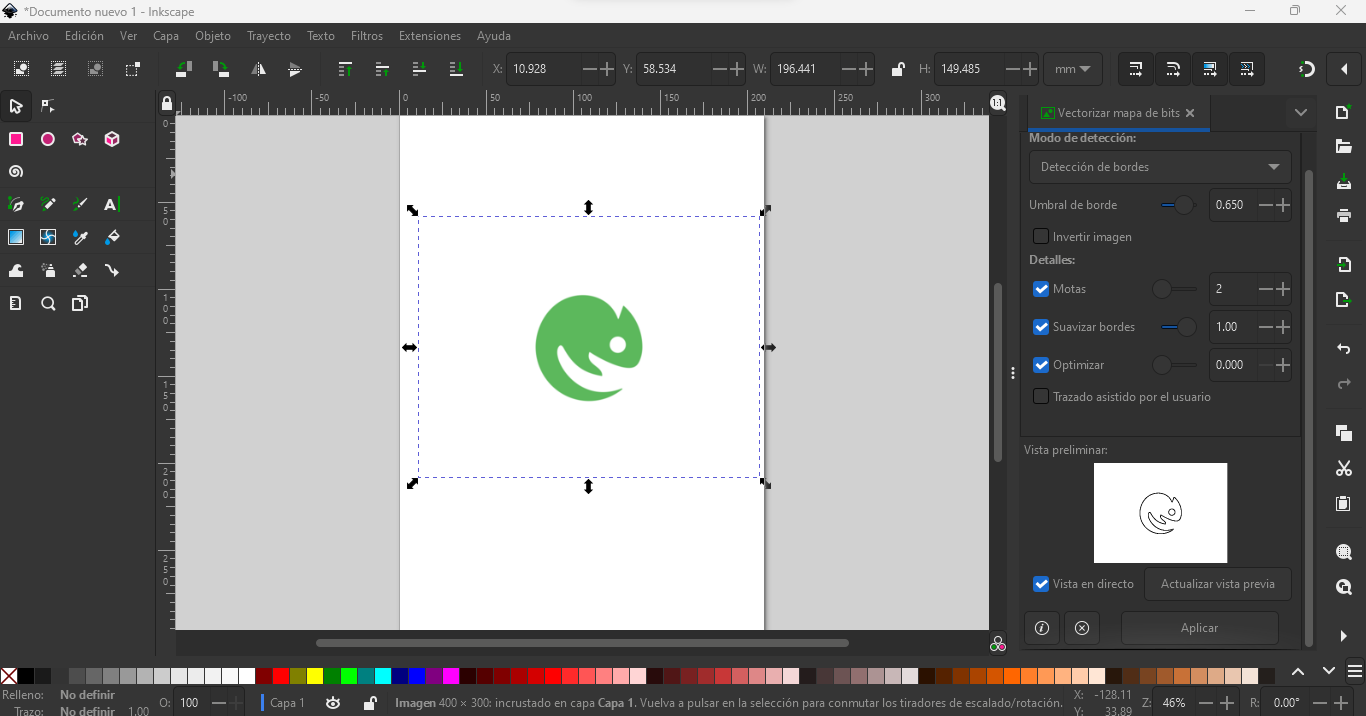
First we import the image in inskape and search for the function vectorize:
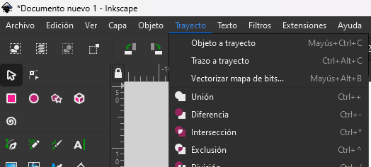
Then we select "edge detection":
Finally we press apply:
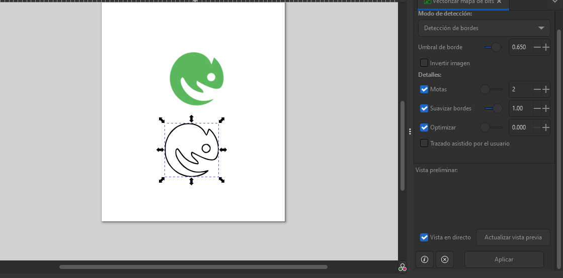
First, I got an image that I liked from the internet and vectorized it using inskape, then inserted it into the Silhouette cameo software where I added the material and cutting parameters such as pressure, steps and speed.
A piece of vinyl is glued onto the plastic template and positioned as shown below.
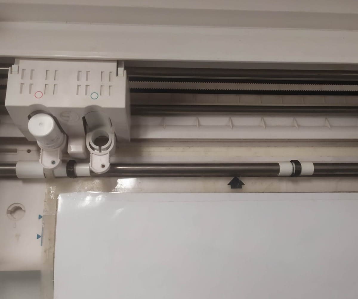
Then load is pressed and we are ready to send the file to be cut.
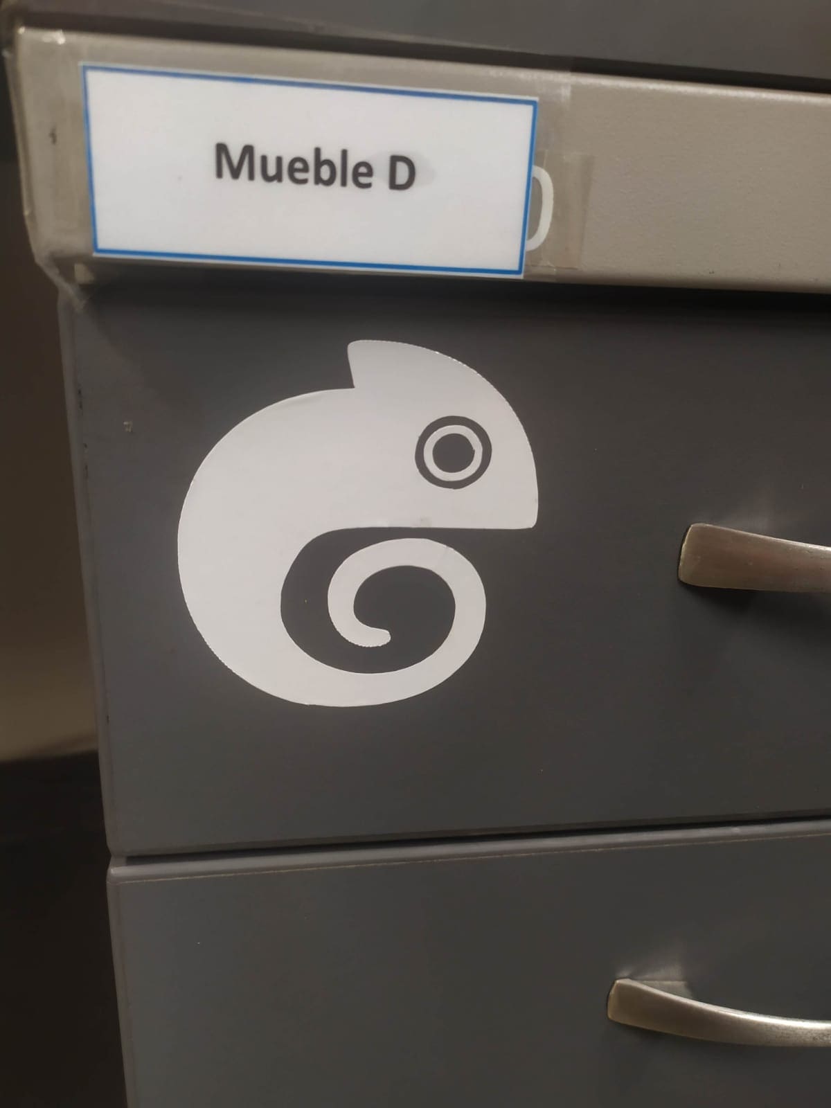
Finally, the vinyl is removed and extracted using a transfer paper and you have it ready to paste it wherever you want.
Here is a tutorial of how to remove the vinyl with transfer paper:
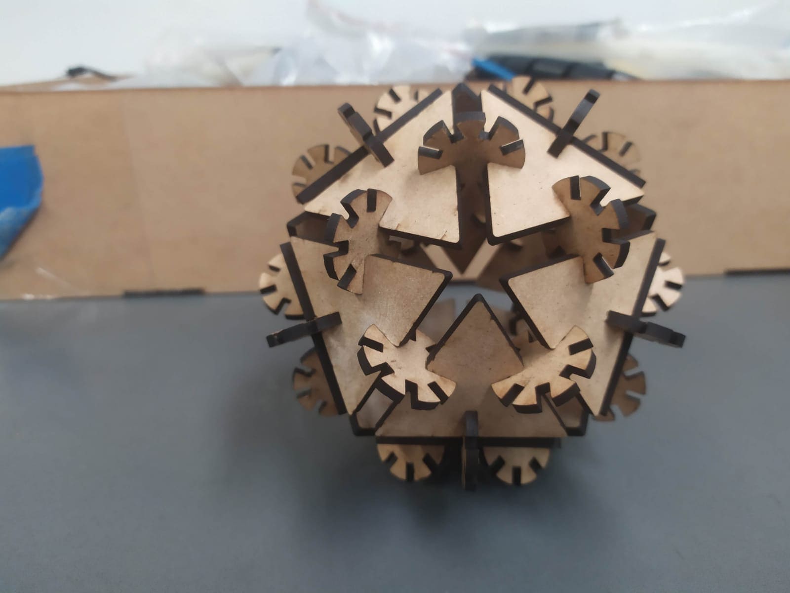
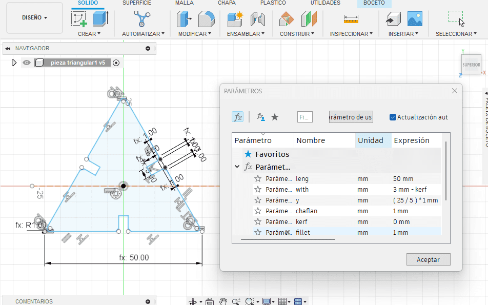
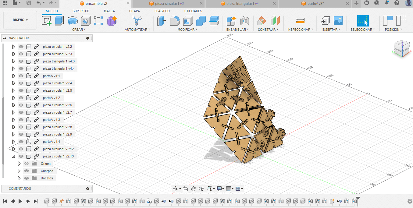
I use Fusion 360 software to do the design using parameters for the dimensions. The design consists of 2 different pieces, where their dimensions vary according to the parameters that one modifies. Here you can see the first piece with its respective parameters.
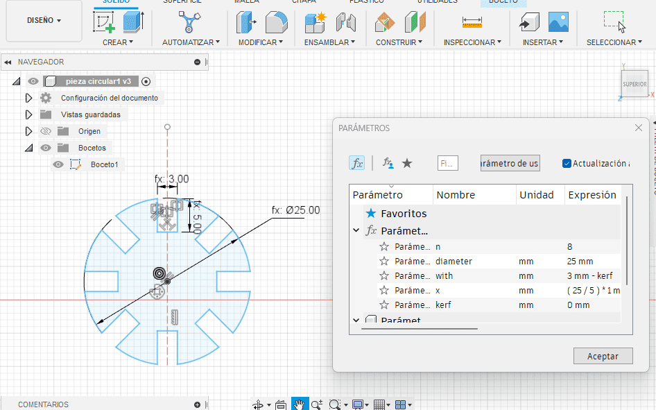
Here you can see the second piece with its respective parameters.
And here you can see one of the possible assemblies that can be done with the kit.
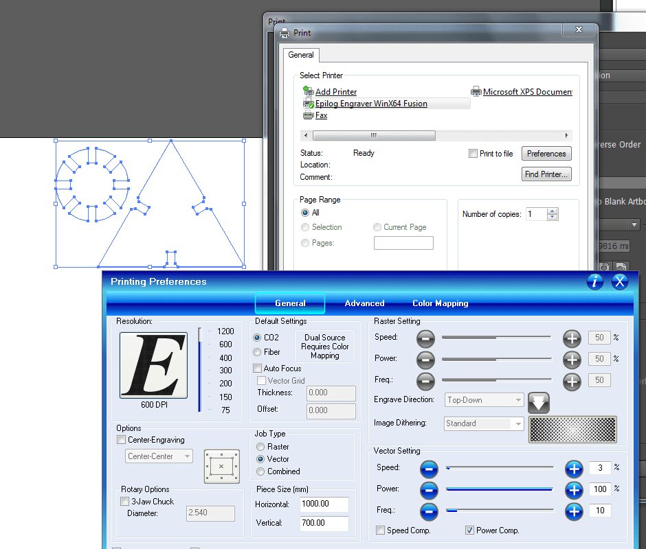
The sketches are exported in dxf format, then we open Adobe Illustrator, which is directly connected to the laser cutter, we place the necessary number of pieces, 23 type 1 and 20 type 2 , we modify the cutting parameters for MDF of 3 mm in vector, 100 power, 10 speed and 10 frequency.
In this video you can see the cutting of the pieces
Here are some figures that can be assembled with the kit.
Stingray
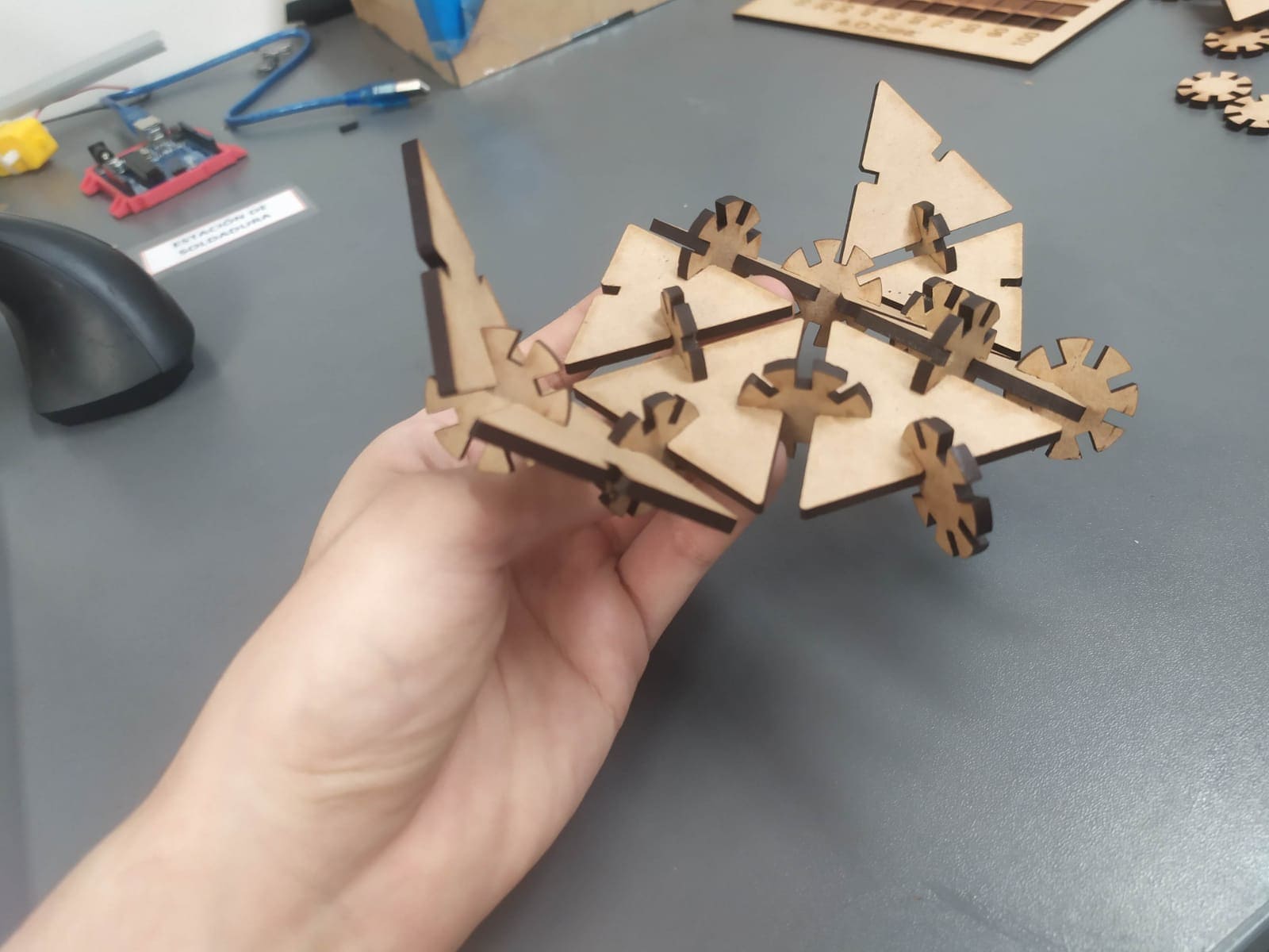
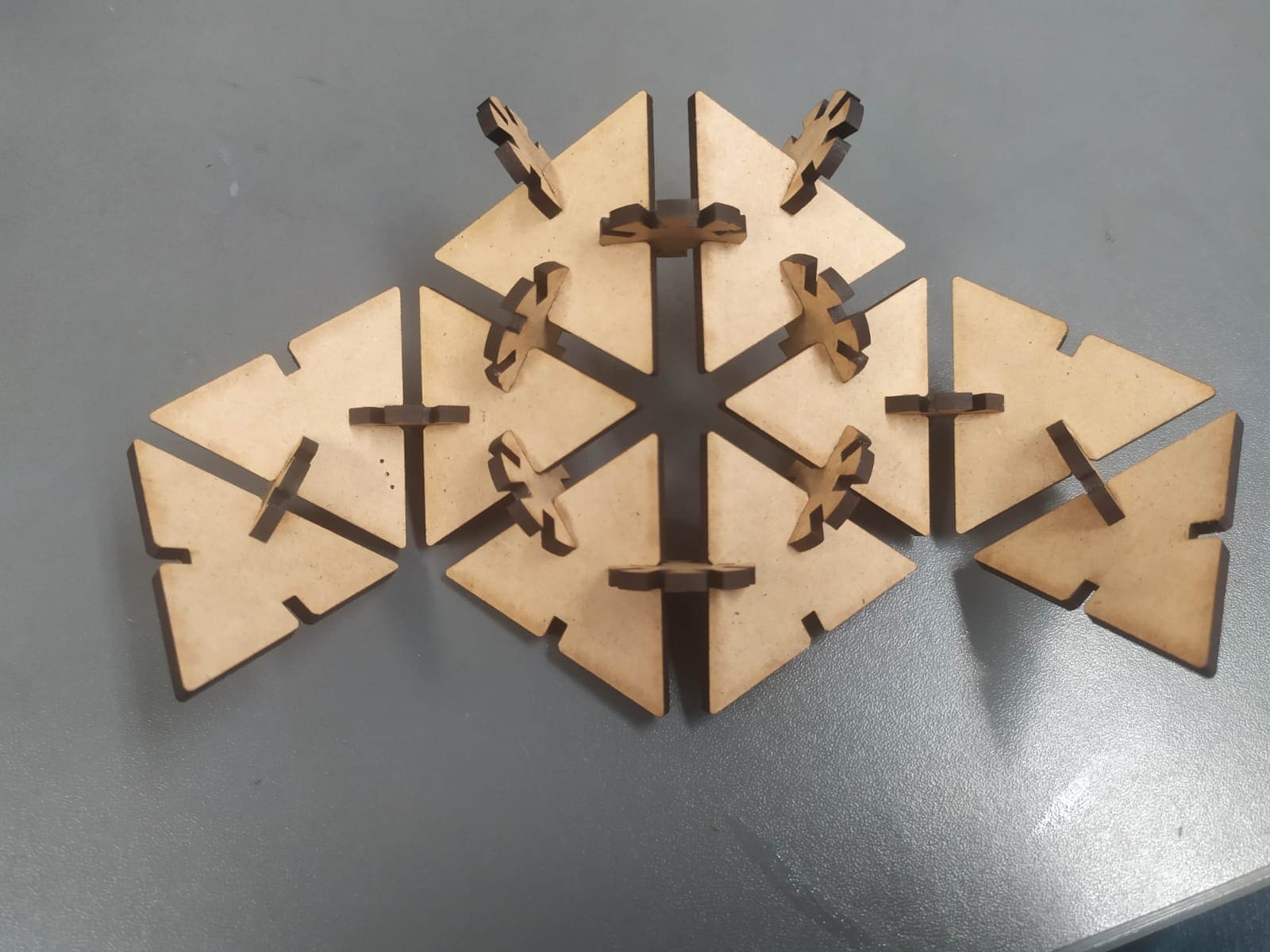
Crab
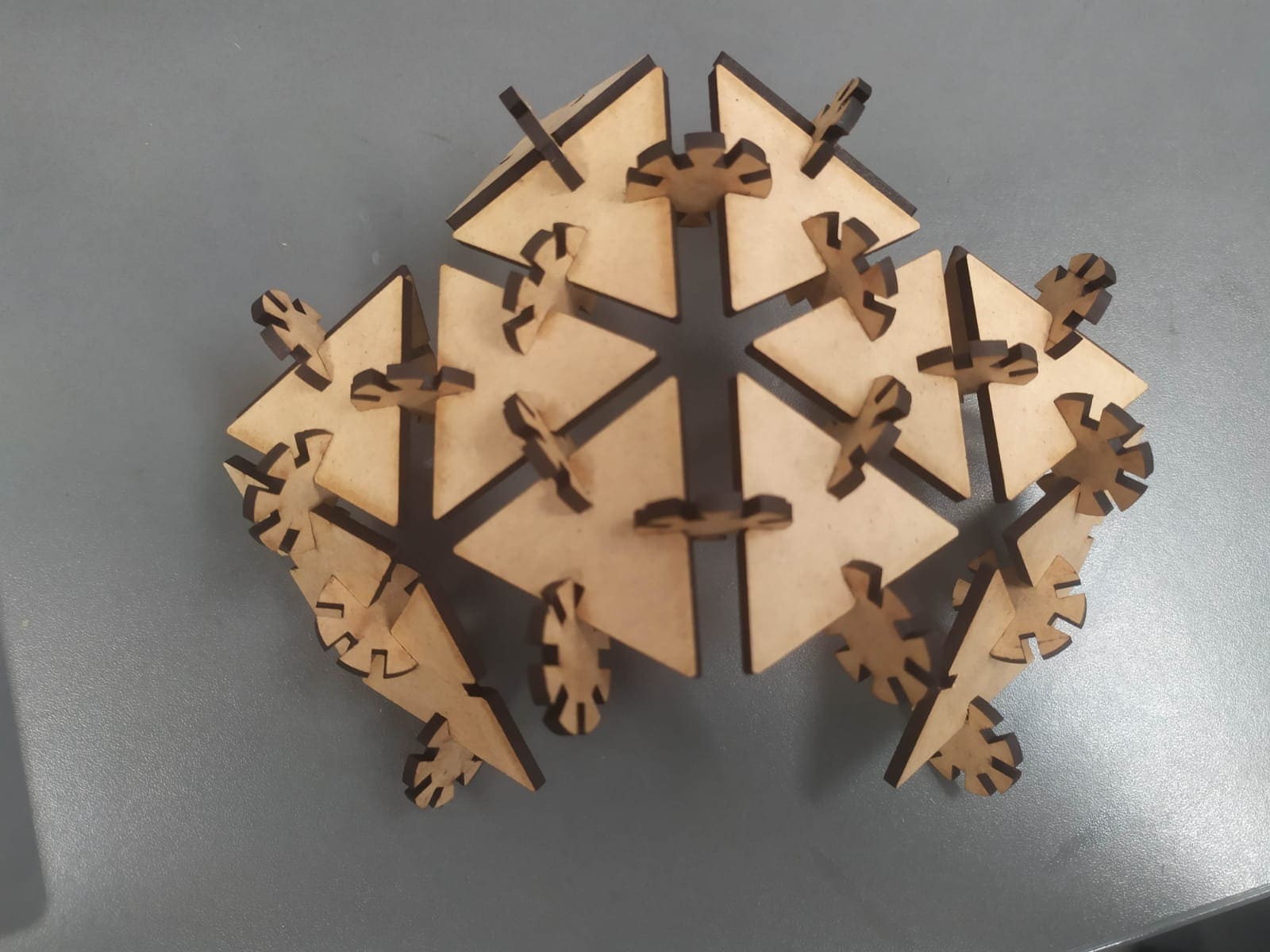
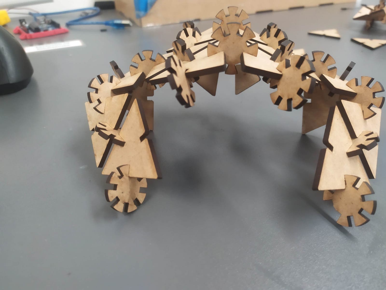
icosahedron