WEEK08. Electronics production
This week I spent time in the physical production of the PCB designed in WEEK 06.
Assignment
- group assignment: characterize the design rules for your in-house PCB production process
- extra credit: send a PCB out to a board house
- individual assignment: make and test the development board that you designed to interact and communicate with an embedded microcontroller
- extra credit: make it with another process.
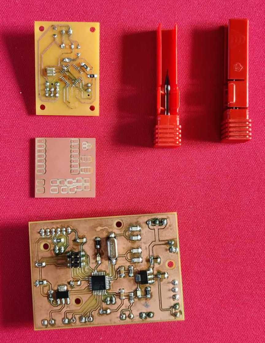
PCB milling process
This week consisted in two main steps cutting the PCB and soldering the components on the PCB. Below are shown some examples of PCB present in the FabLab. Different types of PCB board exist, the commercial ones are the FR4, these are less costly, but cannot be milled with the FabLab machine, because the waste powder is dangerous. So, for safety reasons, in the FabLab we use FR1 and FR2 board that are composed of different composite materials, not dangerous as FR4 ones. The PCB boards have a superficial copper foil. This copper layer is milled to create the electic traces and to isolate the PCB pitches as designed in Kicad. Still for safety reasons, to mill the PCB a mechanical process is implemented rather than chemical one.
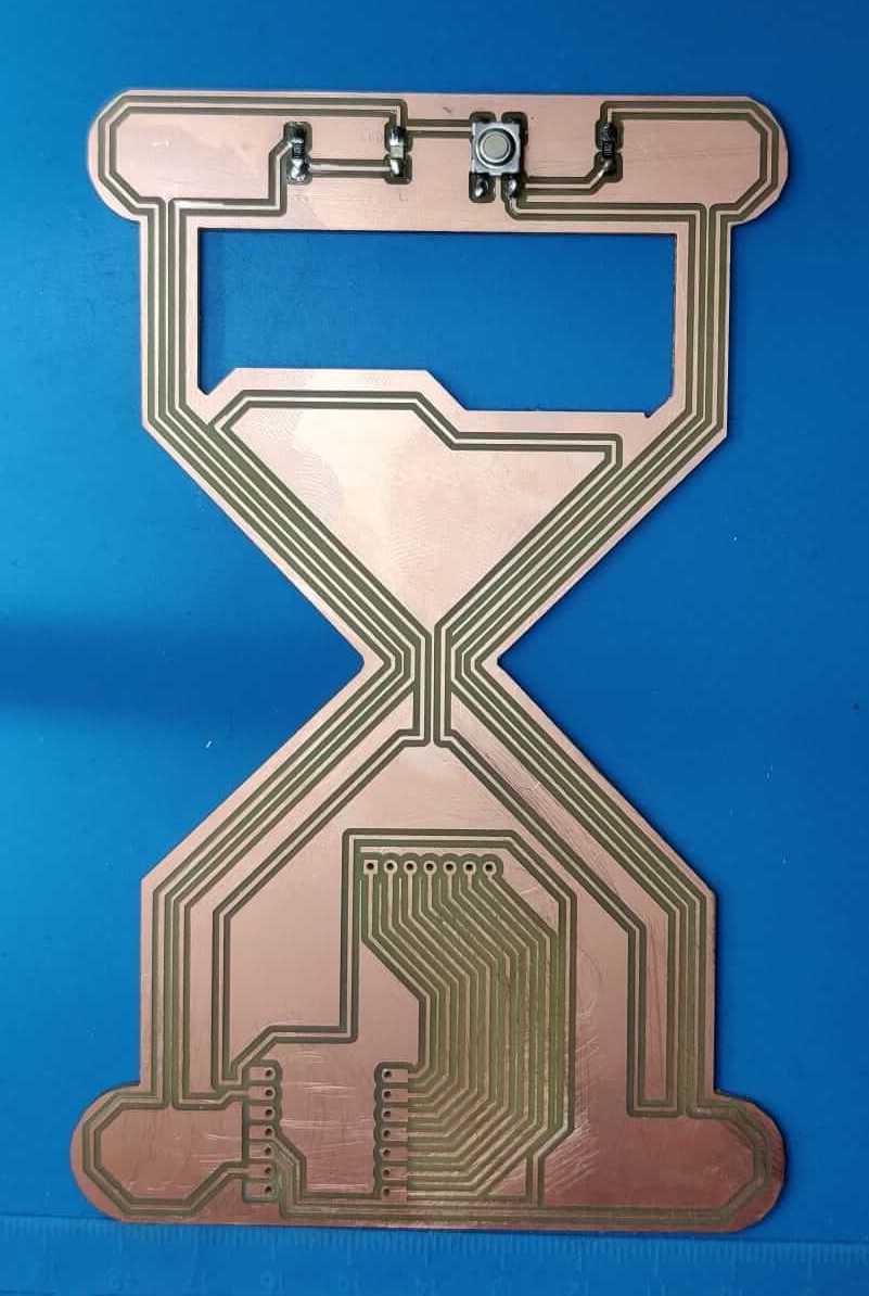
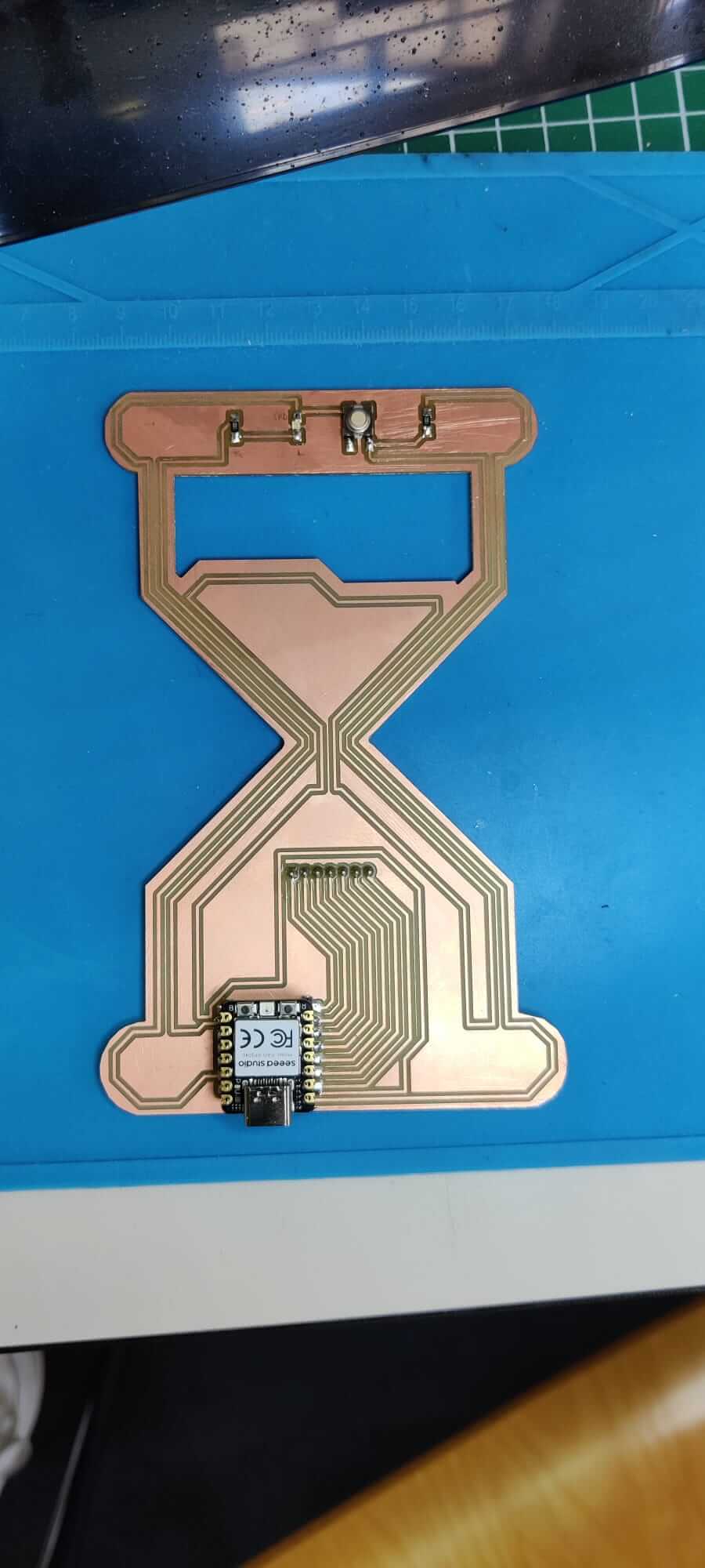
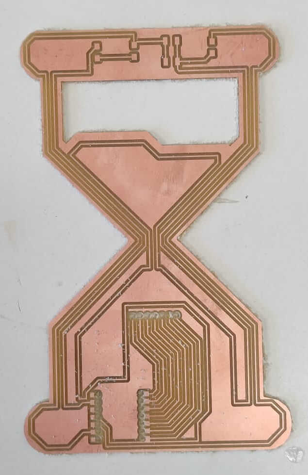
Glass hour PCB Production
Set the technical contraints
In Kicad are setted some constraints in order to project traces that are technically feasible with the FabLab Roland milling machine. Both the minimun diameter for the holes and the minimum distance between traces are setted, according to the mill bits used. Moreover it is important to consider that with Roland milling machine it is possible to mill the PCB only on the front surface (for this reason the traces in Kicad are drawn only on the F.Cu layer).
Kicad PCB editor: errors checking and export
In the Kicad PCB editor I runned the error checking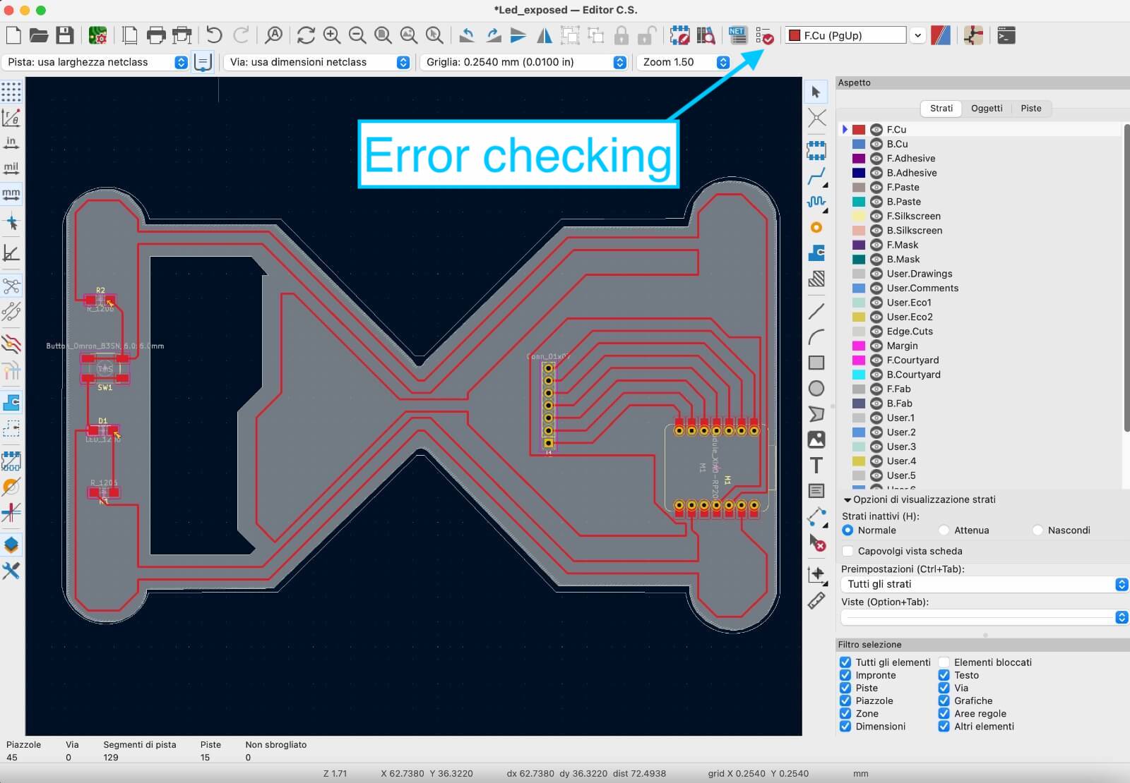
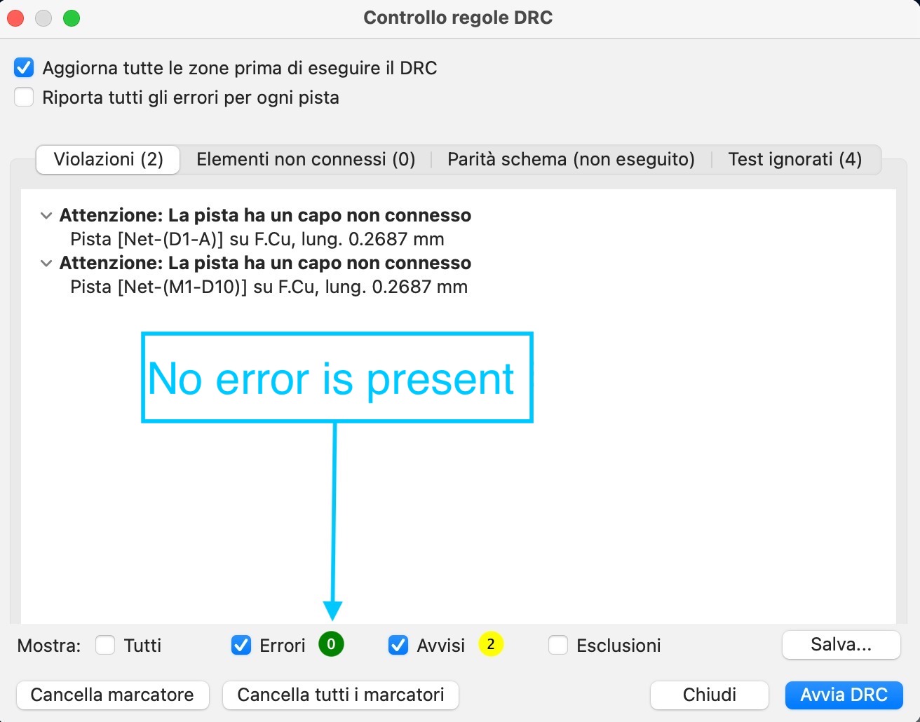
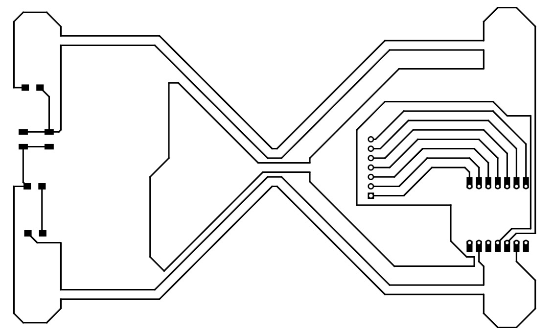
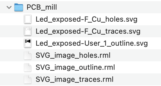
I checked that no error is present, then I exported the .svg file, I created a file for each layer, because the different layers must be cutted using two different mill bits. So, in the PCB editor of Kicad I used the different layers as follow:
- F.Cu: to draw the PCB traces
- Edge cuts: to draw the board size, that it is useful in the export phase
- User.1: to draw the outline


FabModule for the Roland milling machine
To communicate with this offline machine a FabModule was created in the previous years. With this module you can import your .svg files and transform it in .gcode files for the Roland milling machine, with the extension .rml. The path to reach the Roland open program in the FabModules is: modsproject.org > programs > open program > machines > Roland > SRM – 20 > PCB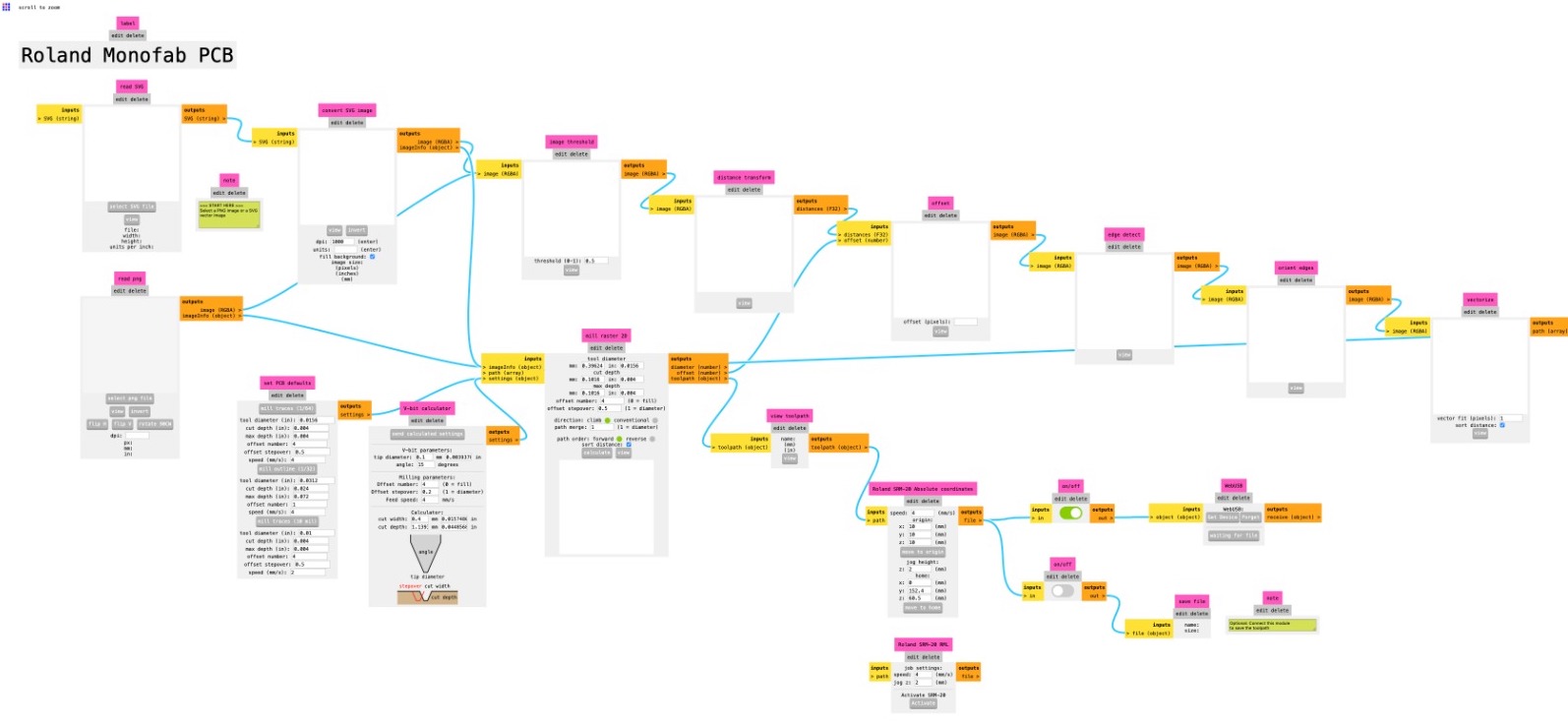
In the FabModule program interface you can import the .svg file.
In "origin" menù set the coordinates of x, y, and z equal to zero.
Since the machine cut only on black zones, in "Convert svg image" menù click on invert button to calculate the right path of the milling machine.
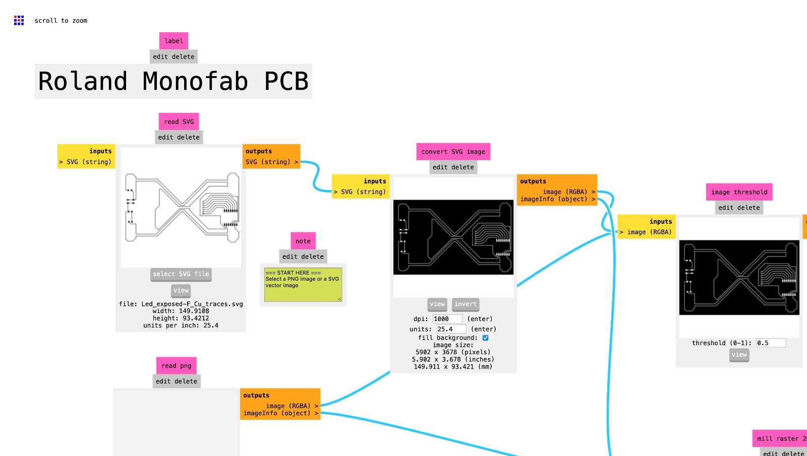
The program is built to set the different machine parameters, starting from the milling bits that you plan to use for the specific .svg file that you are working on. Select the mill bits that you are going to use to cut the file you are working on.
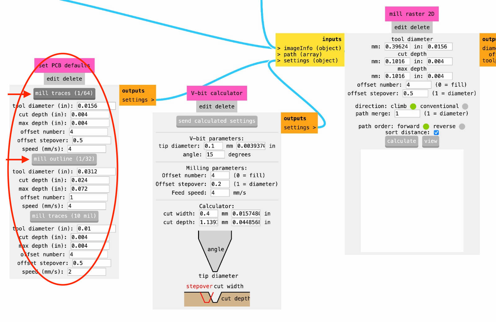
When all the parameters are correctly setted you can proceed clicking the "calculate" button to create the .gcode file in the Roland language, then click on "view" button to explorate the file. Finally, if the result is satisfying you can save the file.
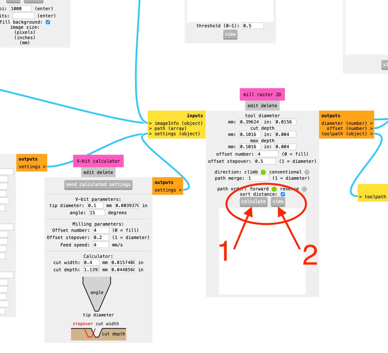
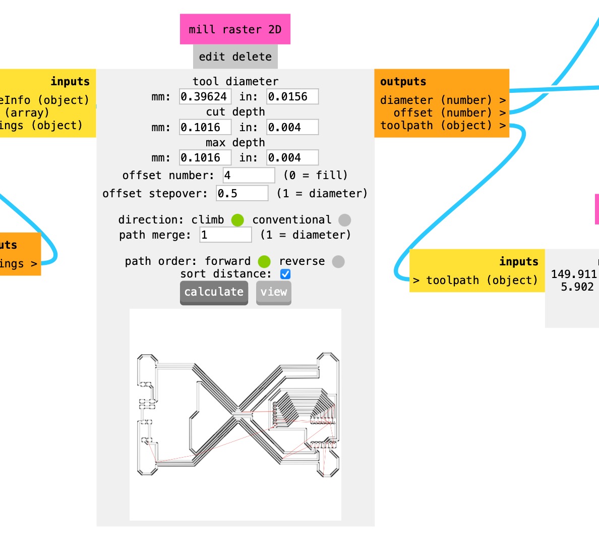
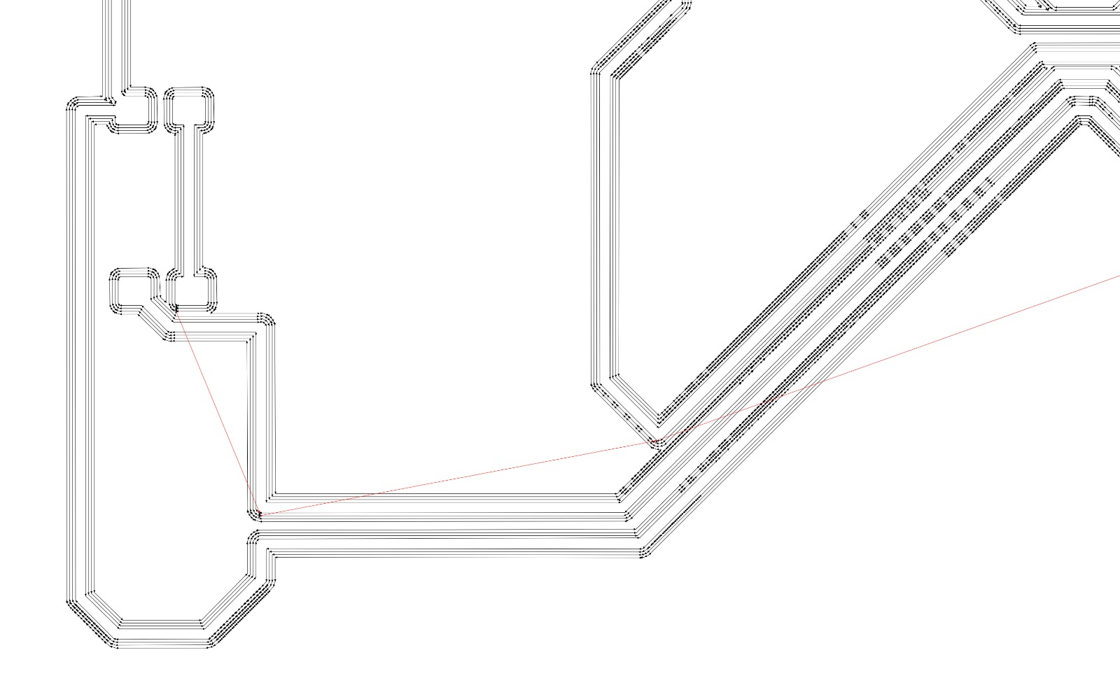
Remember always to check the path of the milling bits before saving the file.
According to your needs, you can turn on or off the saving options. The file are finally saved in a local folder.
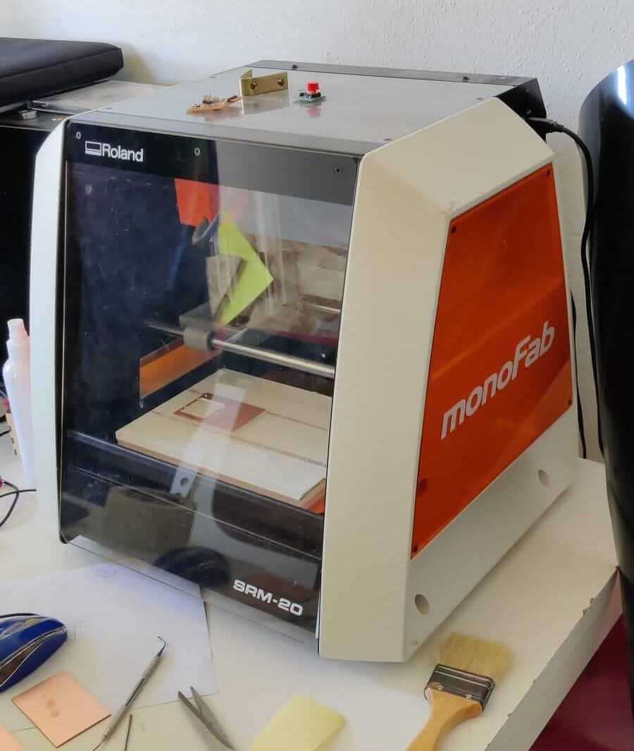
PCB Roland milling machine
To cut the traces, the holes and the outlines of the PCB the Roland milling machine is used. Roland monoFab SRM-20.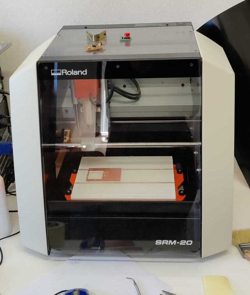
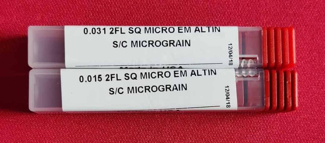
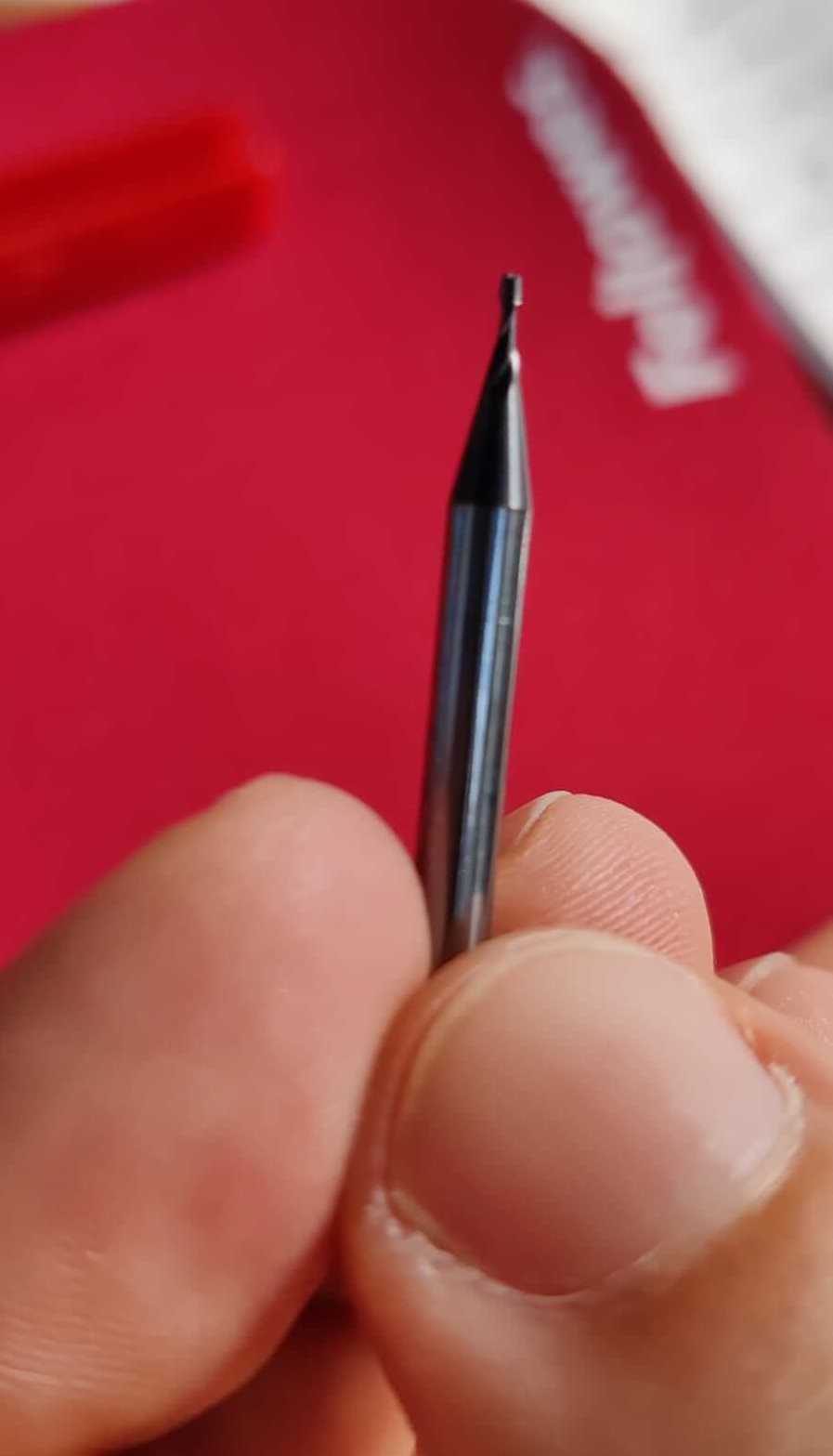
 To create the PCB are used two different types of mill bits, in order to remove a known quantity of material at each stage.
The dimensions of the mill bits are expressed with the imperial measures, especially in the FabLab are used:
To create the PCB are used two different types of mill bits, in order to remove a known quantity of material at each stage.
The dimensions of the mill bits are expressed with the imperial measures, especially in the FabLab are used:
- Mill bits of 1/64 inch - 0.015: to mill the traces and the pitches.
- Mill bits of 1/32 inch - 0.031: to mill the holes and the outlines.
 The milling machine does not change autonomously the mill bits so it is necessary to save different .rml files and run them one at time.
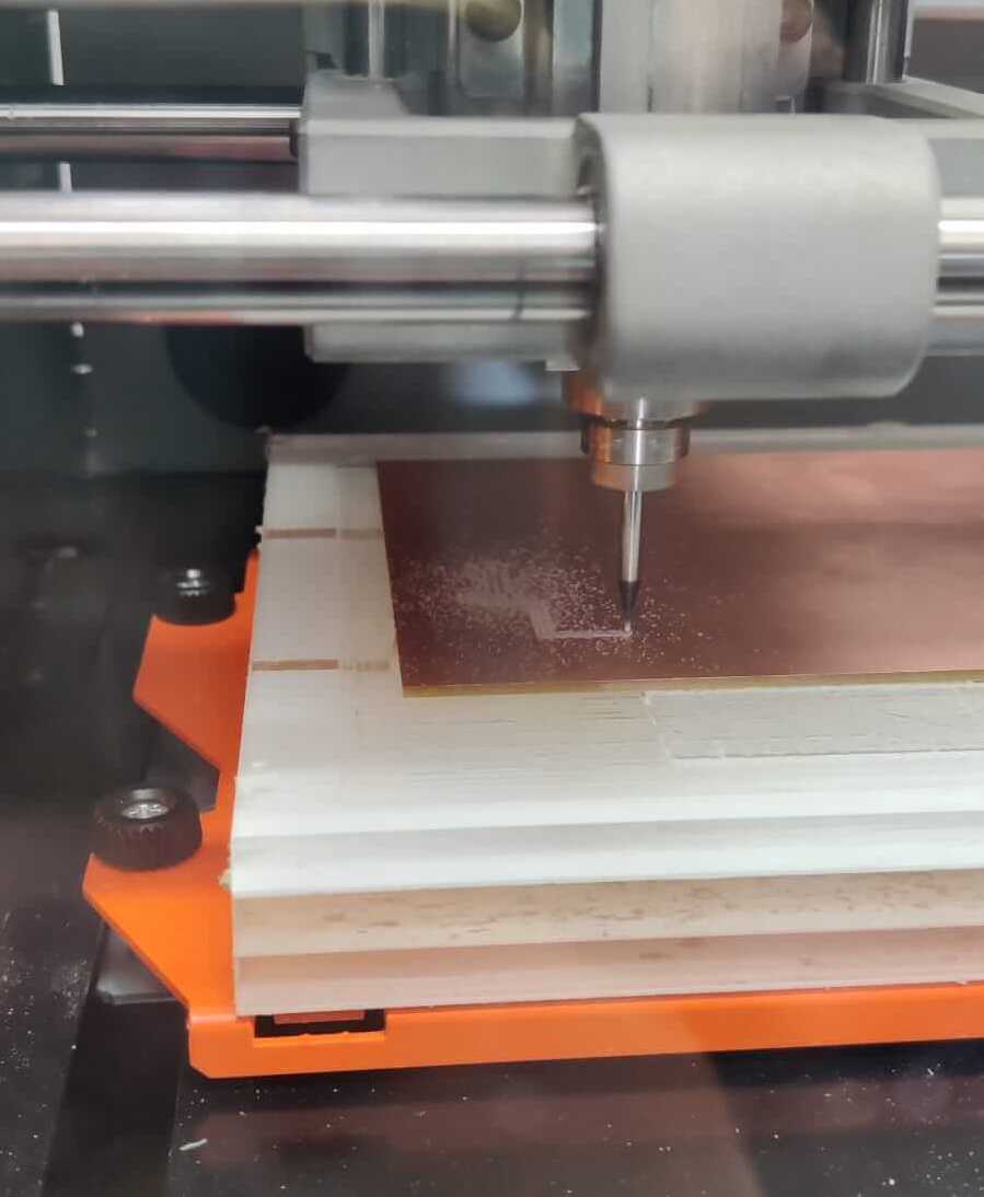
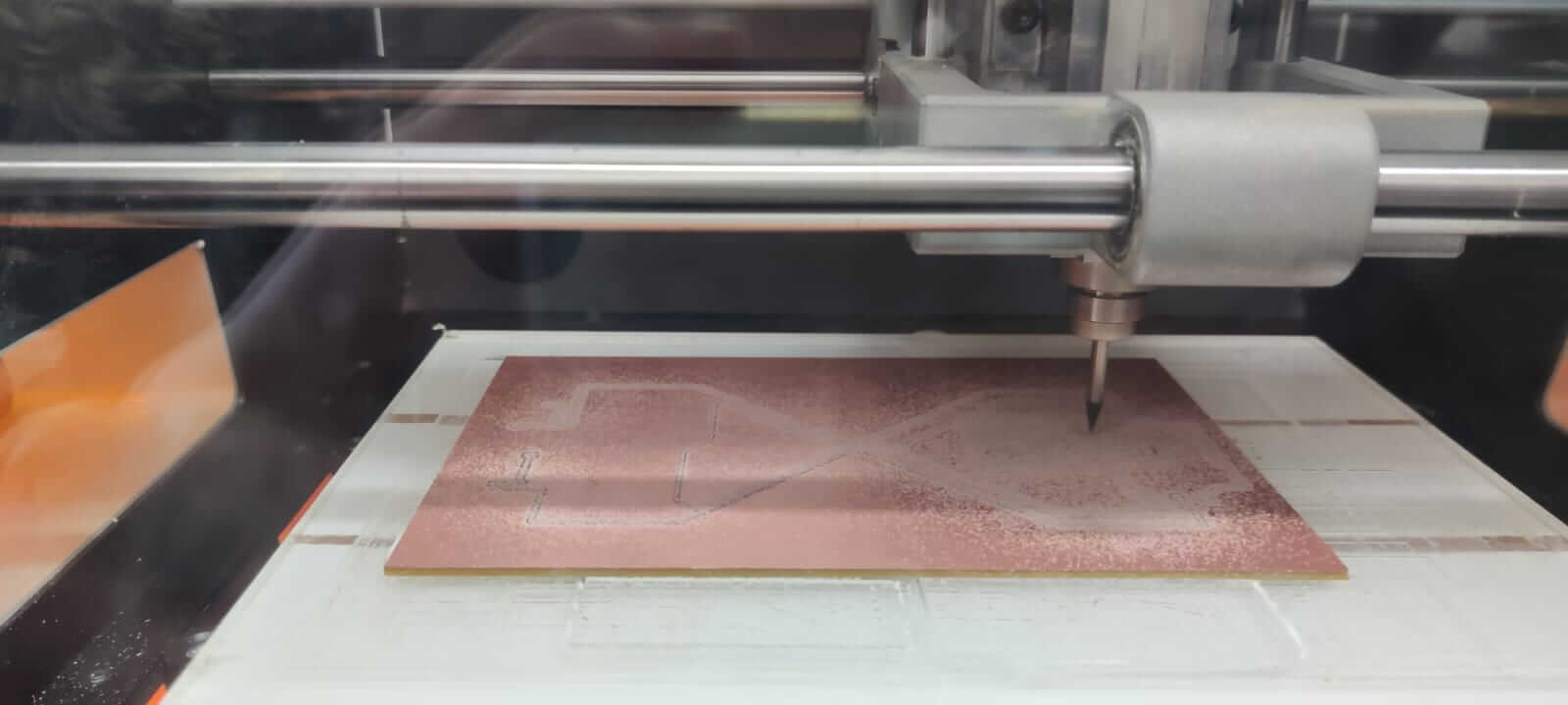
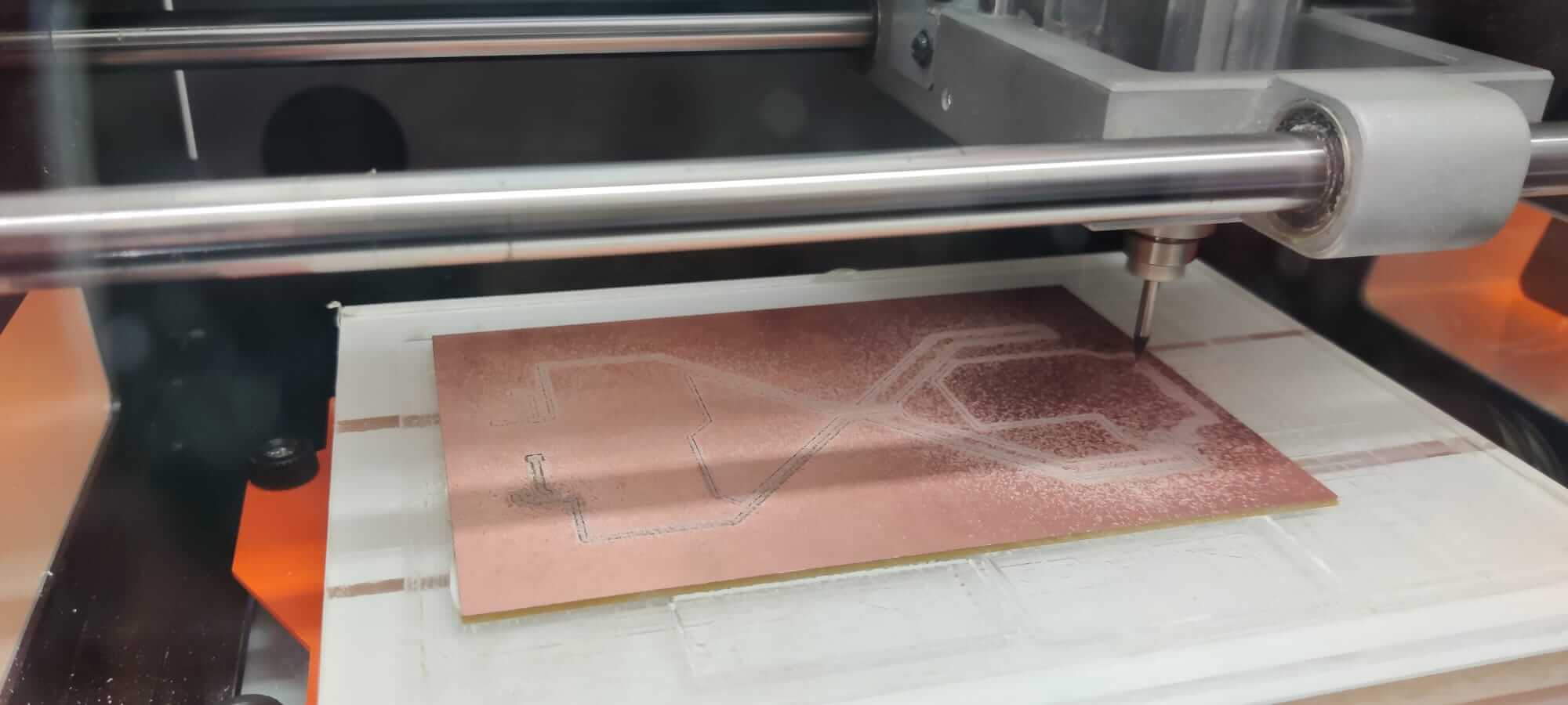
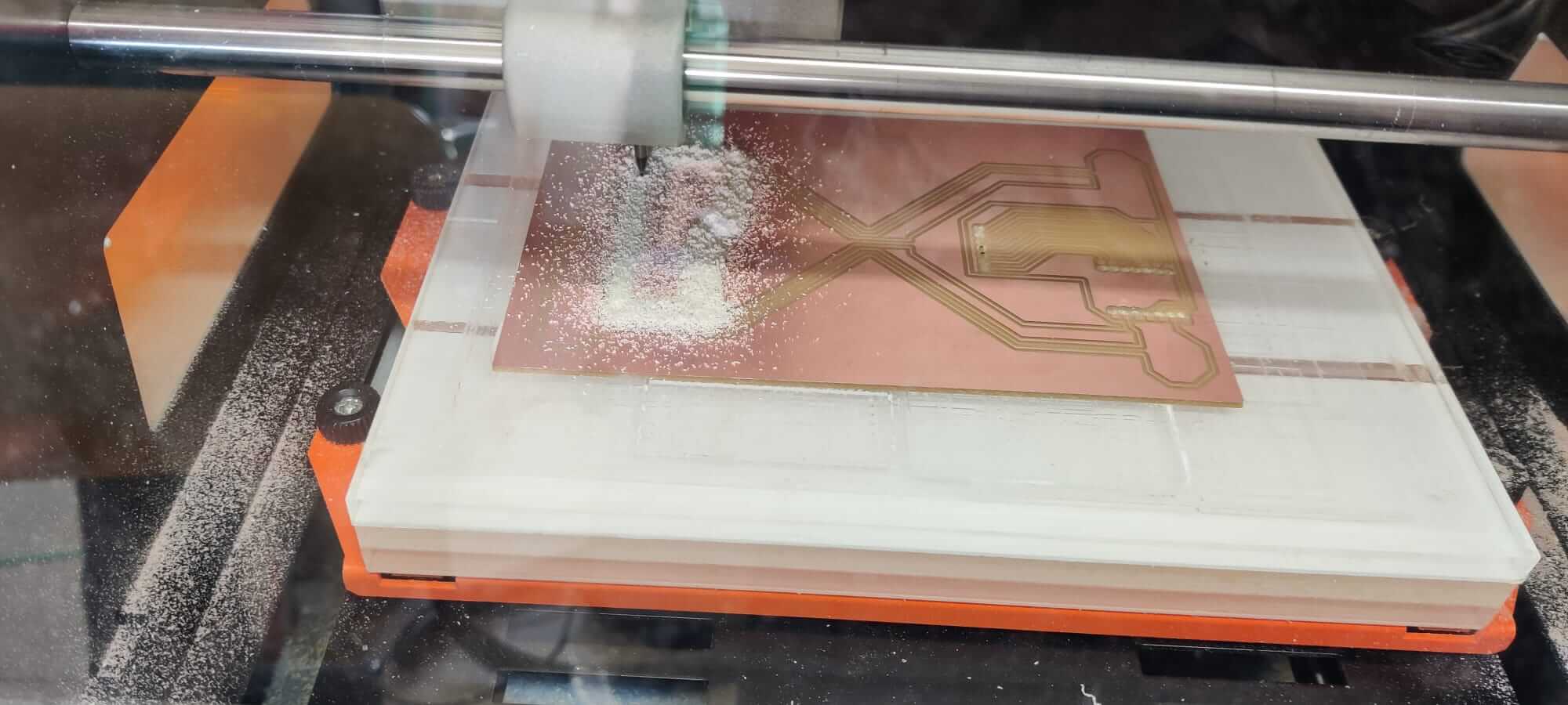
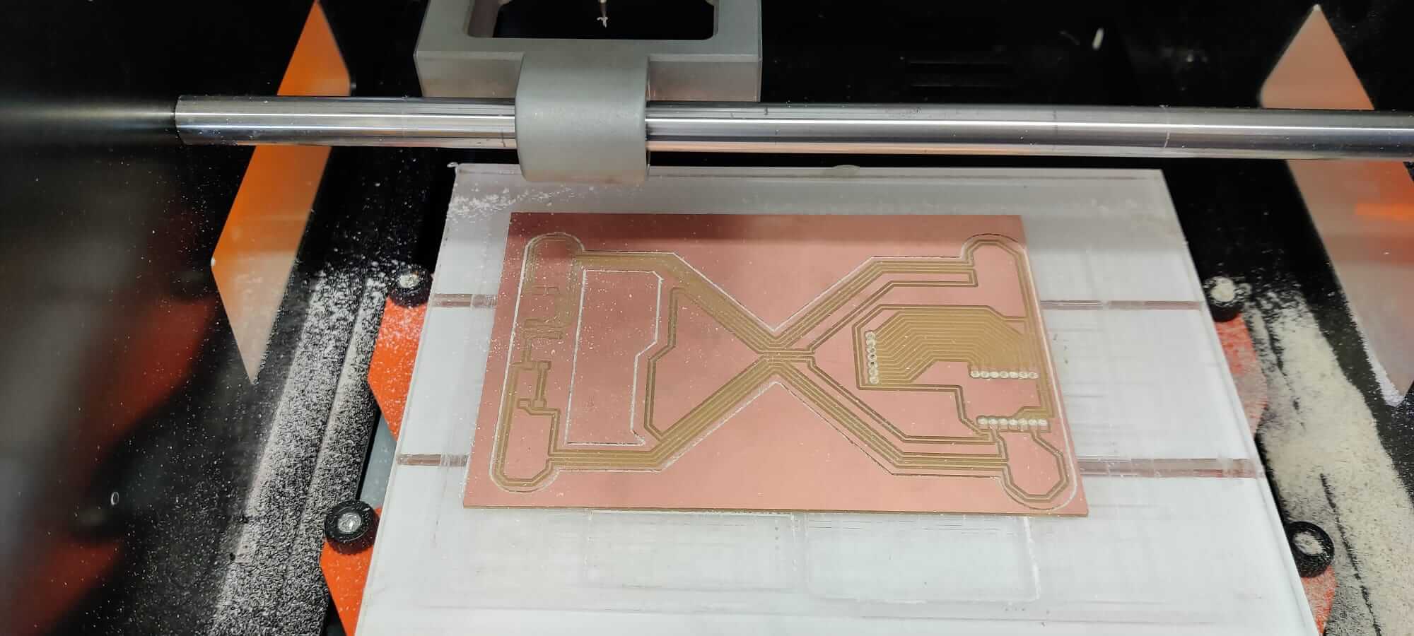
Milling process
The first file to be runned is the one with traces, then the holes, and finally the outline. The FR2 board is fixed to the plexiglass X/Y plate using the double sided tape.Set origin position
The machine is setted using the computer interface.- Set the X/Y origin
- Set manually the Z axis
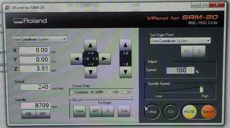 The origin X/Y must be the same during the whole process, instead a new Z is required after each change of milling bits.
After the new Z aquisition and before starting to run a new .rml file remember to put the mill bit in the X/Y origin position previously setted.
Press on "cut" button and in the new window add the .rml file that you want to run. Finally click on "output" button to start the milling machine.
The origin X/Y must be the same during the whole process, instead a new Z is required after each change of milling bits.
After the new Z aquisition and before starting to run a new .rml file remember to put the mill bit in the X/Y origin position previously setted.
Press on "cut" button and in the new window add the .rml file that you want to run. Finally click on "output" button to start the milling machine.
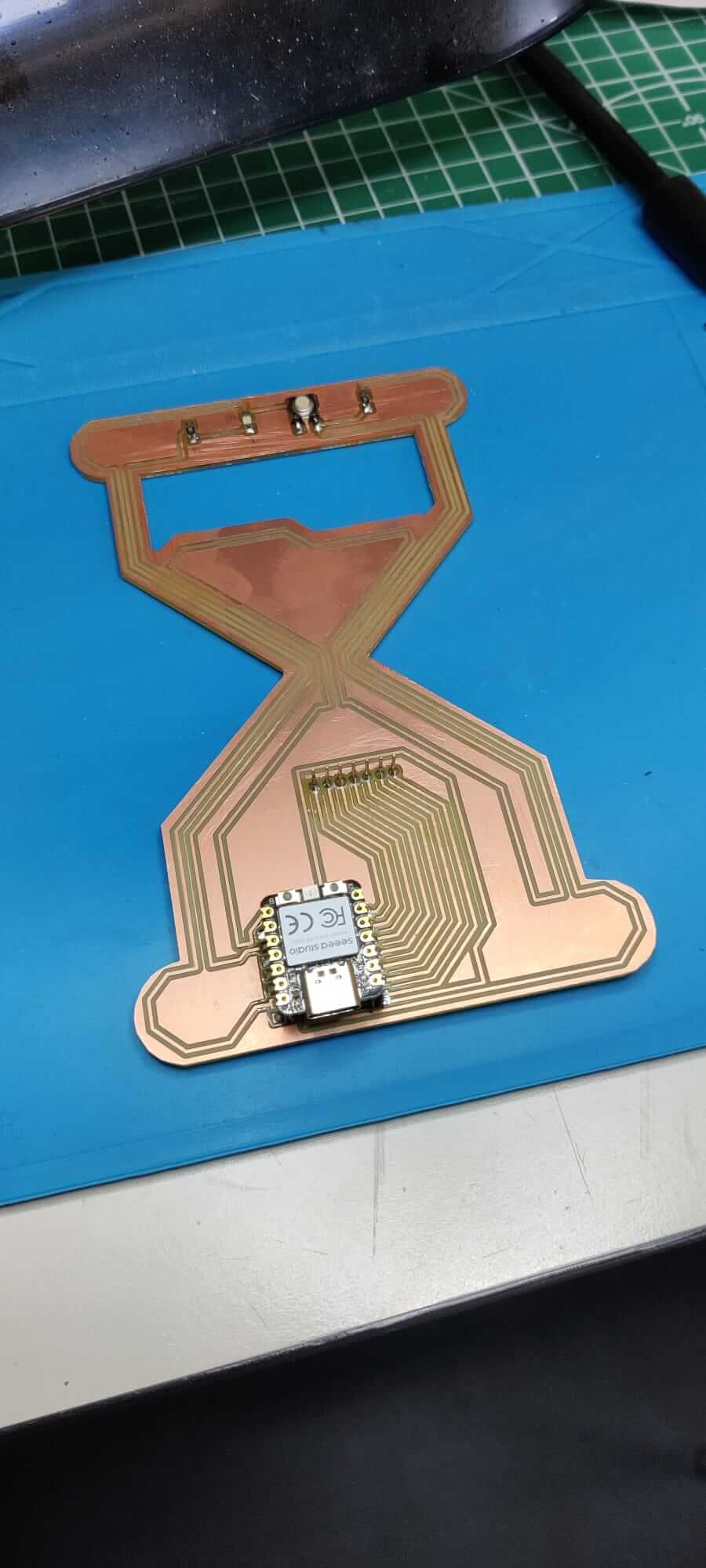
Soldering process
When the PCB milling is finished, you have to solder the components on the PCB board, coerently with the board drawn on the Kicad editor. The components needed are selected from the components warehouse.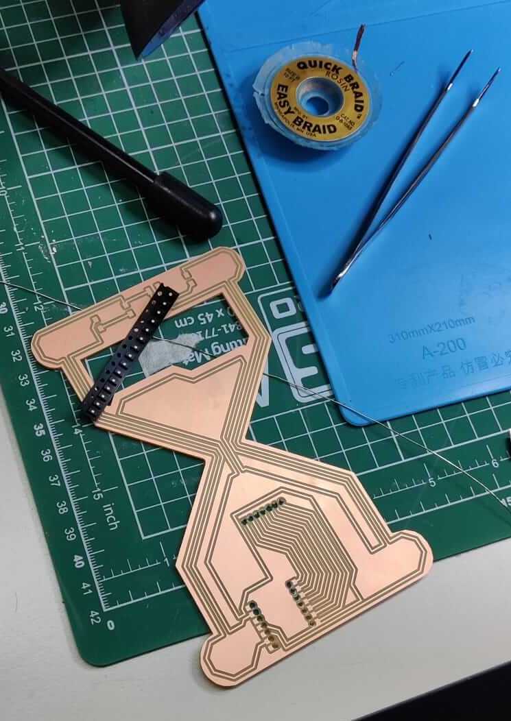
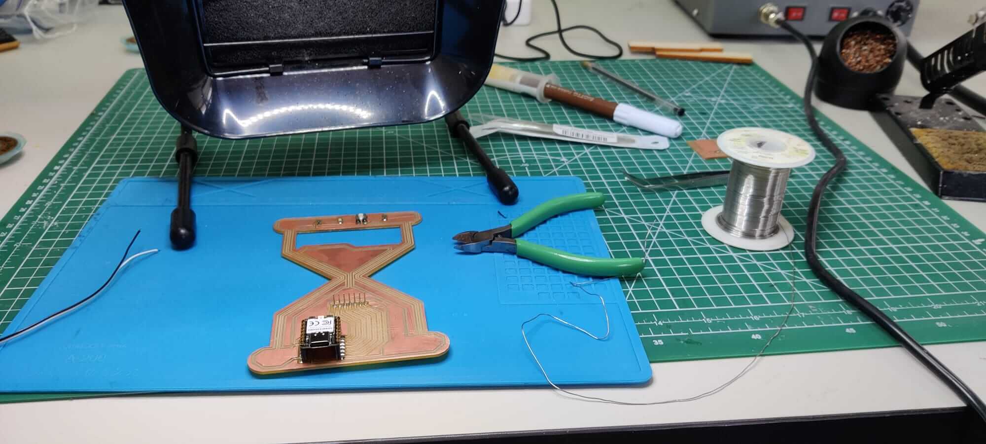
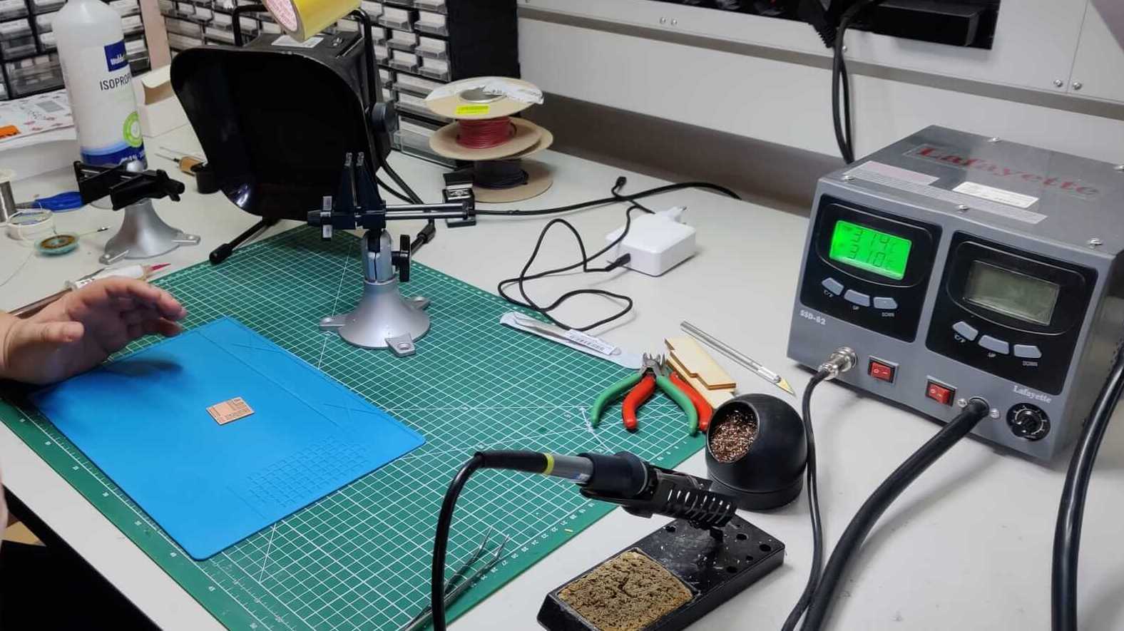
Since the components are really small, it is crucial to prepare a good working station. A silicone pad is suggested to increase the attrition with the board an to help to maintain in position the PCB during the soldering process.
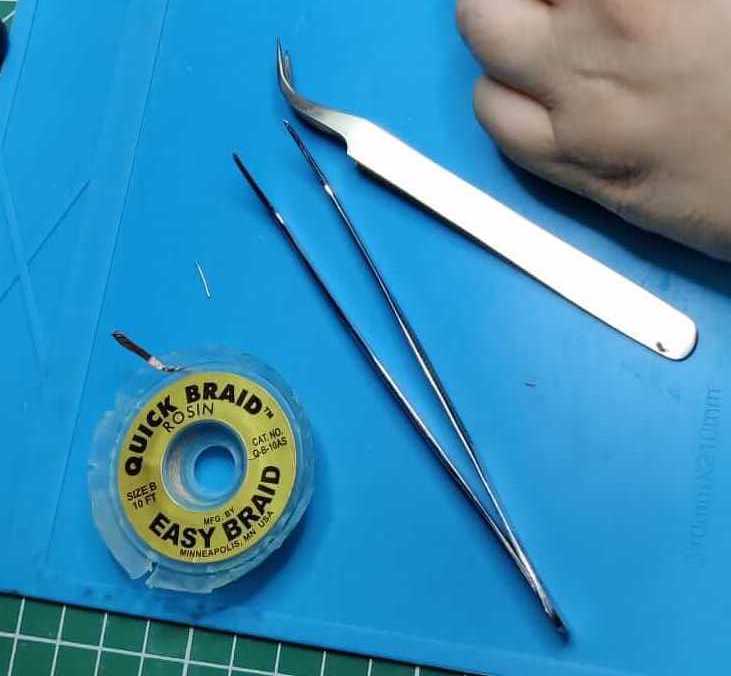
Moreover, a pair of needle nose pliers are used to grab the small components.
The copper braid might be useful in case you need to remove the exess of copper on the board.
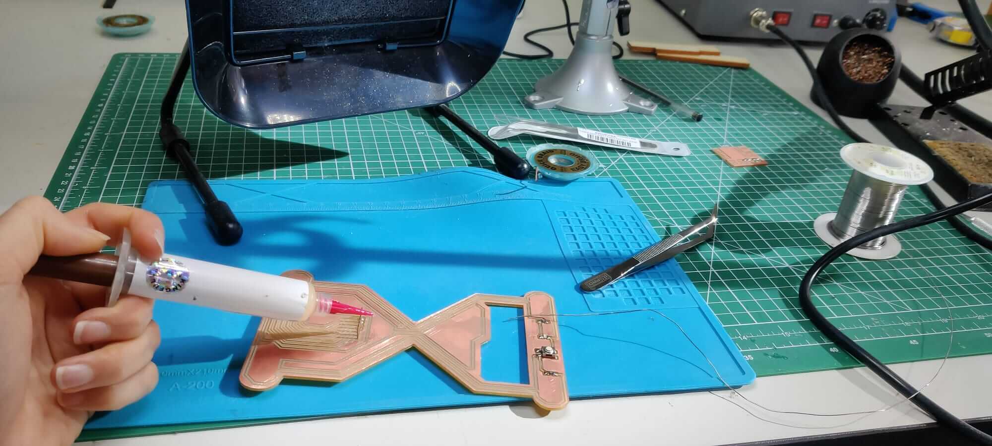
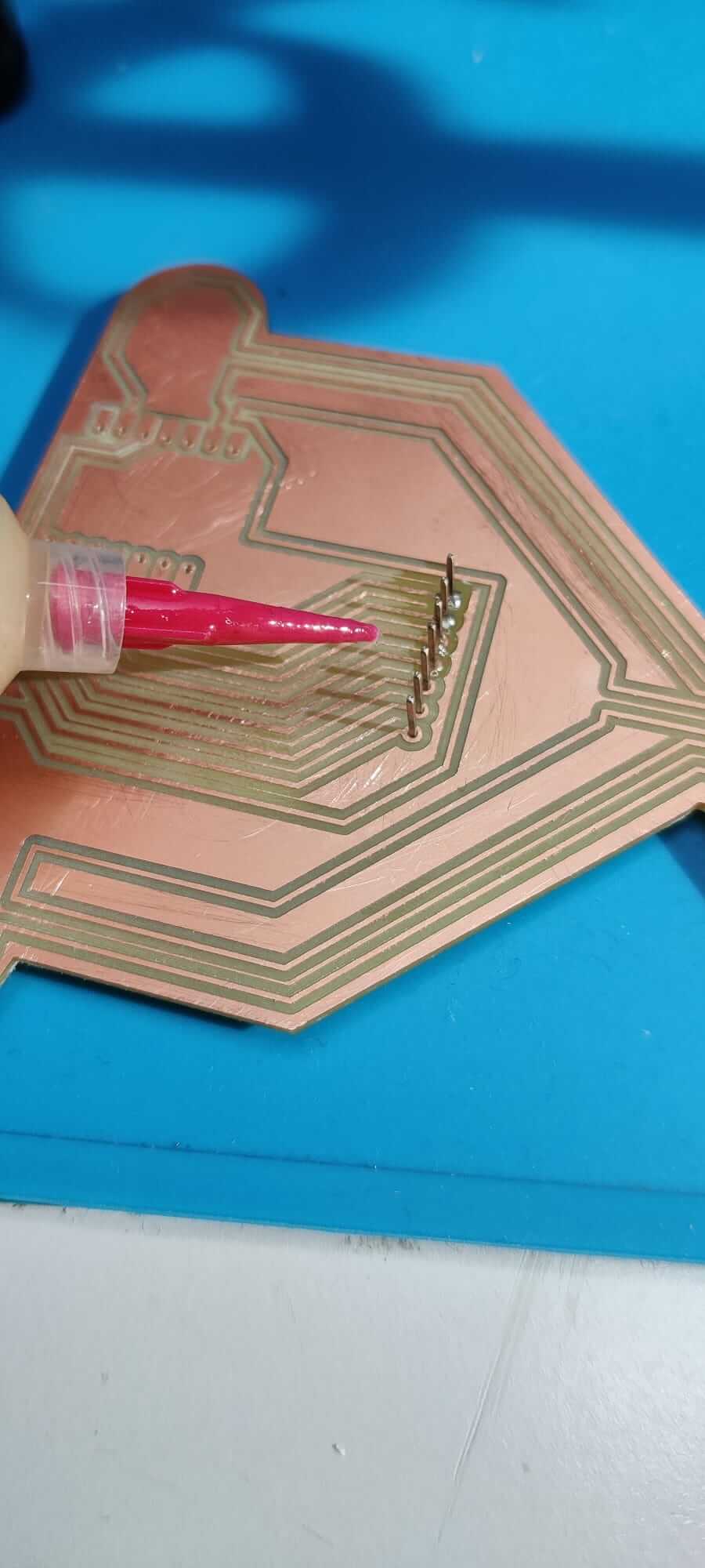
The flux can help in the welding process, but you have to pay attention to the corrosion property of the flux, and proceed to clean the board with alcool after the welding process.
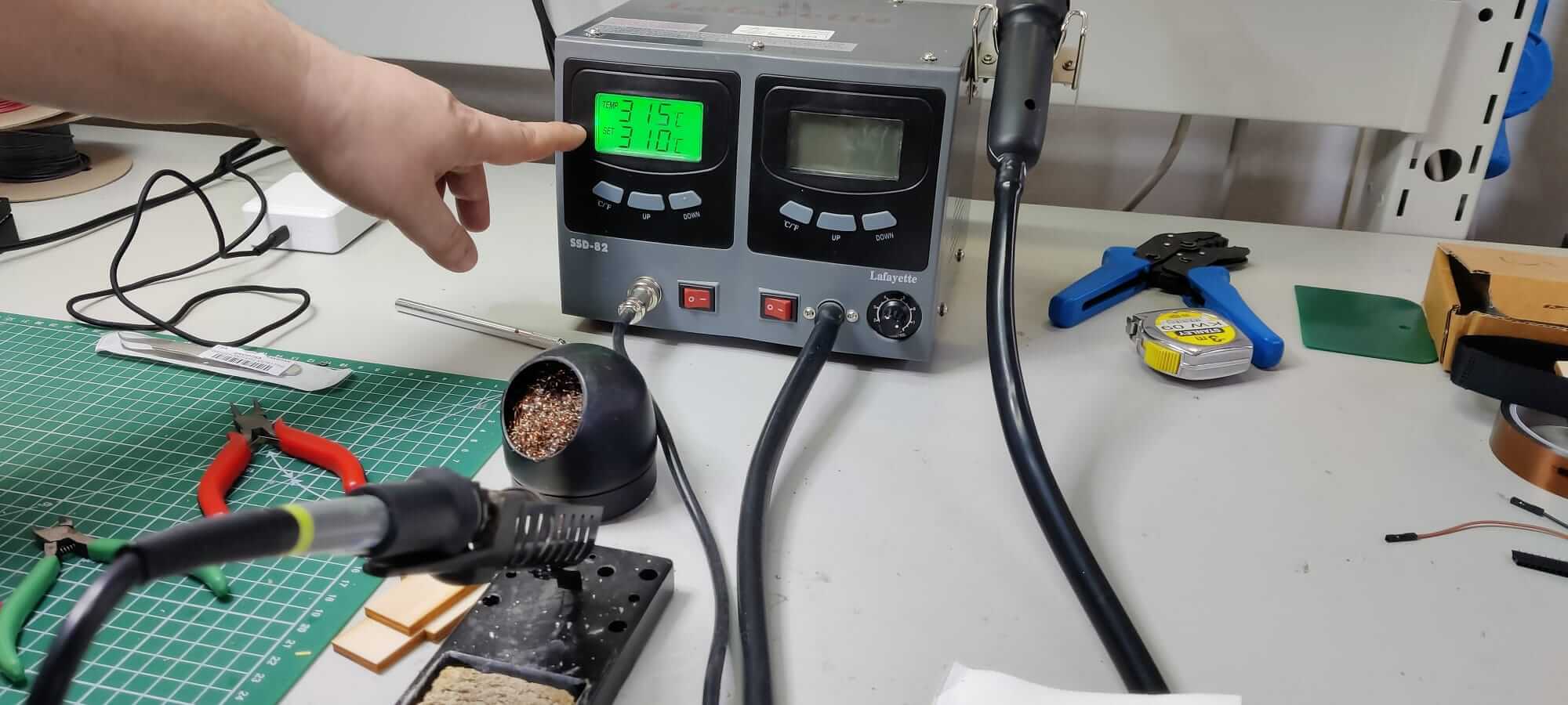
The temperature for a good copper welding is 310°C, a well done welding should be shiny and smooth. Remember to shut off the welding tools when you walk away!!!
I started soldering my glass hour PCB. First of all, I selected the compoments present on my PCB. Using the right quantity of flux, soldering is not an hard task.