7. Computer controlled machining
add a picture here of the ShopBot machine available in SantaChiara Lab
Assignments
group assignment
Do your lab's safety training.
test runout, alignment, fixturing, speeds, feeds, materials, and toolpaths for your machine
Individual assignment:
Make (design+mill+assemble) something big (~meter-scale)
extra credit: don't use fasteners or glue
extra credit: include curved surfaces
For my individual assignment, I have decided to I decided to create a small storage cabinet with a 3 storage plan: one at the bottom, a central one and an upper plan.
In terms of spatial constraints (this piece of furniture is intended to be positioned in the lunch area of the fabcademy premises in Siena):
Step by step ceration of this storage furniture with Fusion360.
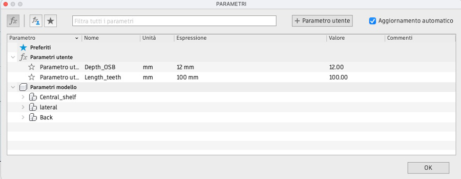
To begin with, creation of one key parametric element: the depth of the OSB pannel that we are using.
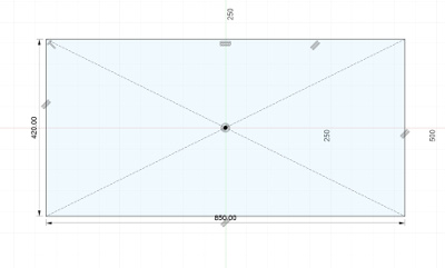
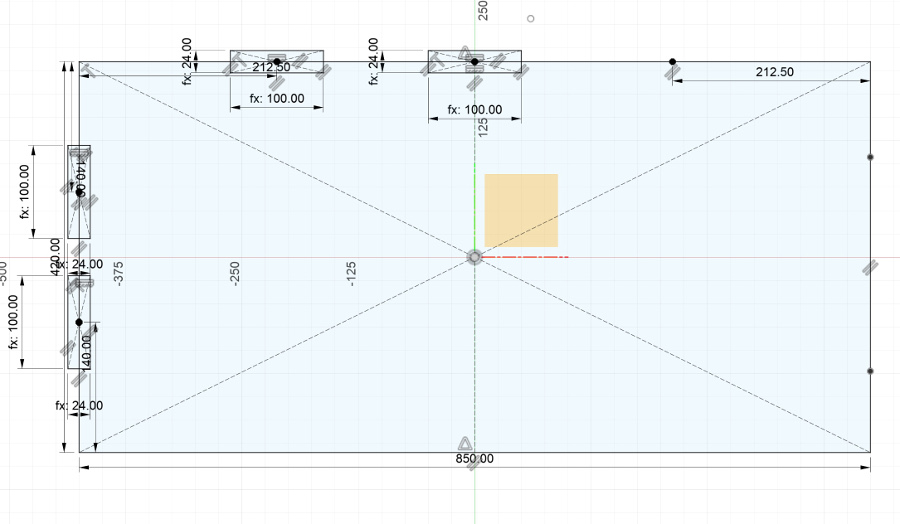
Considering the maximum dimensions that we have set ourselves, creation of the basic rectangle that will constitute the shelf of the furniture.
The shelf dimensions are: 420 mm depth x 850 mm width.
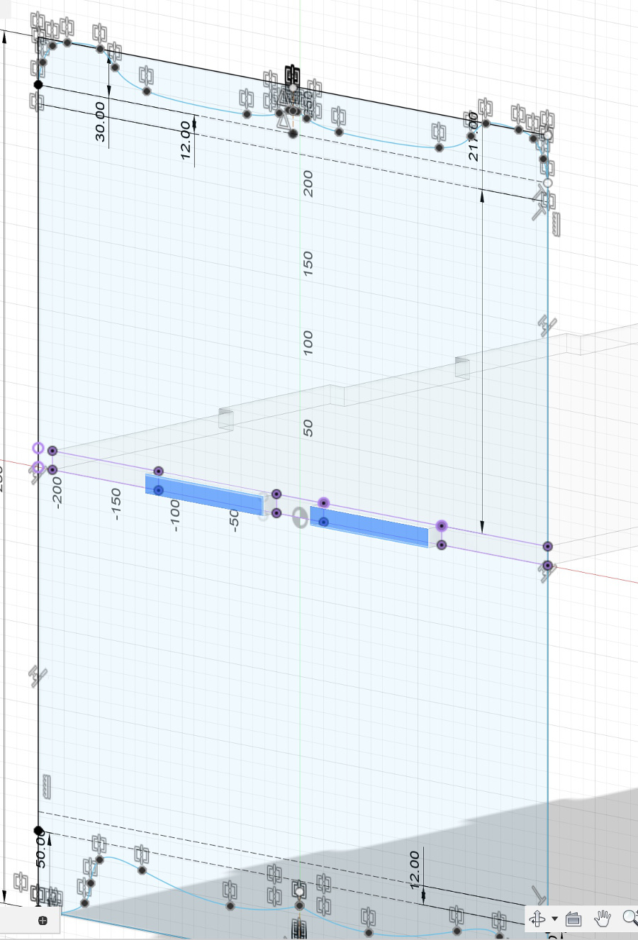
Creation of some reference points on which we will create the anchor areas between the different pannels of the storage cabinet:
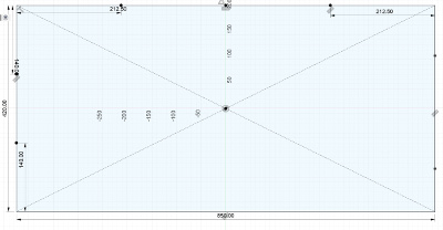
Preview of the creation of the mounting slots on the left side of the shelf.
Note the use of the pamaters Length_teeth and Depth_OSB multiplied by 2 getting to 24 mm for the mounting slots.
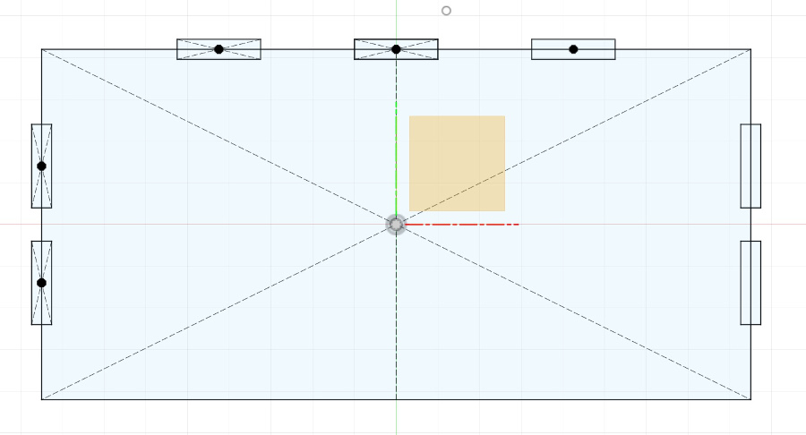
The left hande side element are replicated on the right side using the symetry tool.
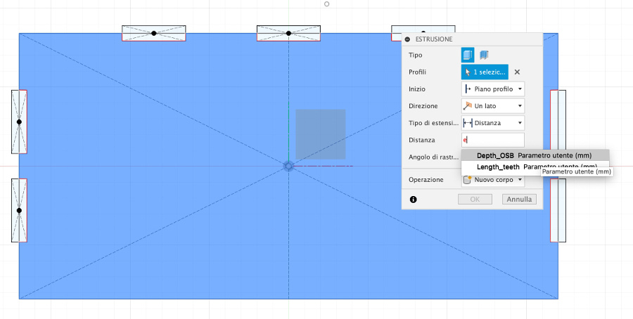
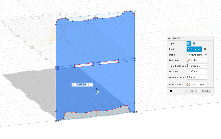
Extrusion using the parameter created for the depth of the OSB pannel (Depth_OSB).
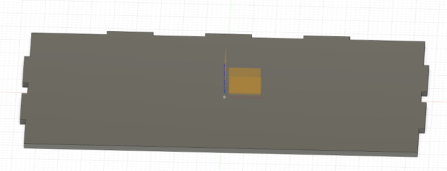
After extrusion, the shelf looks like this:
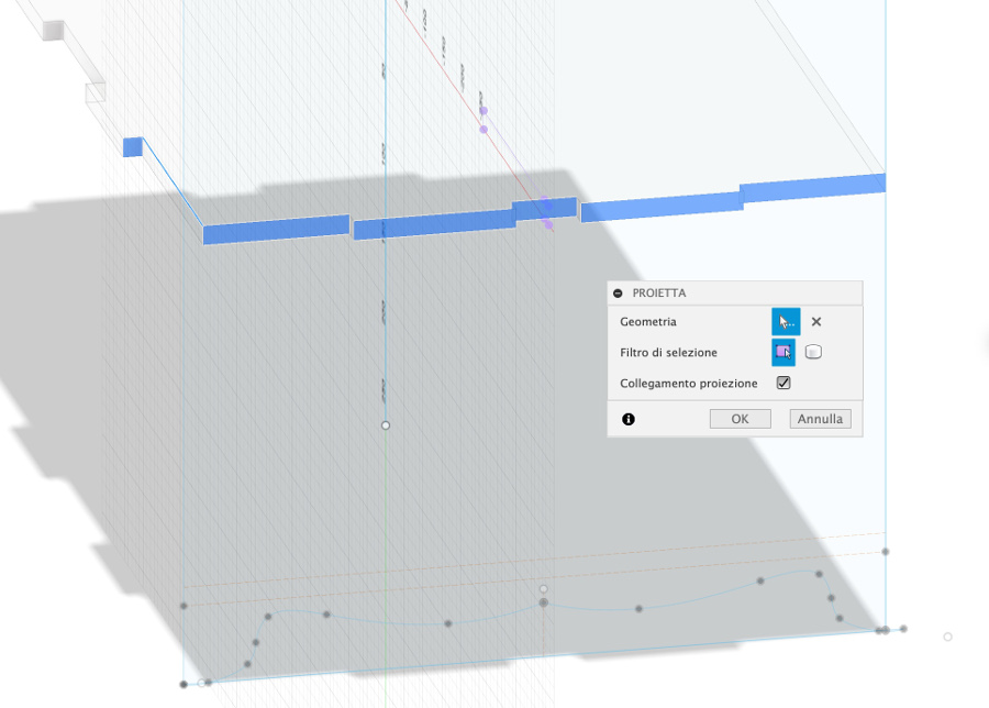
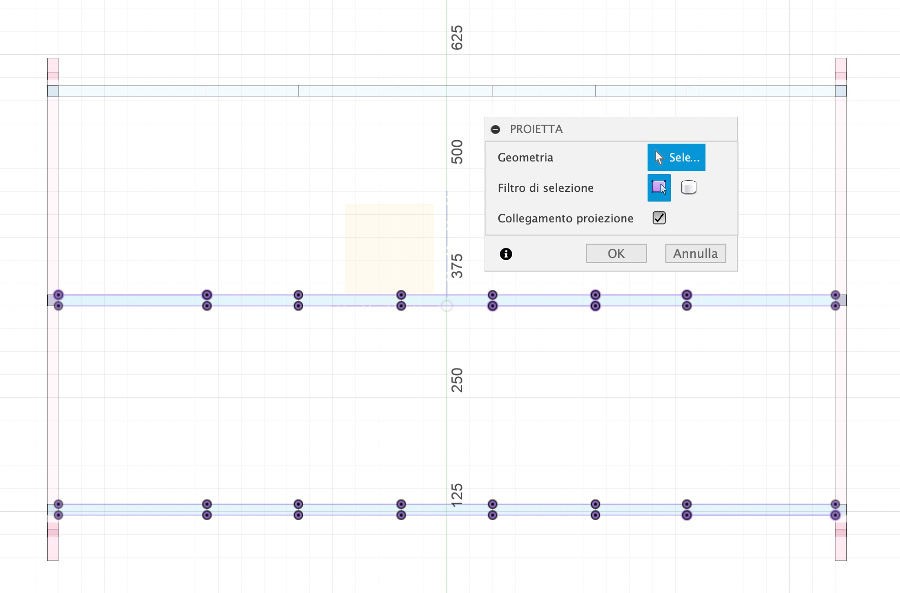
Use of the projection tool:
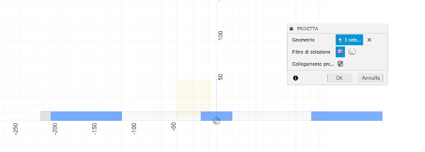
Result of the projection:
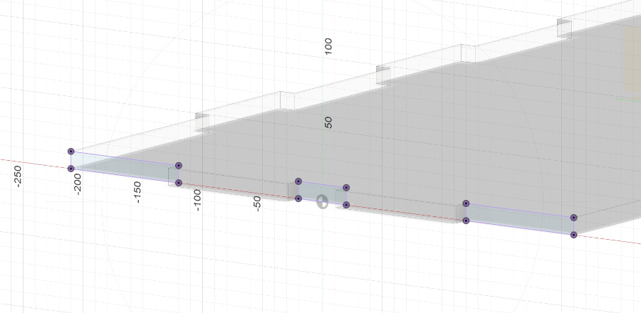
img12:
Viw of the left pannel of the storage cabinet:
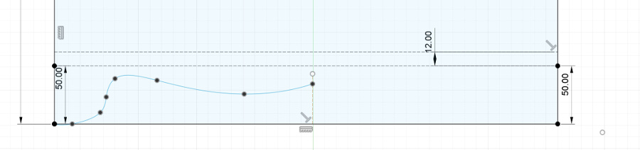
creation of a geometric shape made from curves to decorate the lower part of the furniture.
This curve is created only for one half of the pannel.
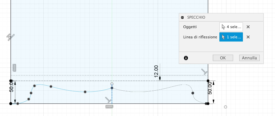
The shape created on the left side is mirrored on the right side ensuring full symetry:
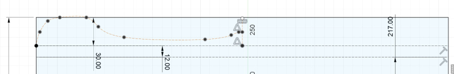
Similar type of curve creation is done for the upper part of the furniture.
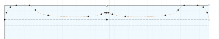
The shape created on the left side is mirrored on the right side ensuring full symetry:
:
view of the left panel of the cabinet as well as of the central shelf with the fitting points:
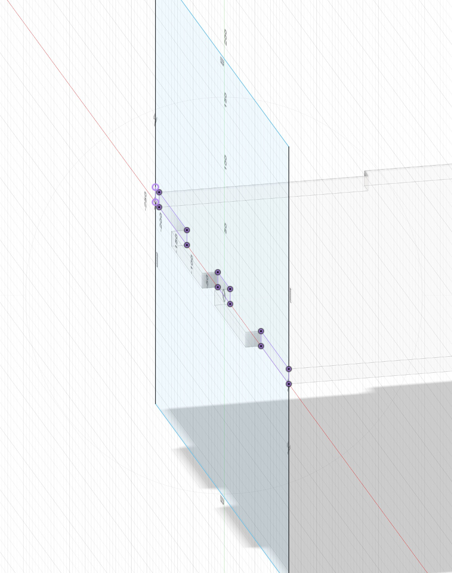
Projection of all side faces on the edge of the shelf:
Extrusion of the shape using the Depth_OSB parameter defined.
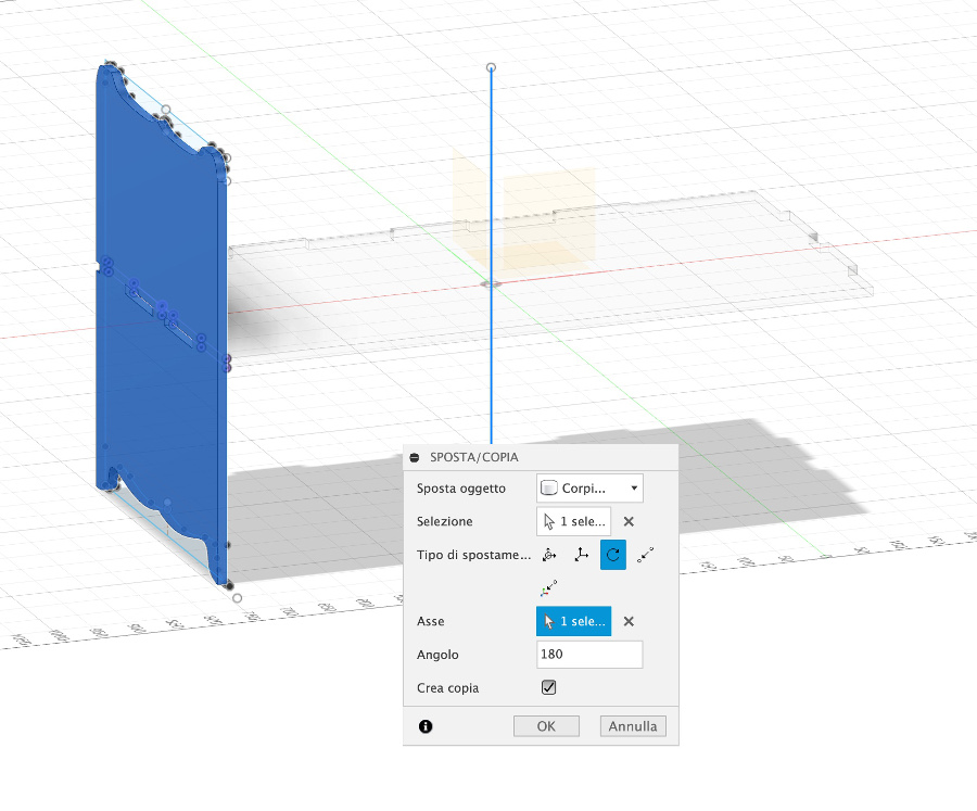
Copy of the left pannel of the cabinet using a 180 degres rotation:
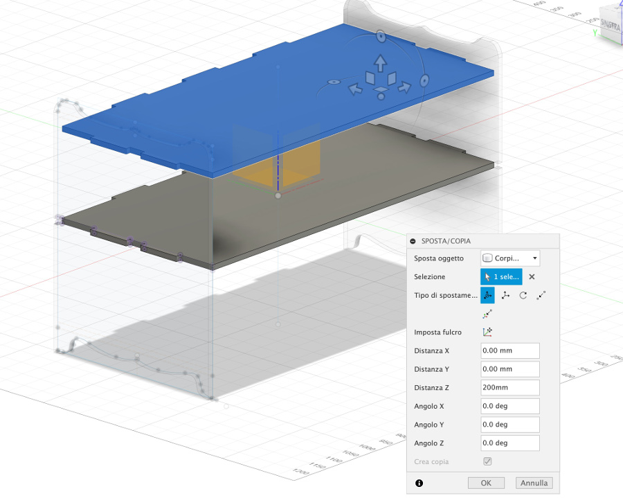
creation of the shelf on the lower part by copying the first shelf created and translate it down:
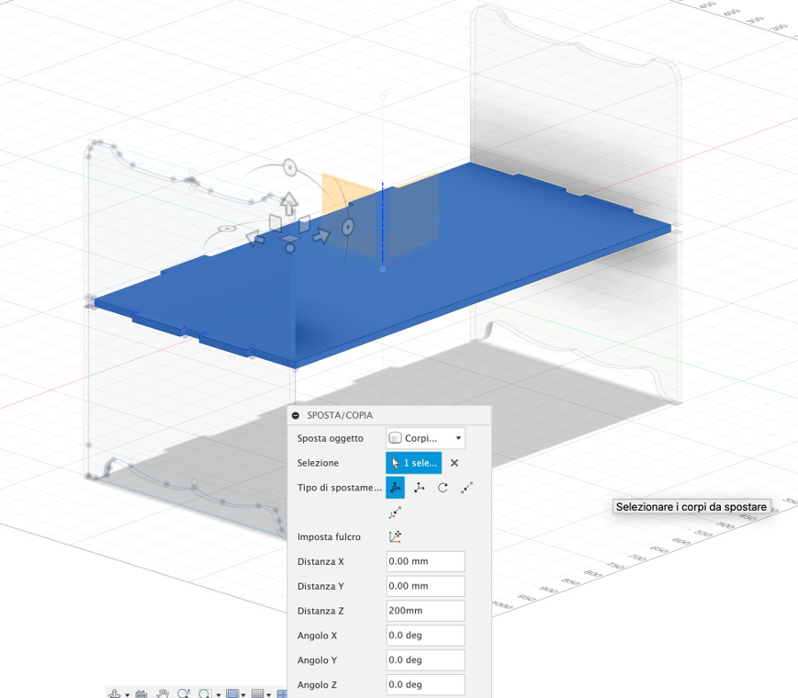
creation of the shelf on the upper part by copying the middle shelf and translate it up:
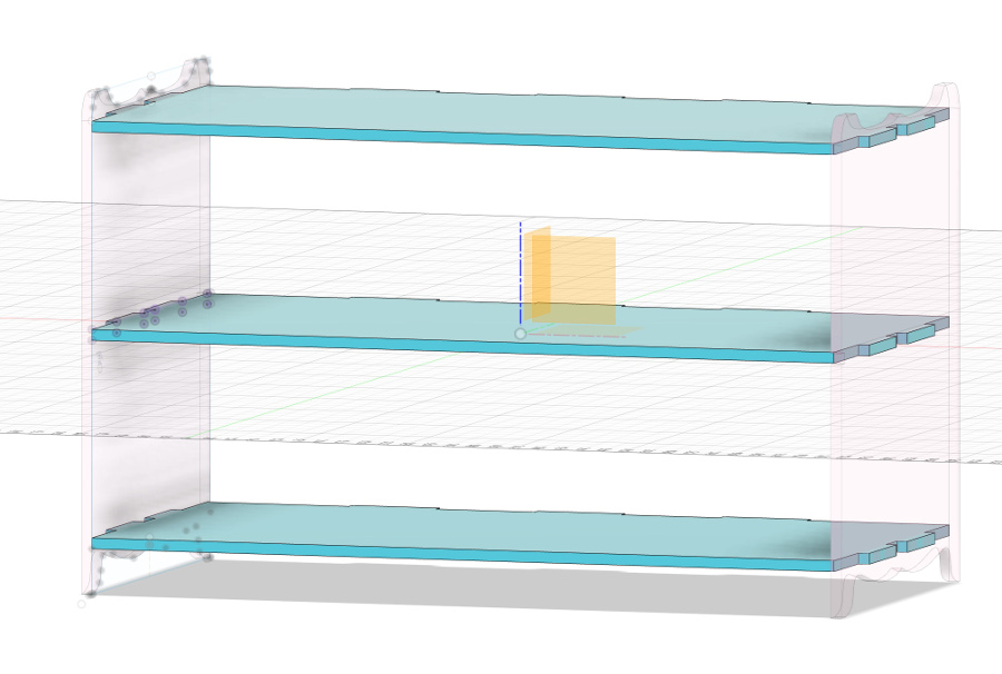
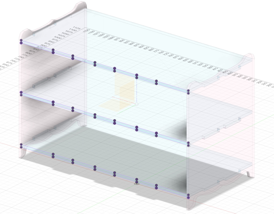
Front view of the cabinet with the 3 shelves and 2 lateral pannels:
Rear view of the cabinet. Rear pannel still need to be created to give strength and resistance to the diagonal sollicitations.
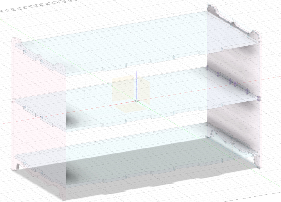
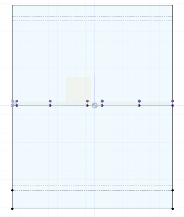
Use of the projections before creation of the rear pannel:
Use of the projections before creation of the rear pannel:
 "Storage_cabinet .f3d file download
Preparation of the work for the CNC machine:
The .f3d file created with Fusion 360 is exported of different in .dxf format (one .dxf file for each component).
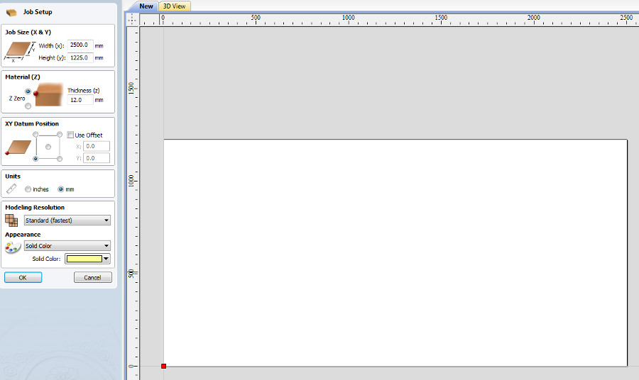
Next step consist in the transformation of these 3 .dxf files into GCode files. To do that, I used the software VCarve PRO from Vectric corporation.
Set-up of the dimensions: x,y and z
OSB sheet characteristics: 12 mm depth, dimensions: 2500 mm x 1225 mm
Set-up of the origin: low, left part.
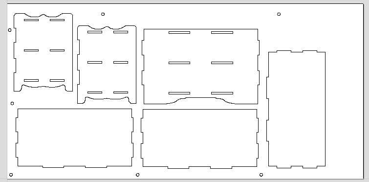
Import and positioning of all the .dxf files (3types)
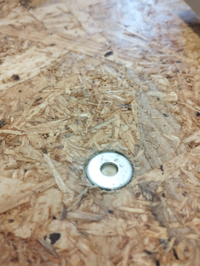
Definition of the circles that are the fixation points of the OSB sheet. These circles have a diameter of 20 mms and a depth of 2.5 mm (to insert the washers).
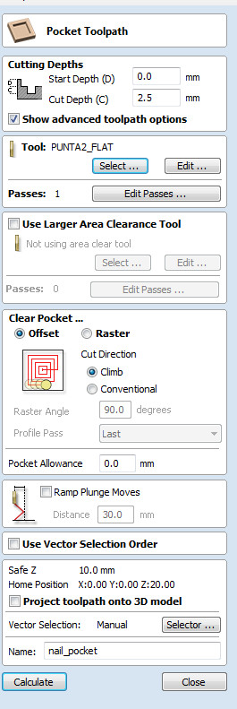
Set-up of the Pocket Toolpath.
selection of the toolbar
Number of #passes to create this pocket Toolpath: 1 is enough.
Clear pocket: selection of the best movement strategy. in our case, offset sounded the more appropriate (in this case the tool moves from the center to the external parts.
In case "raster" would have been selected for the clear pocket, the tool would move from one horizontal line to the next one.
in the end, I have given a name to this pocket toolpath: nail_pocket
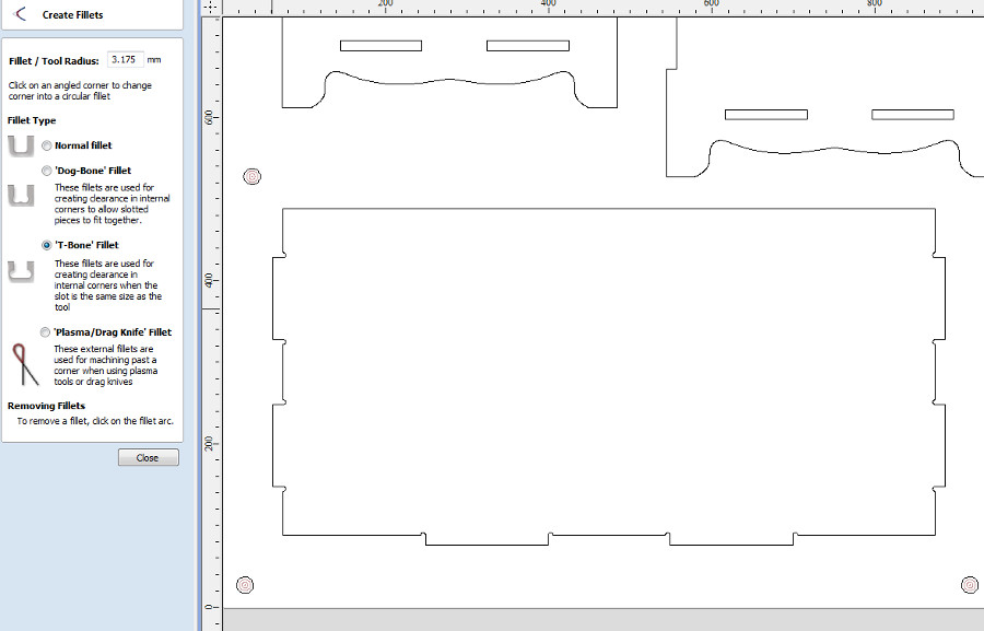
Creation of the filets of a diameter of 0,25" (3,175 mm)
Without these filets it would be impossibile to assemble the different elements.
in this phase, we created filets on every angle that required it.
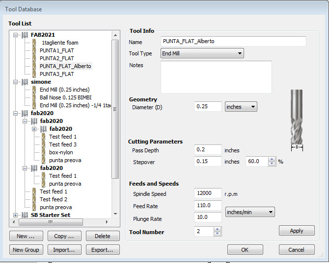
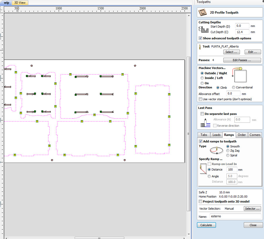
Set-up of the parameters of the tool:
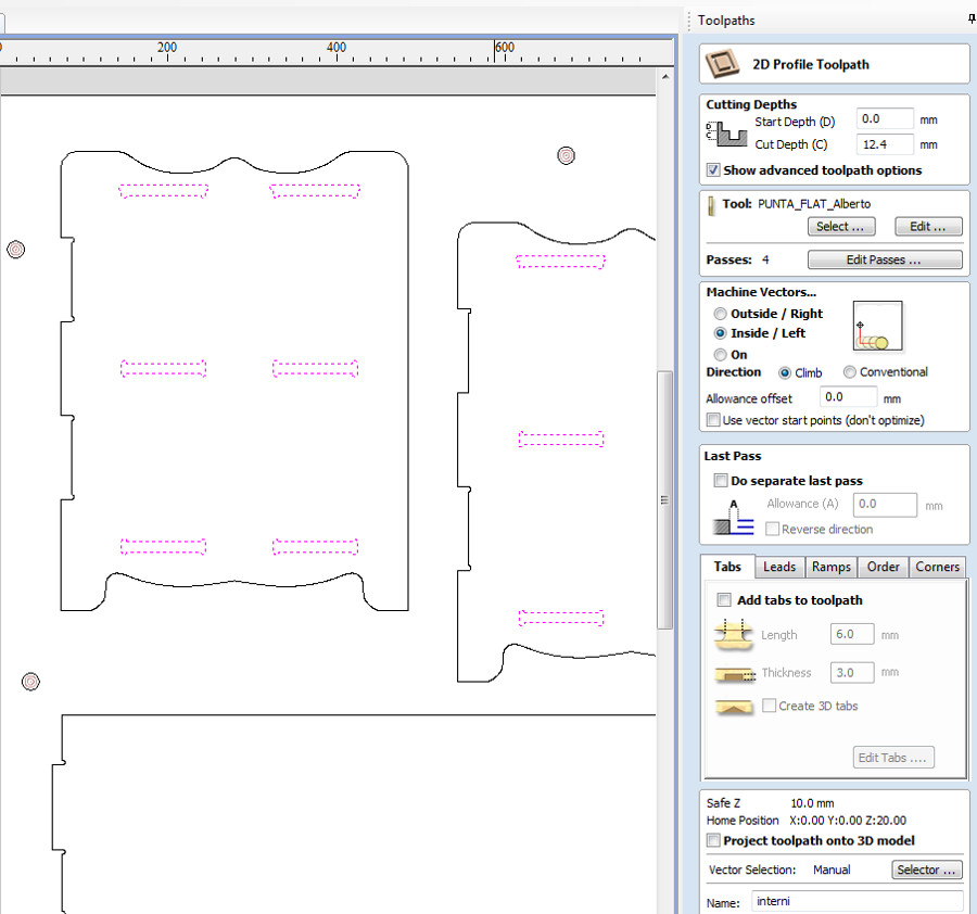
Selection of all the internal geometries (in pink) since they have to be elaborated first.
Selection of toolpath type: 2D profile Toolpath.
Cut Depth: 12.4 mm (slightly greater than the OSB depth to ensure that all elements are cut and will be detached from the sacrifical layer in MDF.
Number of passes: calculted automatically using the pass depth and the OSB depth, in this case 4.
Machine Vectors: 3 options available. "Outside", "Inside", "On". In our case, selection of option "Inside"
operation for all the perimeters of the components
Selection of the option "outside" for the machine vector.
Flag "add ramps to toolpath" to limit the stess on the tool.
creation of the tabs (in yellow) to maintain the pieces in position (2mm depth x 8 mm length) after cut operations.
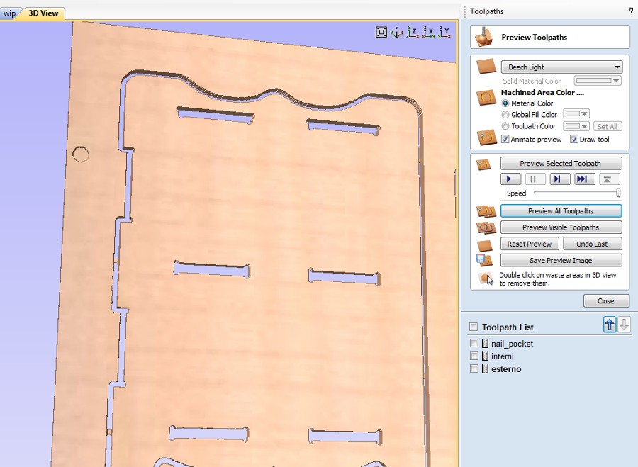
Overview of the tabs and filets:
Preview option: with the possibility to review and zoom on all the areas. This preview option is crucial to check that the tool will never reach the areas where the pockets have been placed.
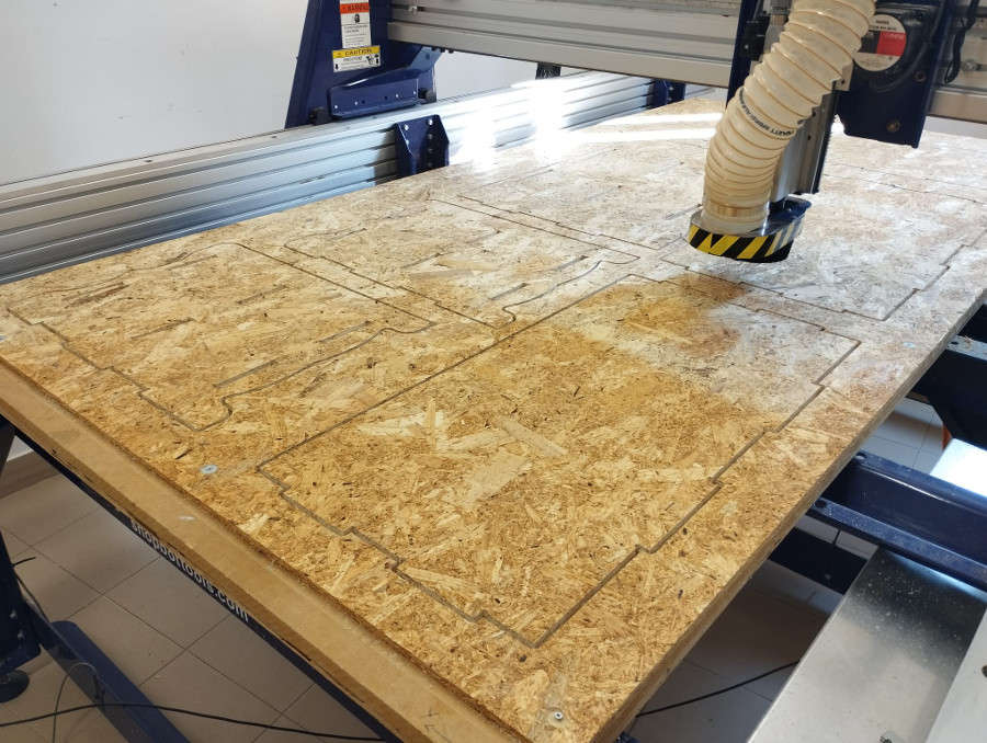
Milling the conponents of the cabinet
The CNC machine that I have used is a ShopBot model PRSstandard.
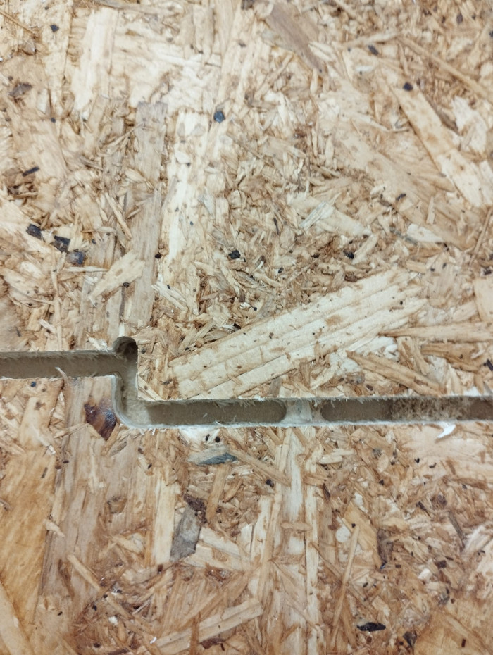
First step: milling of the Pocket Toolpaths of a depth of 2,5 mm:
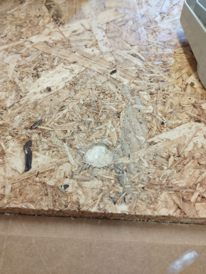
Second step: positioning of a washer in each Pocket Toolpath milled:
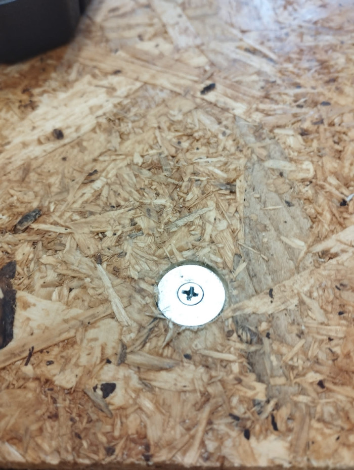
Third step: fixing of the OSB sheet on the MDF sacrifical layer using screws:
Fourth step: milling of the internal elements:
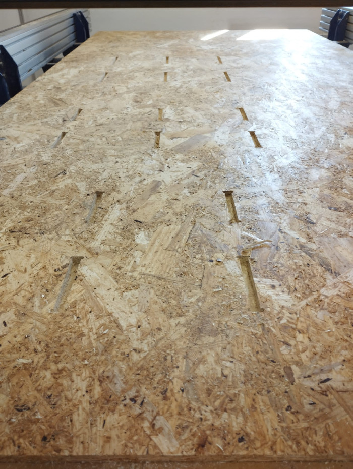
Fifth and last step: milling of the outline of the elements:
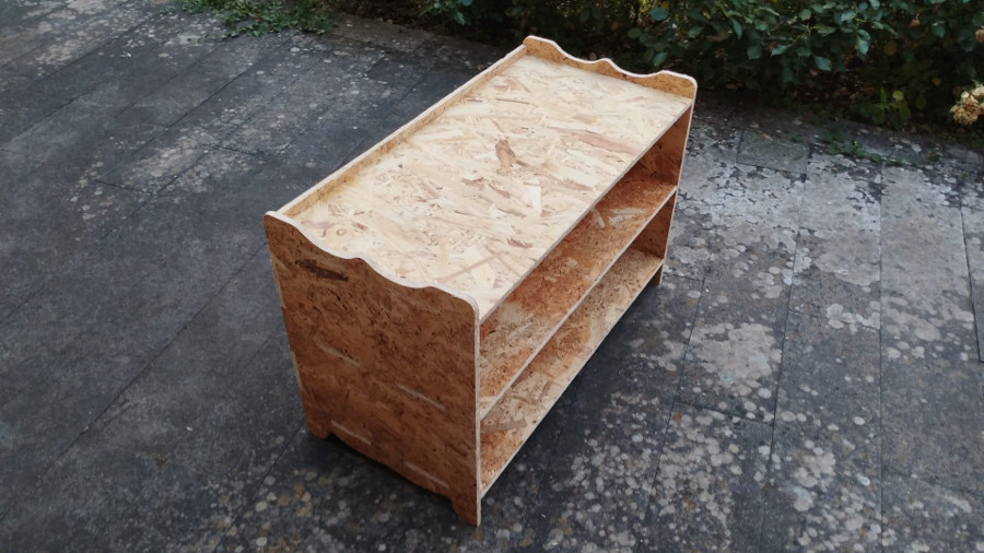
Assembling of the different elements of the cabinet
Before starting the assembly of the different elements, the edges of each of the panels were carefully sanded to facilitate assembly and give a prettier finish.
No glue nor screws have been used to assemble the cabinet.
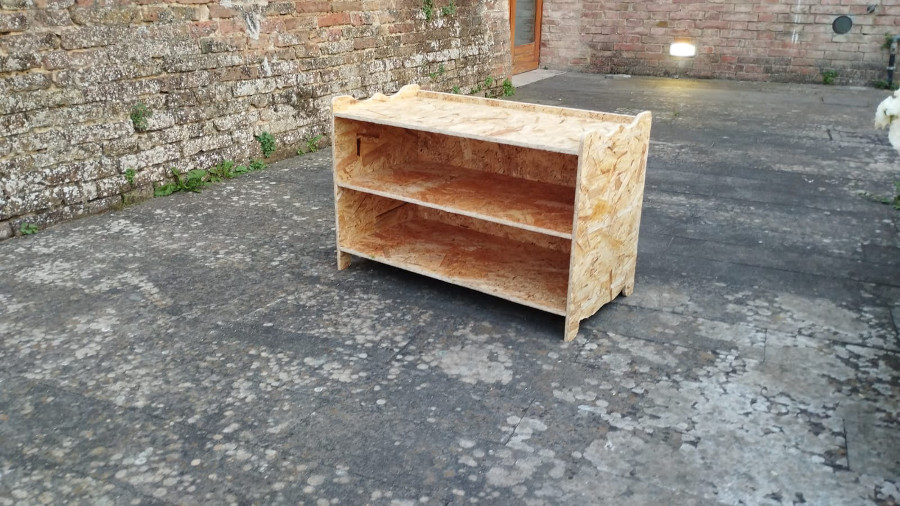
Result at completion of the mounting activities of the cabinet:
(photos taken in the courtyard in front of the carpentry of the SantaChiara Lab).
Lateral view:
Rear view:
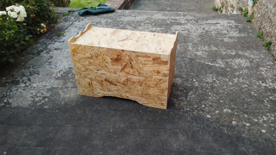
Front view: