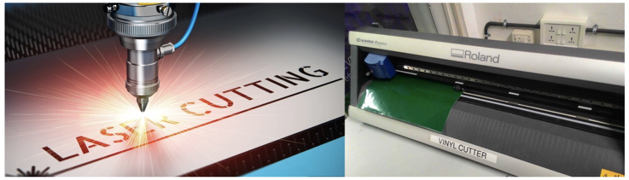
3. Computer controlled cutting
Assignments:
Group assignment:
Characterize your lasercutter's focus, power, speed, rate, kerf, joint clearance and types
Individual assignment:
Cut something on the vinylcutter
Design, lasercut, and document a parametric construction kit:
And for extra credit include elements that aren't flat.
Parametric construction:
Evaluation of the Kerf:
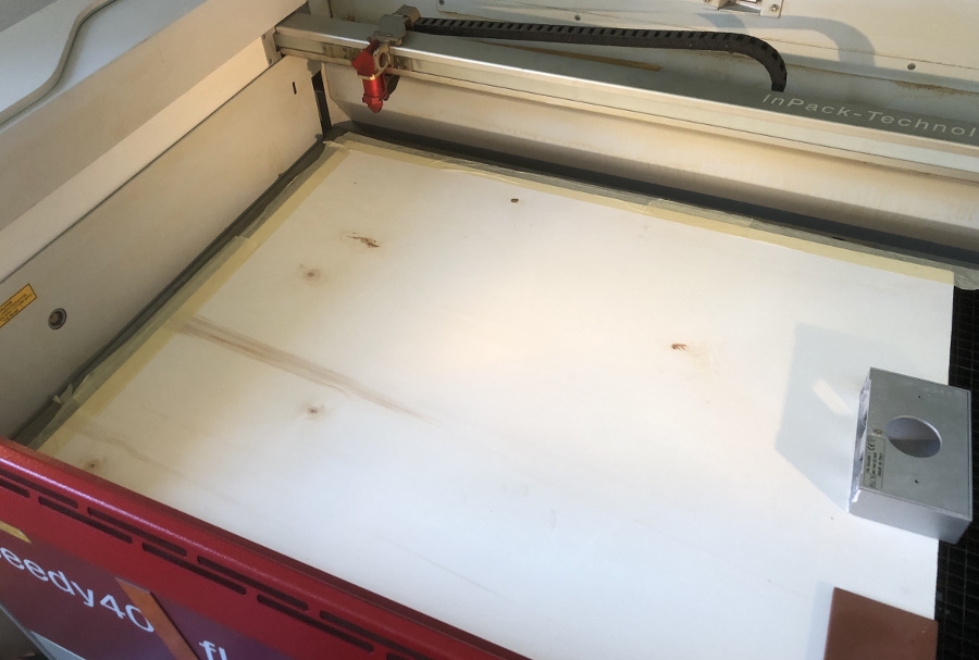
Photo of the material that I will be using for this assignment: compensated wood of approximately 2,9 mm depth.
This type of material is not perfectly flat because it is subject to the effects of humidity or the dryness of the air in the places where it is stored.
Nor is its thickness perfectly equal if measured at different points around its perimeter.
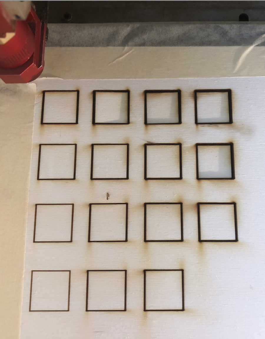
First attempt to cut a set of 16 squares of 20 mm per 20 mm changing the speed and the power of the laser beam.
Results of the second and third test:
Second test:
Overview of the parameters and set-up:
 4 x 4 Matrix download
Results of the test:
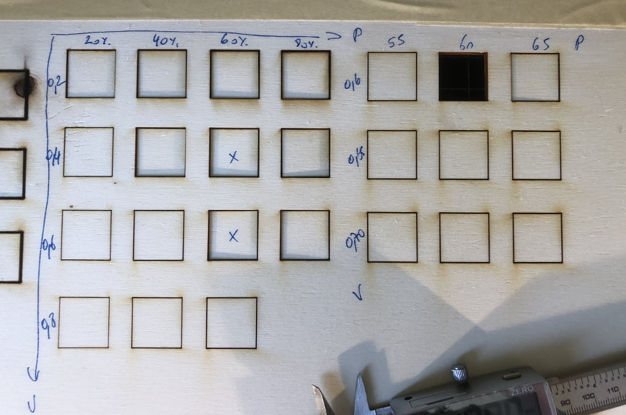
We deducted from the second test that a power of 60% and a speed of 40% and 60% gave the best resul in terms of cutting
This gave key indications to set-up the third test where:
From this experiment we can deduct that the best laser cutting results can be obtained using:
These are the results that we will be using for the "mass" production of our parametric components.
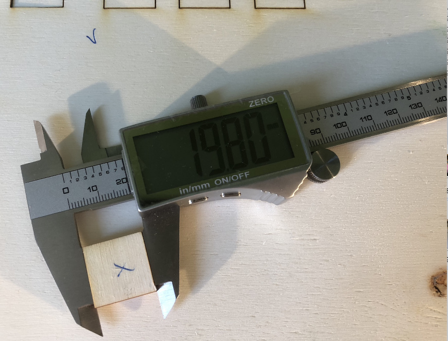
Evaluation of the Kerf:
The Kerf is evaluated after measuring on different samples the difference between the cut square and the theoretical measurement (20 mm)
in our case, after different tests (below 19,80mm), we concluded that the Kerk = (20,00 -19,80)/2 = 0,1 mm
Parametric 3D modelling:
The choice of the parameters which will be used is fundamental before any construction of the geometrical elements.
I have defined 2 key parameters that are:
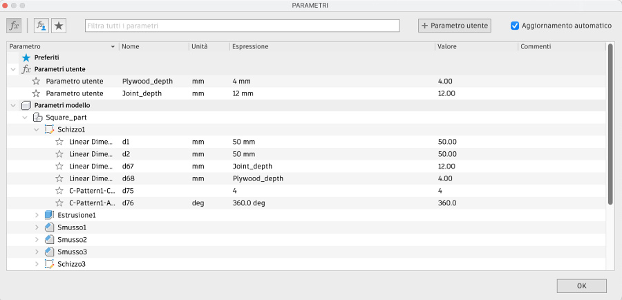
Having defined these 2 parameters, I started modelling the elements of the parametric construction kit using Fusion 360
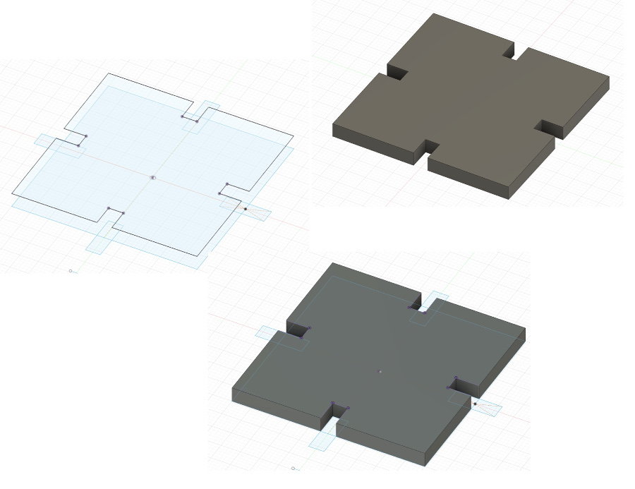
Rectangle:
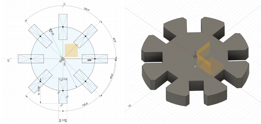
Circle:
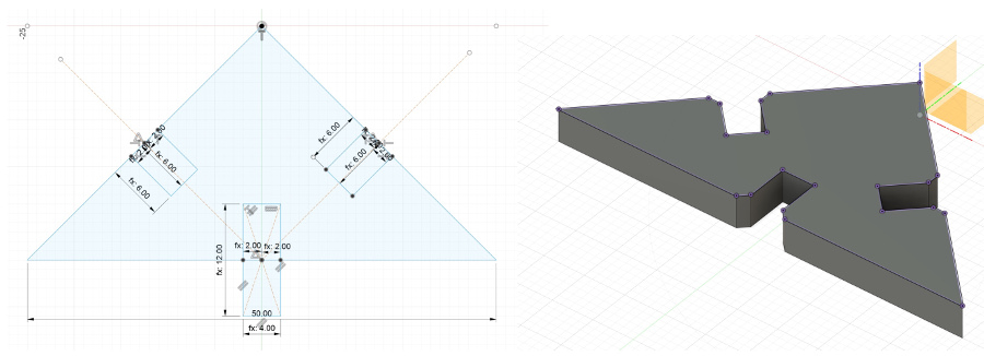
Triangle:
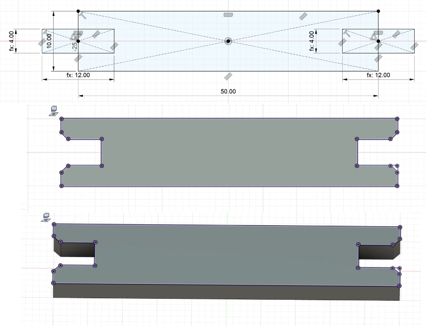
Joint:
Preparation of the file with the 4 elements:
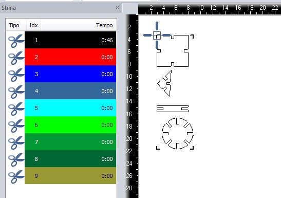
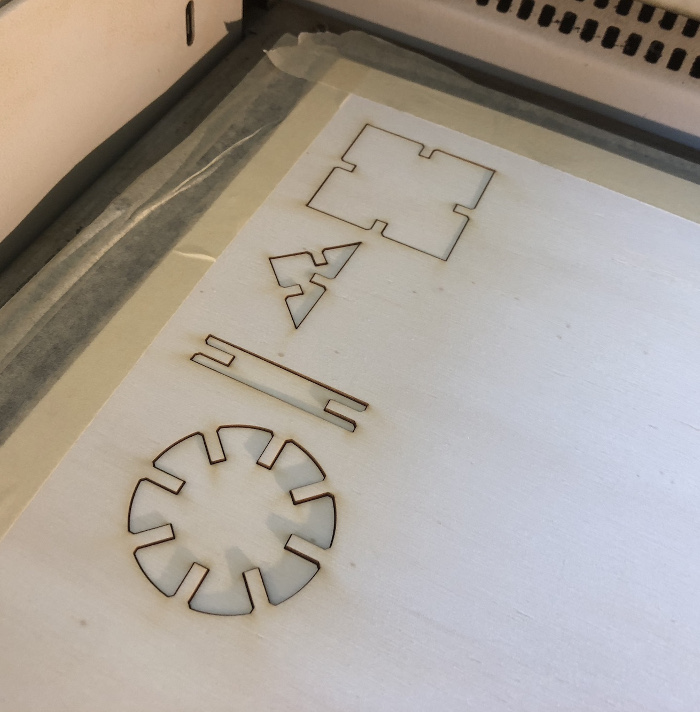
Uaing the previous file, first attempt to cut the 4 elements using the power (60%) and speed (60%) alonside with a kerf of 0,1 mm.
The operation went smoothly: after careful examination of the pieces produced, it can be seen that the edge of the elements is honey-colored that is the evidence of the good cut and confirms that the material has not been excessively burnt.
Considering the success of the previous step, a file has been prepared in Adobe Illustrator to fruitful the entire piece of plywood
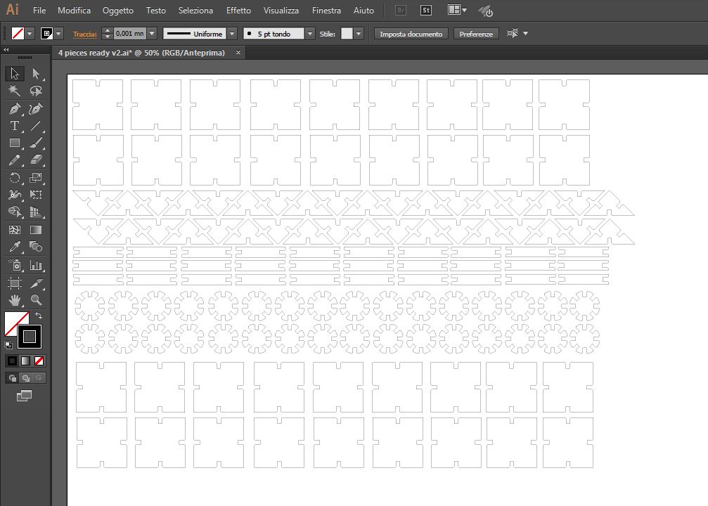 AI file - download Full layout with 4 elements
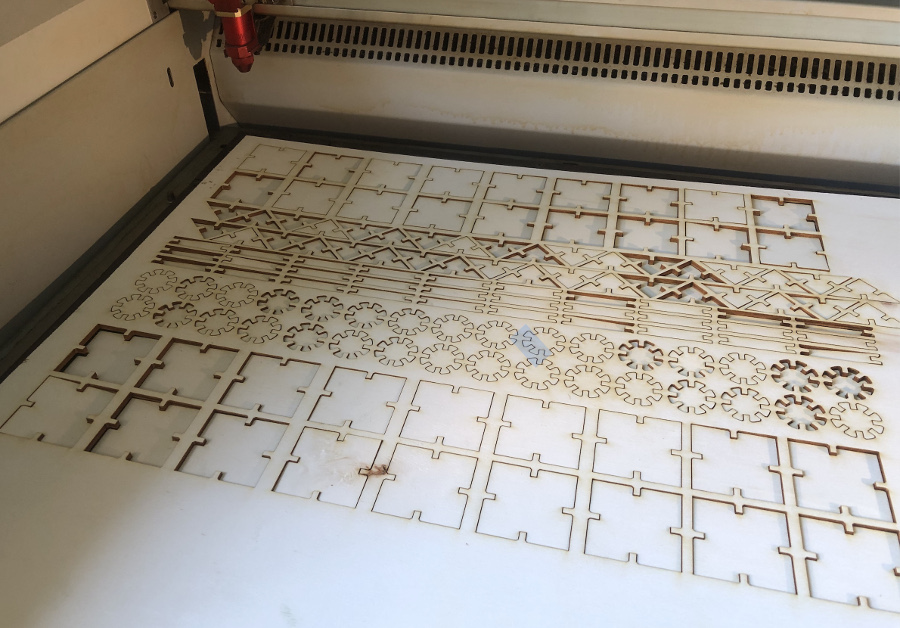
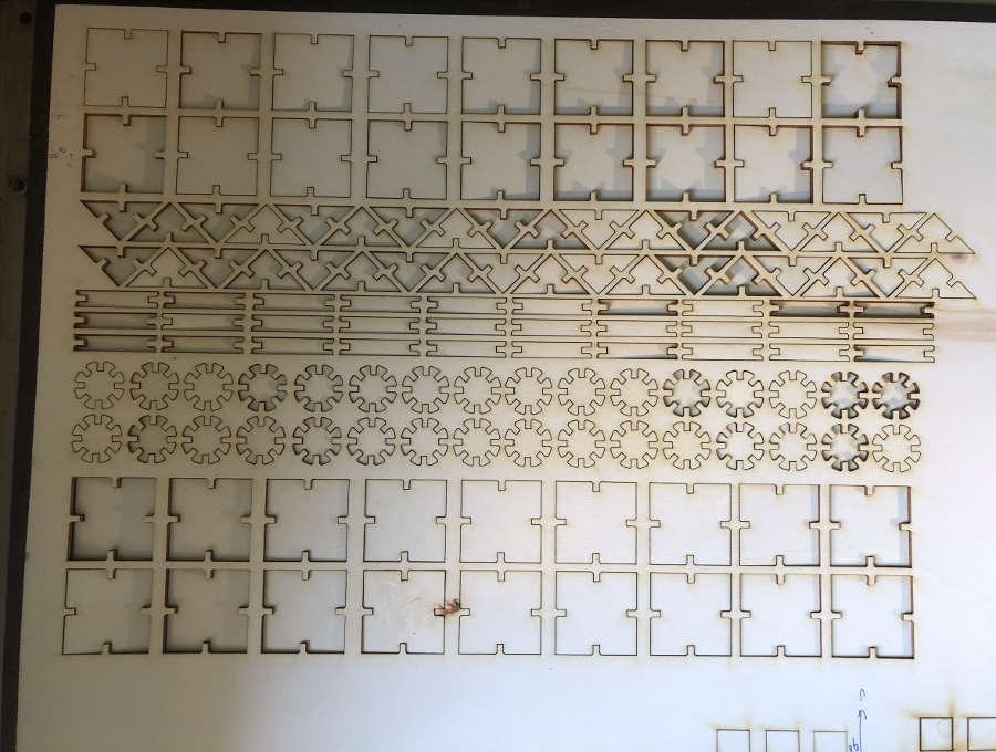
Elements after removal of the plywood frame:
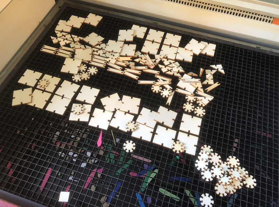
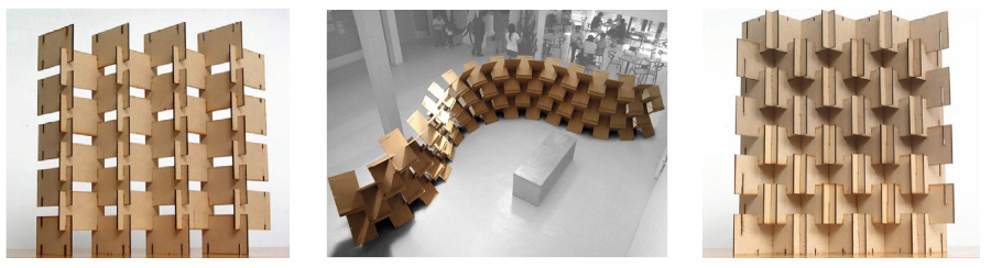
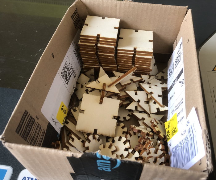
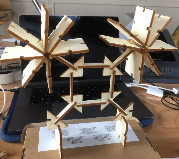
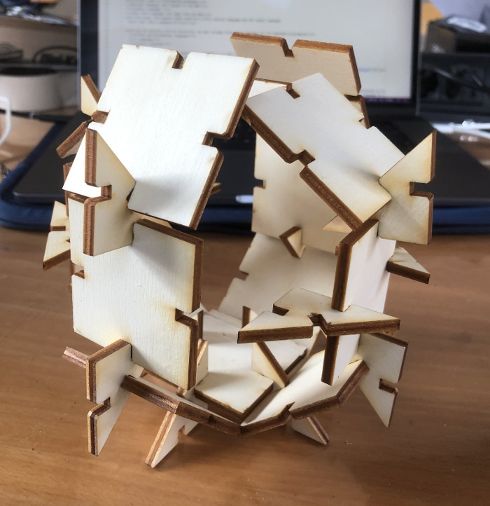
Kit ready for start the construction activities !
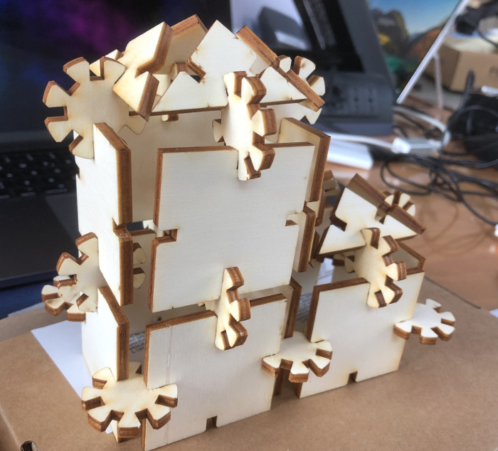
Here are some examples of assembly made with our components:
Parametric files (dxf format):
Vinyl cutter:
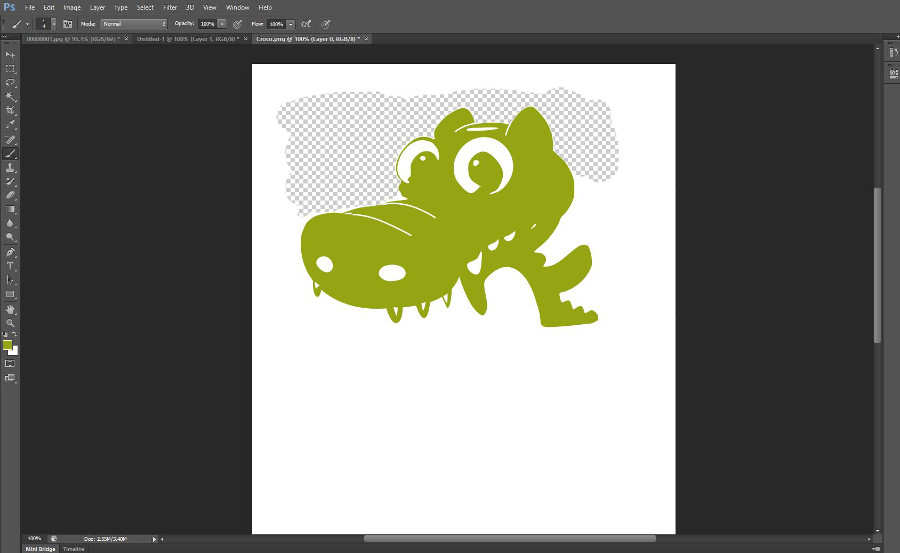
The idea is to make a cool sticker of a character that my wife and I really like.
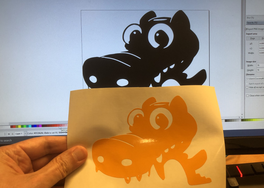
Let me introduce Commodo, a friendly commodus dragon

To get started with, I have launched the Inkscape tool and imported the dragon file in .jpeg format
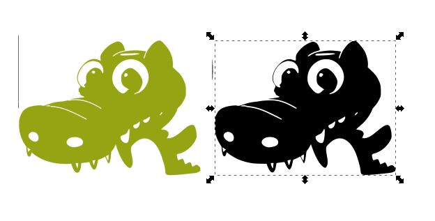
The whole image area was selectionned and from the main menu, selection of "Path" and "Trace Bitmap" to transfrom the image from raster to vector.
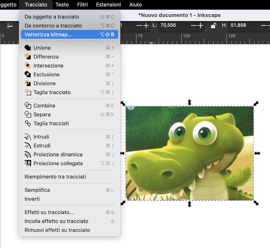
After pressing OK, the output contains 2 overlapping layers: the raster one and the vector one.
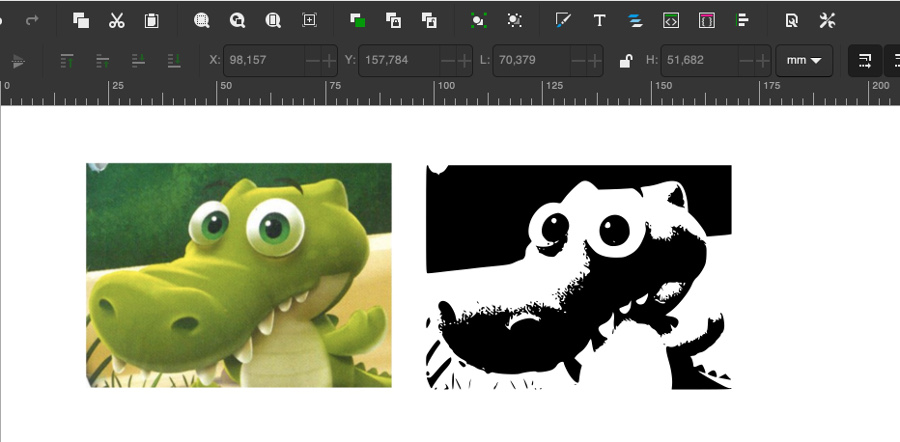
Separate the 2 items, select the raster one and cancel it.
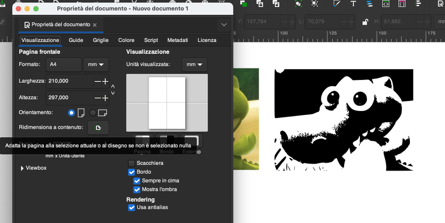
Then go to file, document properties to set-up the working area.
After that I have exported the file in .png format (Cairo .png to be precise)
The Inkscape file is not the most appropriate tool to operate deep graphical modifications, for this reason I have use Adobe Illustrator using the Cairo .png file generated by Inkscape
The graphical work has been focused on many areas and especially the left upper part that I wanted to remove.
At completion of the graphical revamping, I have exported the file in Cairo .pbg format
Import of the final graphical version of the .png file into Inkscape:
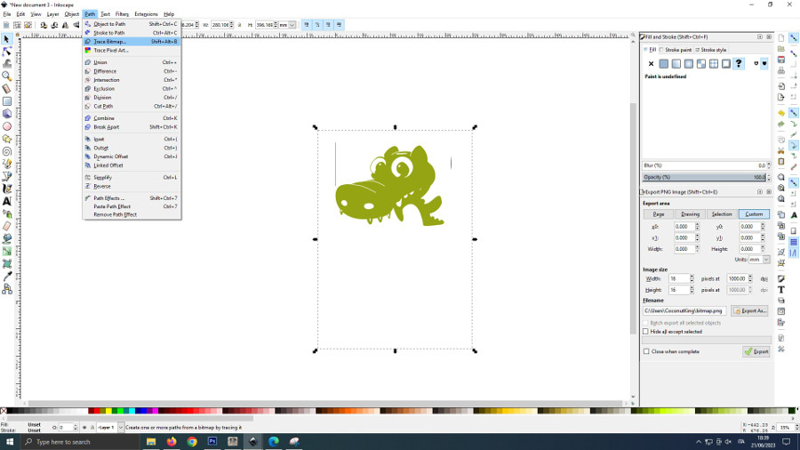
Menu "Path", "Trace bitmap",using the following options and press OK:
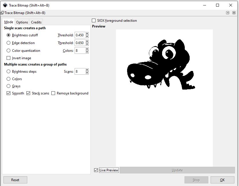
As previously explained, we have 2 layers generated (the raster and the vector one). Remove the raster element before proceeding:
Select the vector element and go to "File", "document properties" to set-up the working area.
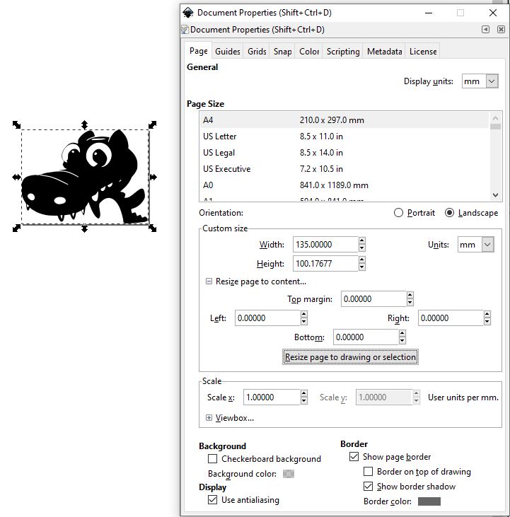
Image outline and extraction of contours:
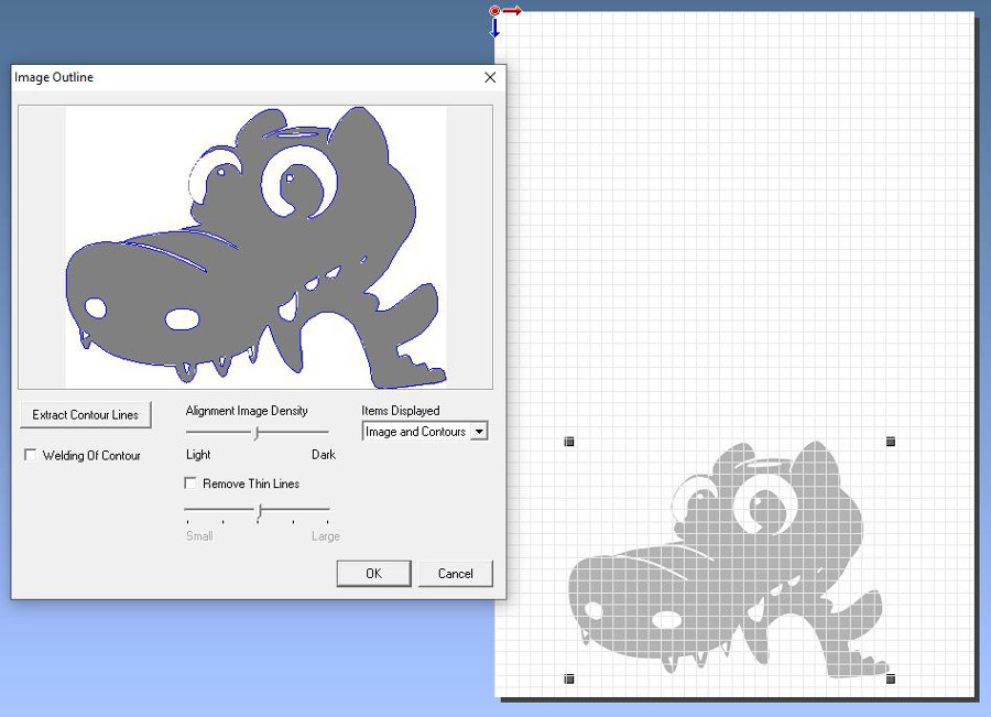
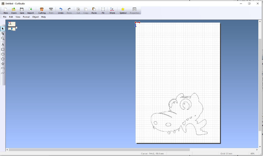
Our dragon in vector format with only the coutours is ready:
The vinyl cutter used in the Santa Chiara lab is a Roland CAMM-1 GS-24.
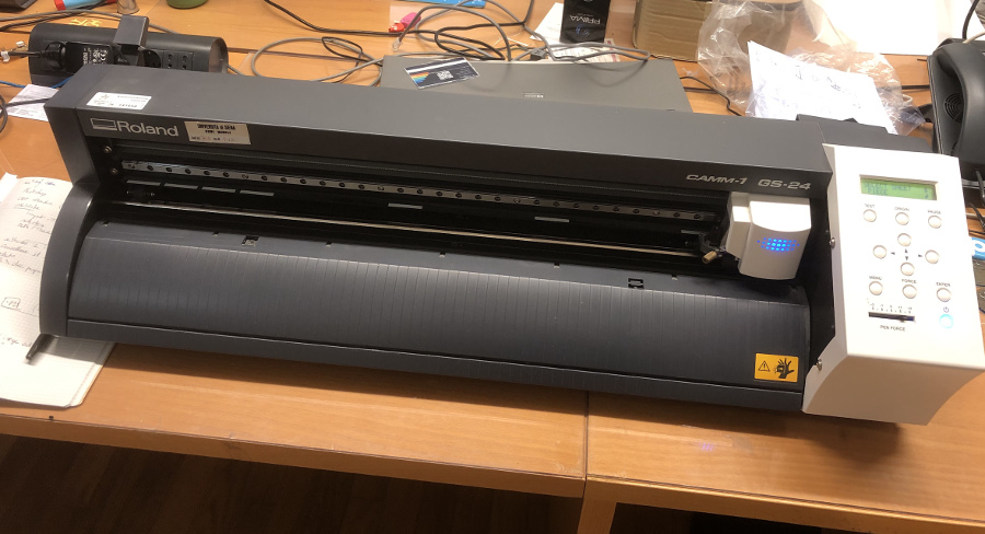 Technical specifications of the Rolland CAMM-1 GS-24
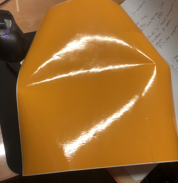
The vinyl material that we will be using to produce our dragon sticker:
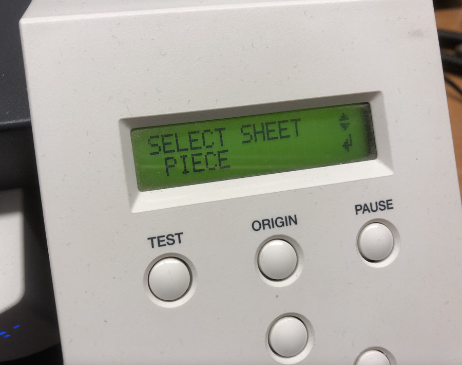
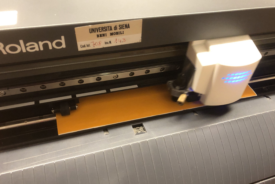
Loading of the piece of Vinyl into the machine:
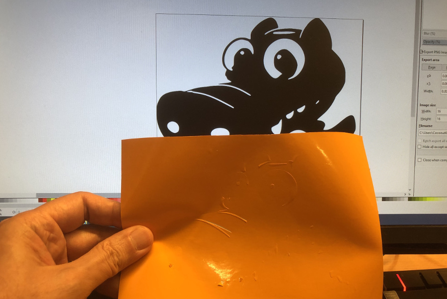
Completion of the Vinyl cutting operations:
Where is our dragon hidden ? We see some cur lines...
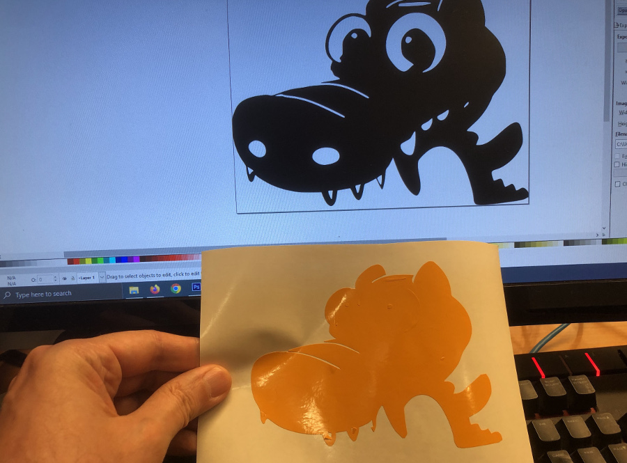
After removal of the envelope of the sticker, things are getting clearer ;-)
After last removal of the last pieces (eyes, noise), here we are with our Commodo sticker !