2. Computer aided design

Computer-Aided Design (CAD) is a technology that enables the creation, modification, and optimization of designs using computer software. It is widely used in various industries, including engineering, architecture, industrial design, and manufacturing. CAD systems provide a digital environment where designers can create and manipulate geometric models of objects or structures.
CAD software allows designers to create precise and detailed 2D and 3D models of their designs. These models can be visualized from different perspectives, rotated, and examined from various angles. CAD tools provide a range of features and tools to aid in the design process, such as drawing tools, modeling primitives, parametric modeling, and assembly capabilities.
With CAD systems, designers can efficiently explore different design options, make modifications, and analyze the performance and behavior of their designs before they are physically built. CAD software often includes simulation and analysis tools that allow designers to test the structural integrity, motion, thermal properties, and other aspects of their designs virtually.
CAD models can be easily shared, modified, and reused, allowing for collaboration between designers and engineers. The use of CAD significantly improves the efficiency and accuracy of the design process, reduces errors and rework, and enables faster prototyping and manufacturing.
Overall, CAD plays a vital role in modern design and engineering workflows, providing powerful tools to create, visualize, and optimize designs, leading to improved productivity and innovation.
Assignments:
Model (raster, vector, 2D, 3D, render, animate, simulate, ...) a possible final project, compress your images and videos, and post a description with your design files on your class page.
Softwares for 2D modelling:
I have fruitfuled with weekly assignment to get finaliar with GIMP and use it in the re-sizing of the images.
GIMP is a free and open-source raster graphics editor used for image manipulation and image editing, free-form drawing, transcoding between different image file formats, and more specialized tasks.

Illustration of the steps required to resize a .jpeg image.
Drag and drop the file on the GIMP main window.
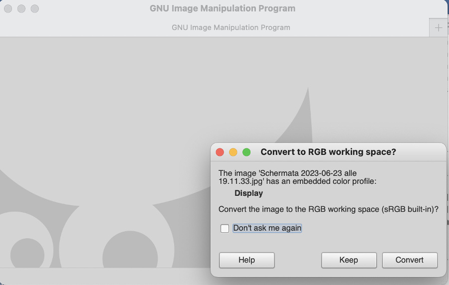
A window "Convert to RGB working space" pops-up, click on "Keep" button:
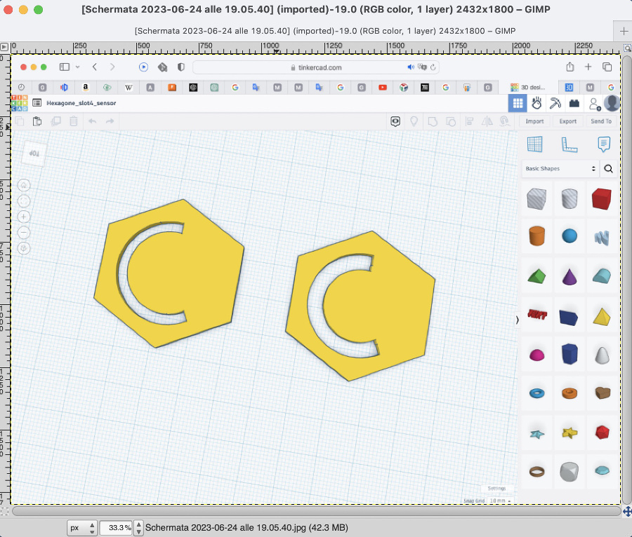
The image to be resized is displayed in the main window:
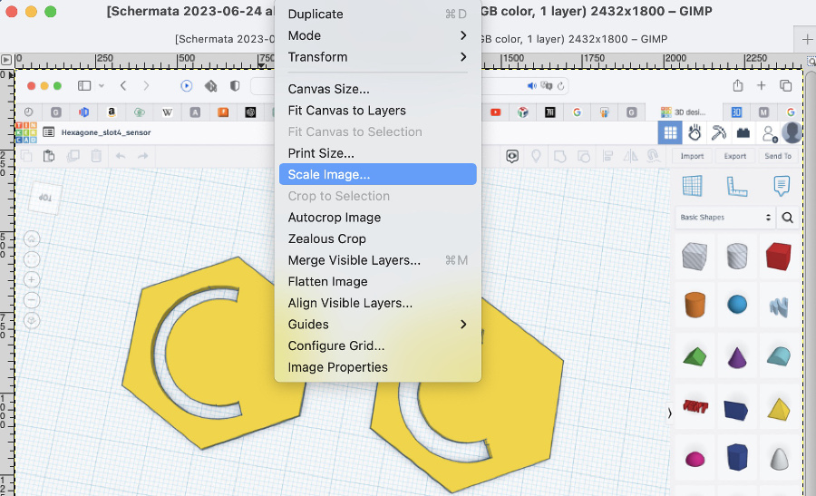
Go to menu "Image" and select "Scale image":
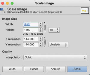
The current dimensions of the image are displayed (in Pixels)
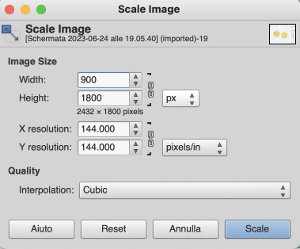
Change of the dimensions, putting 900 for the width of the image. The height is automatically recalculated since both fields height and width are linked (see the chain symbol).
Note: after testing different values, I have adopted 900 px as the most suitable dimension for my images.
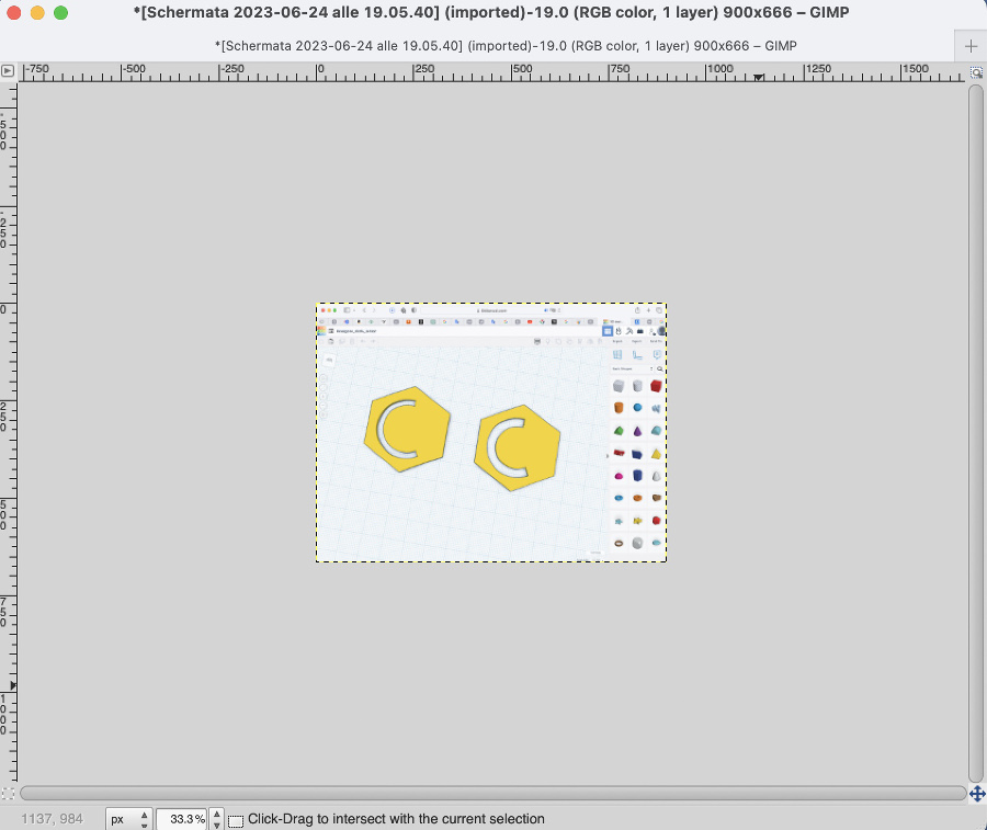
Click on "scale".Overview of the image after resizing:
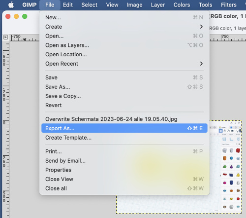
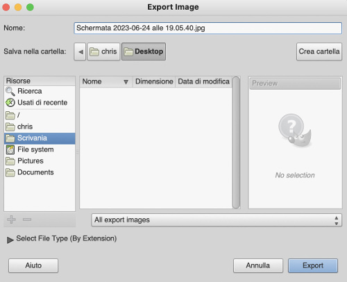
Go to menu "File" and select "Export as"
Click on export:
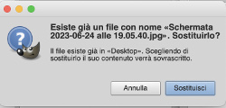
A Pop-up window informs you that there's already a file with the same name and asks confirmation to "Substitute" or "Cancel"
Click on "Substitute":
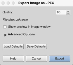
Select the Quality level (% of compression) of the .jpg. In general I keep the value recommended by GIMP:
Click on "Export" and resized file in .jpg format is saved.
Softwares for 3D modelling:
For the needs of the project, I have decided to experiment Tinkercad that is an online CAD system. Friends recommended me to try this tool and said it's very user-friendly.
Tinkercad is a web-based CAD software developed by Autodesk that does not require any installation. It has clearly been created and designed for beginners, students who are new to CAD and 3D modeling.
The Tinkercad interface is very simple and intuitive tools, making it easy to create and design 3D models without requiring extensive technical knowledge or experience.
Outlook of the main interface:
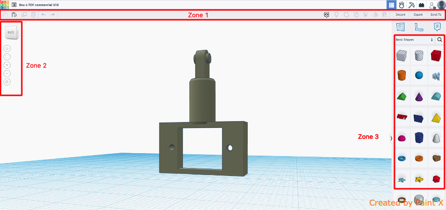
Zone 1: top toolbar, with more general tools like “Copy”, “Paste”, and “Delete” on the left and design operations like “Group” and “Align” on the right.
Zone 2: navigation tools for basic orientation like zoom in and out. Note that these specific tools can also be used via mouse wheel.
Zone 3: shape Panel, containing all building blocks for designing, including basic shapes like cubes, spheres, and text.
Tinkercad, offers the possibility for users to create 3D models by manipulating basic geometric shapes, such as cubes, spheres, cylinders, and more.
As per screenshots below, tinkercad offers much more options that the simple geometric shapes and different libraries are available: creatures, vehicles, structures, hradware, electronics...
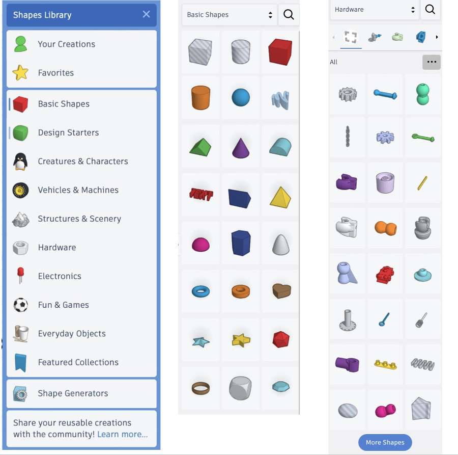
These shapes can be resized, rotated, and combined to form more complex objects. Tinkercad also offers features like text, letters, numbers, and pre-designed shapes to enhance the design process.
One of the reasons I wanted to test Tinkercad is because of its ability to create quickly models for 3D printing. This turned out to be a key asset and an accelerator in the prototyping phases of my final project.
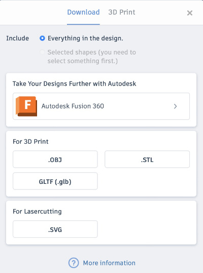
Tinkercad offers nice exporting options like STL format that which is widely used in 3D printing. Other export format like .OBJ and .GLTF are supported for 3D printing
Interesting to mention that .SVG format is also support towards Viny cutter world.
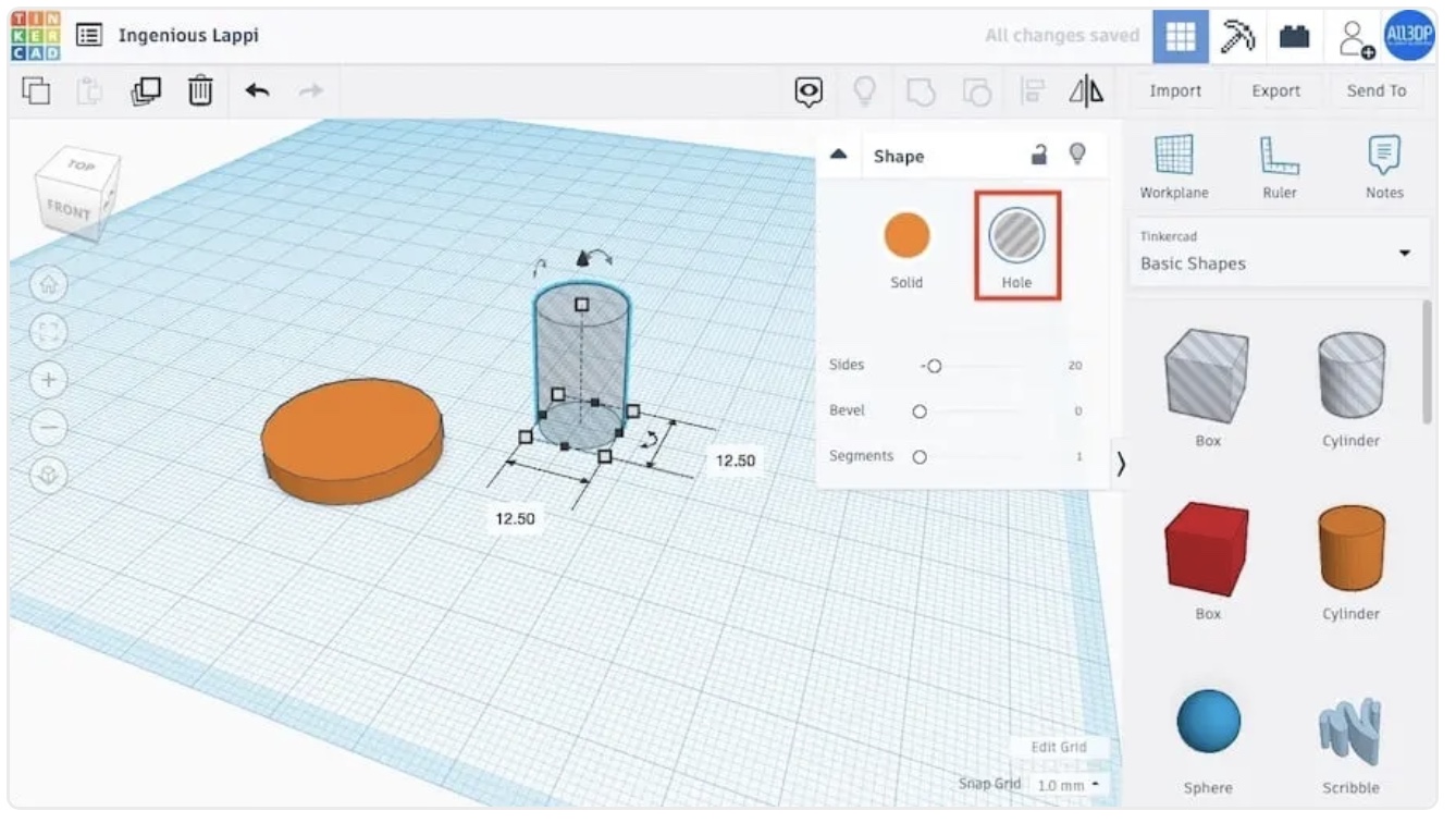
Boolean Operations & Holes:
Tinkercad operates on the principle of Boolean design, which allows the subtraction of objects to create empty areas and the addition of objects to form new shapes.
Example of one of my first test of subtraction operation to create a circular hole in our ring:
,
Alignment operations:
The alignment function is available in the top toolbar:

How to use the alignment tool:
Leveraging tinkercad for my Final project:
In the first iterations of the construction of the final project, tinkercad offered me a nice toolkit to quickly produce models to be 3D printed, assembled and tested.
Examples of elements created with this tool:
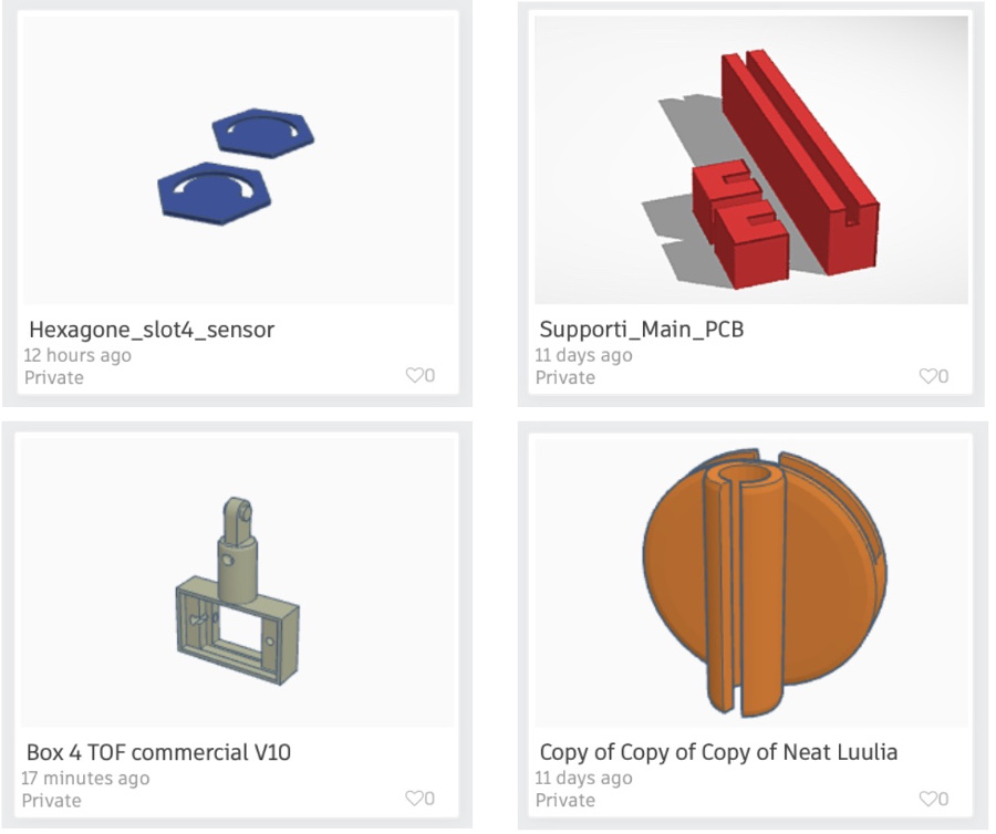
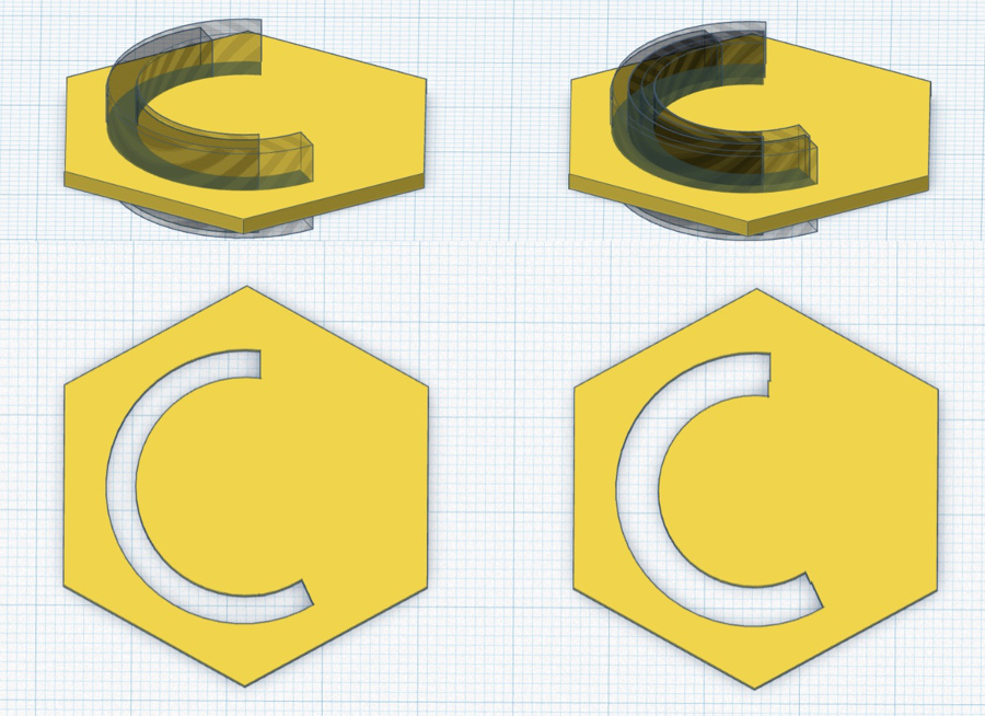
On the upper line, on the left some hexagon used in the central part of the rotation mechanism below the origami. We can see the notch created for the passage of the wires coming from the light sensor. Different attempts were needed to arrive at the correct width of this notch and tinkercad has been very helpful in these iterations.
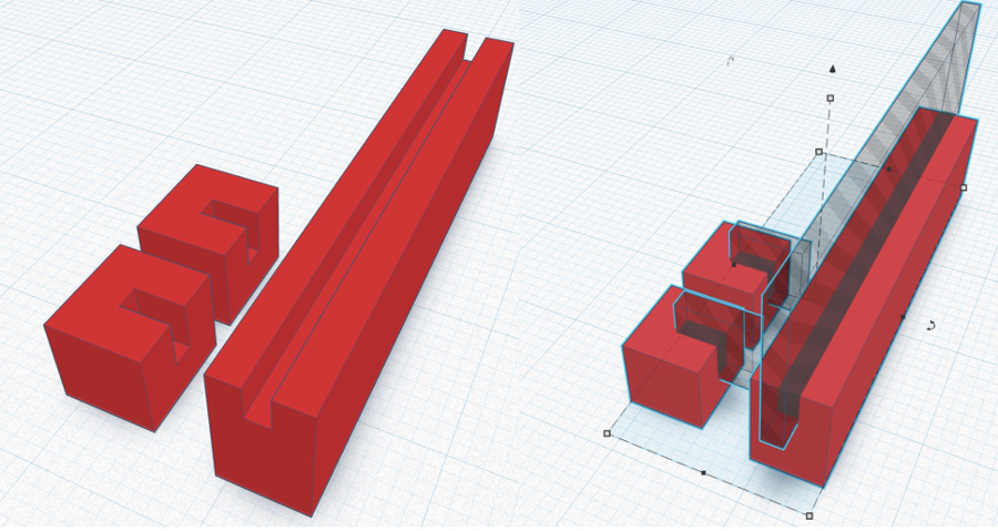
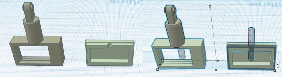
On the upper line on the right side, three simple elements created to support the main PCB and fix it in the central plexiglass box:
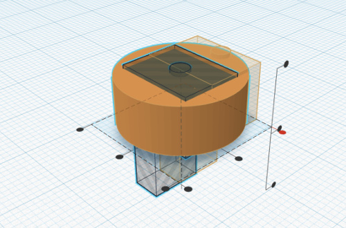
Overview in tinkercad of the support and enclosure designed for the TOF sensor:
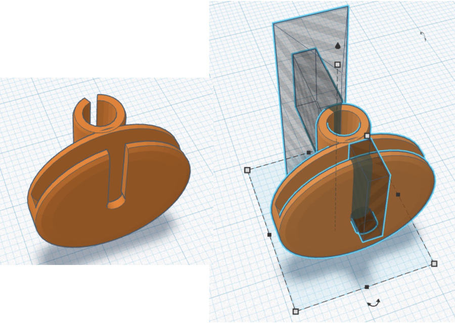
View of the component "ball joint and fixing system" designed to enable rotation and fixing of the tubes of the structure
Video editing SW:
I thought it would be intersting for the benefit of our community to share my experience on a tool that I have discovered, installaed and used to make the 1 minute clip of my final project.
The name of this tool is CapCut and it's a very seimple but powerful tool in the area of stickers and animations.
CapCut offers different option: video editing online, mobile app video editing and installation package for Mac OS.
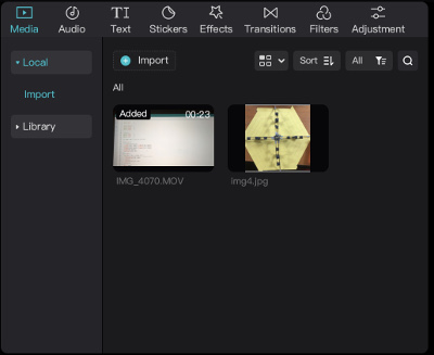
MAC OS version, overview of the main page:
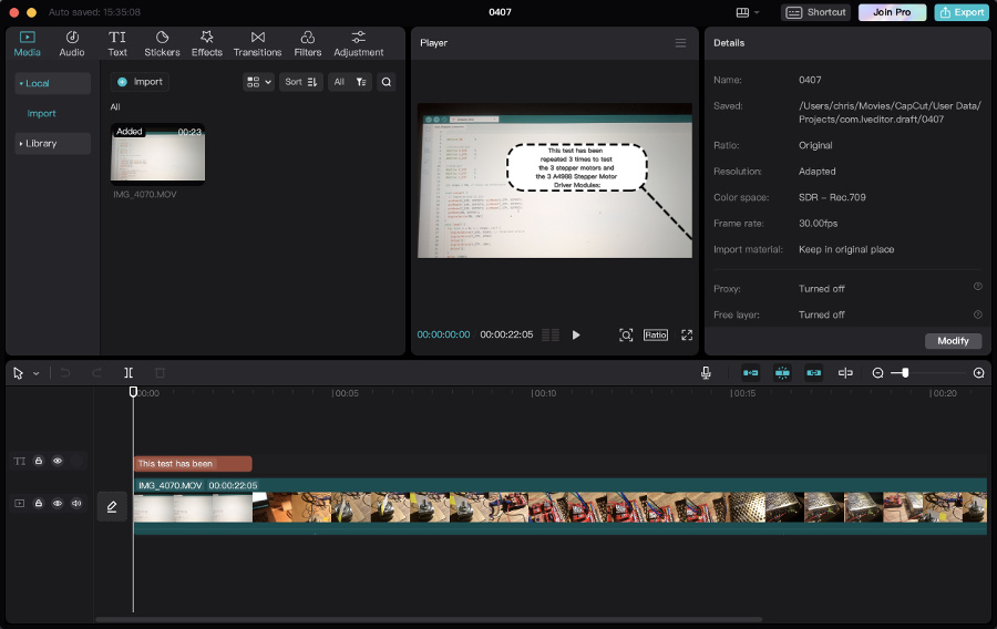
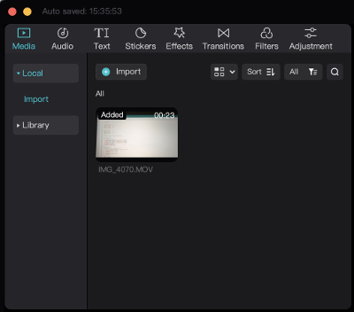
Media area: list of the contents currently imported and available in the library:
Right after import of a picure of my final project (Origami and mechanical structure):
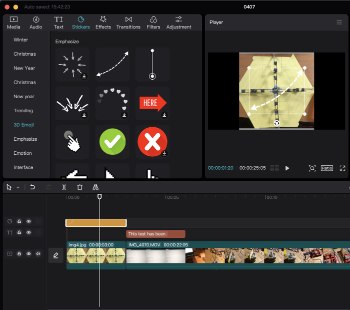
Drag and drop of the piture into the timeline.
Click on the "Stickers" icon in the main menu bar (on the upper part)
Selection of the curved and dashed arrow (appropriate to visually explain how the Origami unfolds).
Drag and drop of the sticker on the timeline in corespondance to the image.
On the uppper / left part, possibility to position and redimension the sticker.
Duration of appearance can be adjusted directed on in the timeline area.
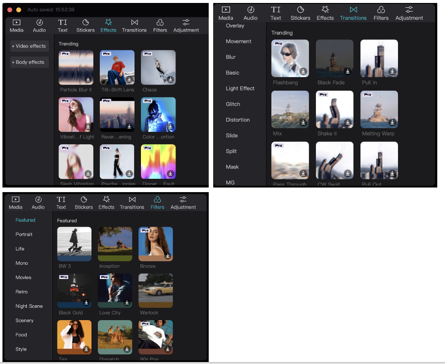
Overview of the "effects", "transitions" and "filters" offered by the tool: