


Below is Animation Combines All for CAD
Individual Assignment.
Design and produce something with a digital fabrication process (incorporating computer-aided design and manufacturing) not covered in another assignment, documenting the requirements that your assignment meets, and including everything necessary to reproduce it. Possibilities include (but are not limited to):
In this week 15 of Wildcard for me I have called it the week of brainstorming and reasoning week because like an open space for me to think what i have to do,It was quite challenging for me to think what I can do in this week of wildcard.
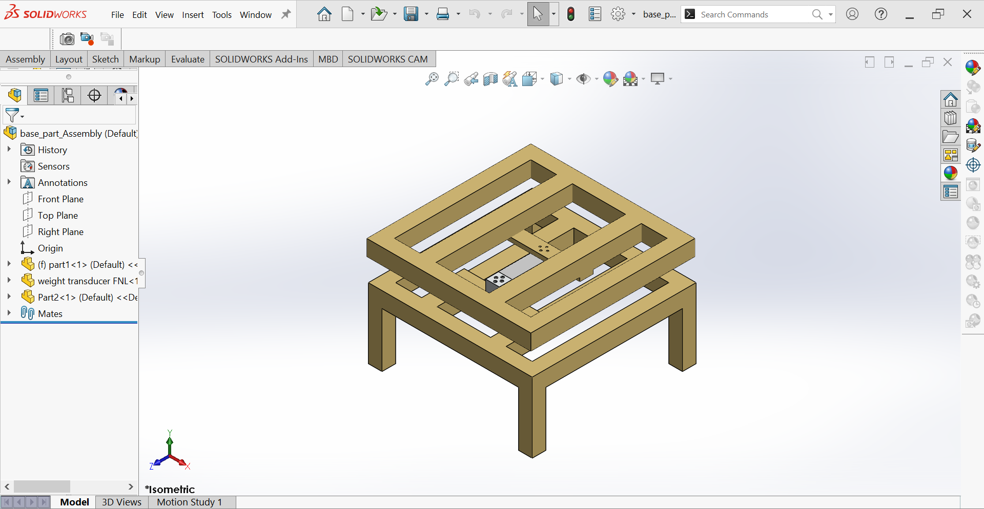
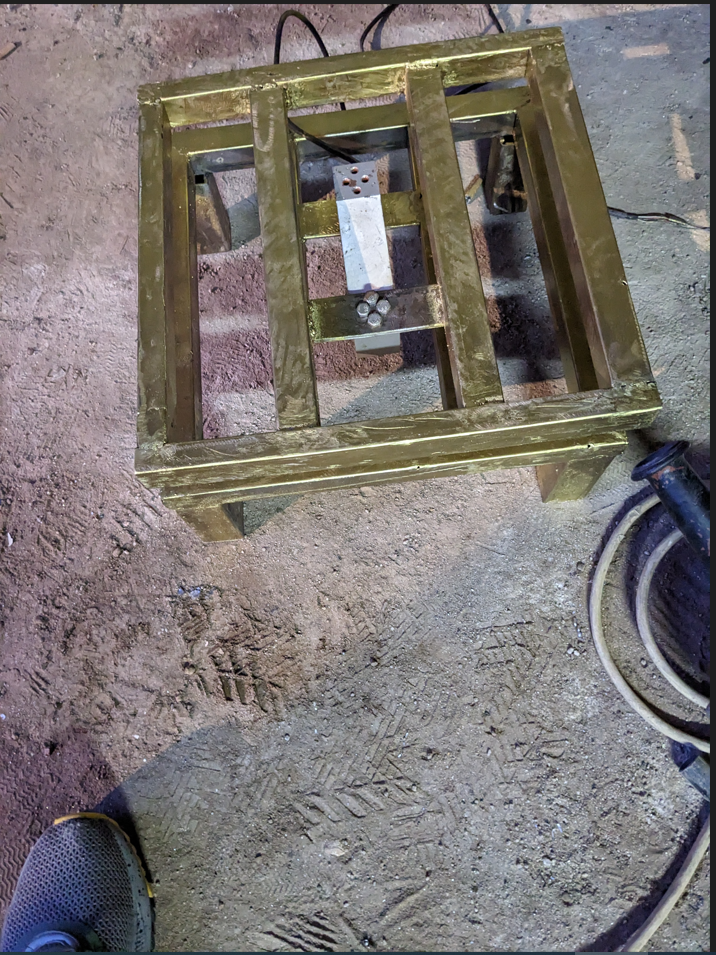
After taking a moment of brainstorming I decided to use Welding Technology to design my Base Part which I used later in the Final Project.,Then for this I used Arc Welding To implement it.
Firstly, Welding: Welding:is a fabrication process that joins materials, usually metals or thermoplastics, by using high heat to melt the parts together and allowing them to cool, causing fusion.
There are different types of Welding which are:Gas Metal Arc Welding (GMAW/MIG), Gas Tungsten Arc Welding (GTAW/TIG), Shielded Metal Arc Welding (SMAW), and Flux Cored Arc Welding (FCAW), for more info you can visit Here
For Me I have used Shielded Metal Arc Welding (SMAW):is a fusion welding process that uses a consumable, flux-coated electrode to create an arc between the electrode and the work piece.
There are main Components I used in Shieded Metal Arc Welding.
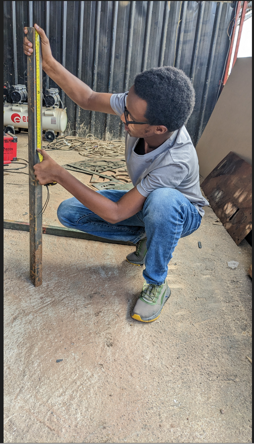
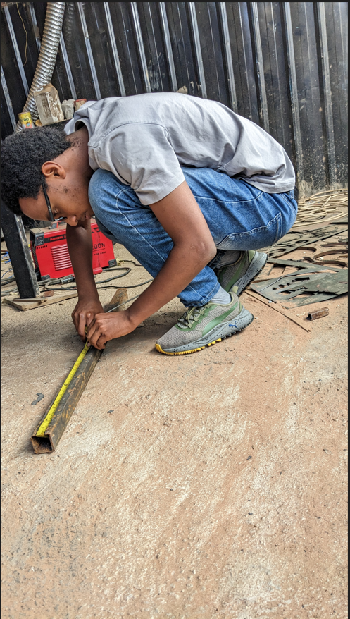
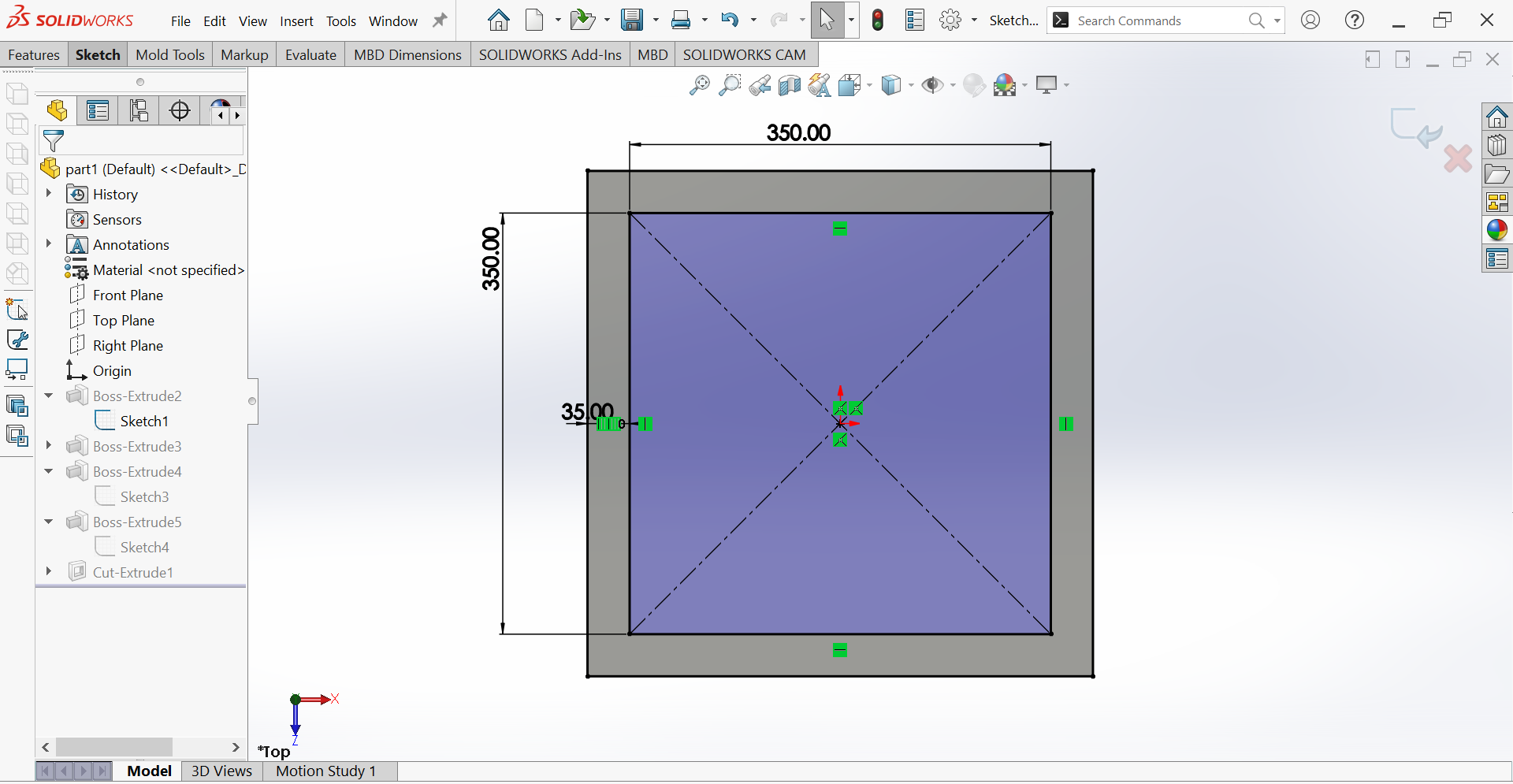
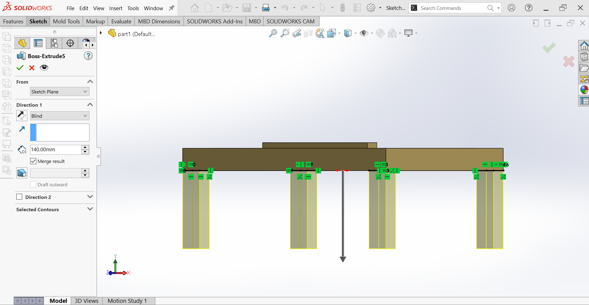
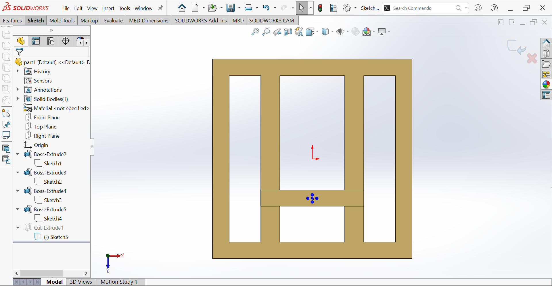
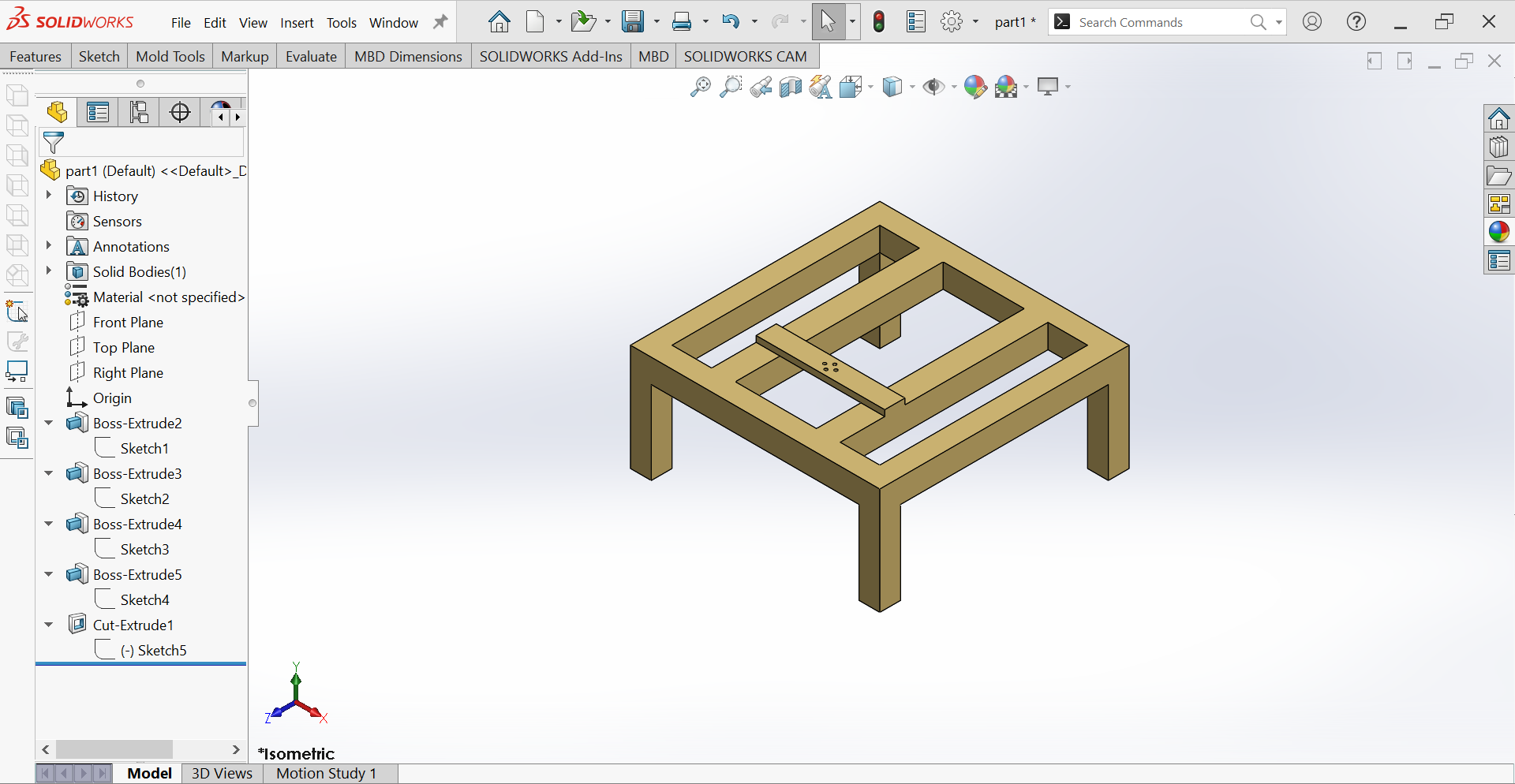
Firstly I made Computer Aided Design by Using Solidworks and Then I welded by using Desired Dimensions.
Below Are the steps of how I did in CAD(Computer Aided Design).
Below is Animation Combines All for CAD
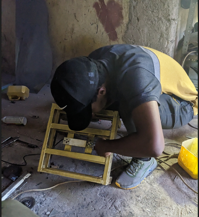
I have used almost all the components used in Metal Welding to design the Base part of the BMI Machine.

Let me go in the details how I reached to the final product in Welding.