Week 4:Embedded Programming
Assignment activities
1.Individual Assignment.
.browse through the data sheet for your microcontroller
.program a microcontroller development board to interact and communicate.
2.Group Assignment.
.compare the performance and development workflows for other architectures
Here you can access the group assignment in details here
Embedded Programming: is a computer system—a combination of a computer processor, computer memory, and input/output peripheral devices—that has a dedicated function within a larger mechanical or electronic system.It is embedded as part of a complete device often including electrical or electronic hardware and mechanical part, Because an embedded system typically controls physical operations of the machine that it is embedded within, it often has real-time computing here
I was eager to start this week because of embedded programmming though it was quite difficult for me because was my first time to use electronic softwares and devices but luckily Arduino was quite similar to C and C++ programming language and I was used in c and c++, I runned basics faster and I wish to make progress on this new journey of electronics , so that at the end i combine mechanical and electronics since they work together.
1.Individual Assignment.
During group review our colleagues who studied electronics have played big role in giving us the whole picture of the electronics starting with the simple circuit until the general idea of Arduino, this was nice background for us to go ahead and make the research to improove my skills regarding eectronics.
I.Browse Through The Data Sheet For Your microcontroller
It was really challenging to start reading datasheet without knowing the key features of the Microcontroller,However on Saturday during Global Open Sesseion I got the whole concept of Microcontroller and I managed to get highlight what I read in datasheet as in the key features.
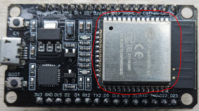
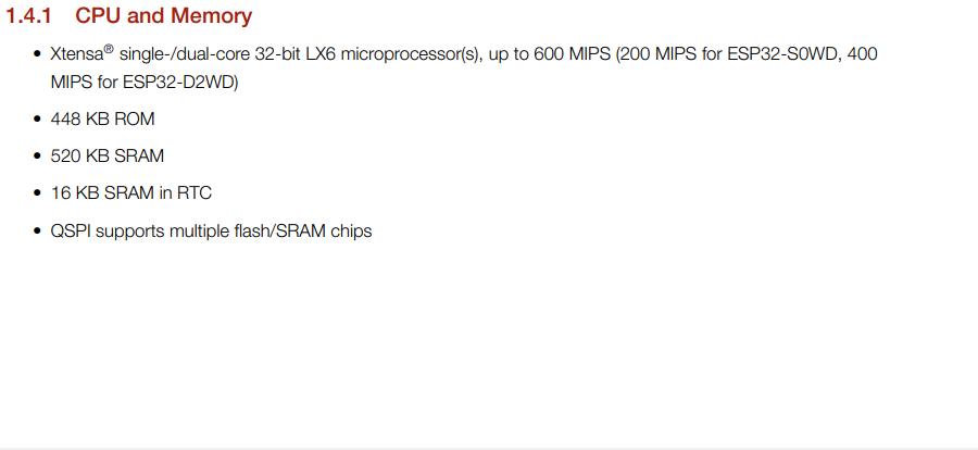
In my first implementation I used ESP32 as my Microcontroller,and the next step was to read datasheet of ESP32,Basically he ESP32 is a microcontroller designed by Espressif Systems, which is used for a wide range of applications including IoT, automation, and robotics.
datasheet is basically A datasheet for a microcontroller (MCU) provides detailed technical information about the device, including its electrical and physical characteristics, functional description, pin assignments, memory organization, peripheral interfaces, power consumption, and programming information.
Specifically since I used ESP32 as my Microcontroller, and it's description is Below;
-
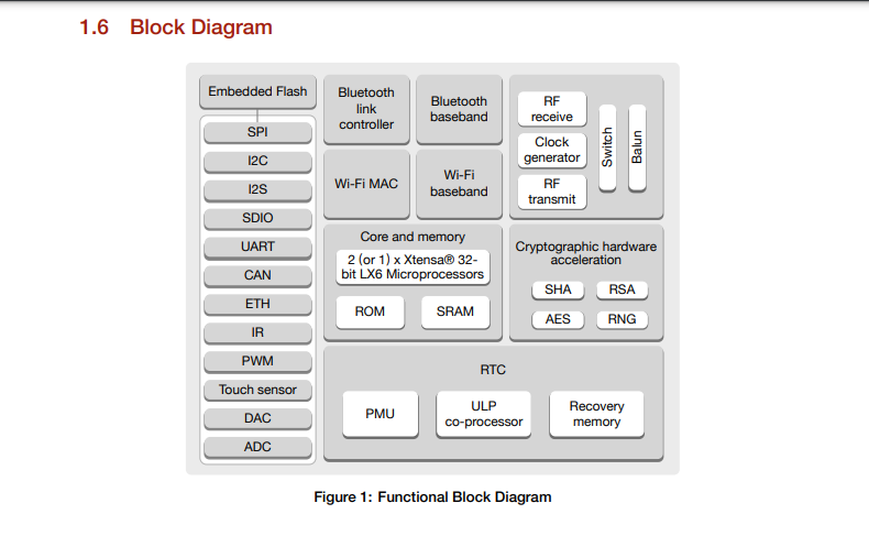
ESP32 Architecture is composed of the general illustration of the ESP32 MCU and it's internal components.
-
ESP Clock Speed is used in determining the number of cycles your CPU executes per second, and its unit is hertz(cycles/second).

Regarding the Memories, it is composed of 5 types of memories and are described below;
-
Program Memory (Flash): This is non-volatile memory used to store the firmware or program that runs on the ESP32. It is also known as Flash memory and has a capacity of up to 16 MB.
-
Data Memory (RAM): This is volatile memory used for temporary storage of data during program execution. It is also known as Random Access Memory (RAM) and has a capacity of up to 520 KB.
-
Non-volatile Memory (NVS): This is a special type of memory used to store persistent data that needs to be retained even when the power is off. It is used to store configuration data, such as Wi-Fi credentials, and has a capacity of up to 4 KB.
- External Memory: The ESP32 also supports external memory, such as SPI Flash or SD cards, which can be used to expand the storage capacity of the module
-
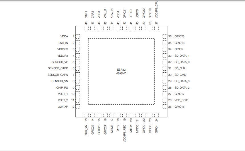
Pins of the ESP32 Microcontroller,The ESP32 microcontroller has a total of 48 pins, which are used for various functions, including input/output (I/O), power, communication, and other purposes. These pins are divided into several groups, each with a specific function. Here is a summary of the different pin groups and their functions:
GPIO Pins:There are a total of 34 GPIO (General Purpose Input/Output) pins on the ESP32, which can be used for digital input and output, PWM, and other functions Analog Pins: There are 18 ADC (Analog-to-Digital Converter) pins on the ESP32, which can be used for analog input.
Power Pins:There are two power pins on the ESP32, labeled VCC and GND, which provide power to the module.
Communication Pins:The ESP32 supports several communication protocols, including I2C, SPI, UART, and CAN. There are multiple pins dedicated to each of these protocols.
other Pins:The ESP32 also has a number of pins dedicated to other functions, such as the boot mode selection pins, the EN (enable) pin, and the USB pins for programming and debugging.
Pin Layout below
Regarding the communication protocol,The ESP32 microcontroller supports several communication protocols that enable it to communicate with other devices or systems. Some of the most common communication protocols supported by the ESP32 include:
-
Wi-Fi: The ESP32 has built-in support for Wi-Fi, which allows it to connect to wireless networks and communicate with other devices or systems over the internet.
- Bluetooth: The ESP32 also supports Bluetooth, which allows it to communicate with other Bluetooth devices, such as smartphones, tablets, or other IoT devices.
- Serial Peripheral Interface (SPI): The ESP32 has hardware support for SPI, which is a synchronous serial communication protocol commonly used for communication between microcontrollers and other digital devices.
- Inter-Integrated Circuit (I2C): The ESP32 also has hardware support for I2C, which is a two-wire communication protocol used for low-speed communication between microcontrollers and other digital devices.
- Universal Asynchronous Receiver-Transmitter (UART): The ESP32 also has hardware support for UART, which is a popular asynchronous serial communication protocol used for communication between microcontrollers and other devices, such as sensors, GPS modules, or other microcontrollers.
- AN (Controller Area Network): The ESP32 also supports the CAN protocol, which is a popular communication protocol used in automotive and industrial applications for communication between microcontrollers and other devices over long distances.
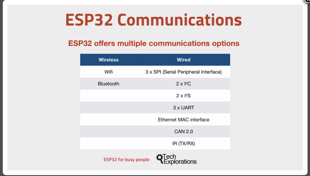
The ESP32 also has support for other communication protocols, such as Ethernet and USB, through external interfaces or modules. By supporting a wide range of communication protocols, the ESP32 is a versatile microcontroller that can be used in a variety of applications that require communication with other devices or systems.
The ESP32 microcontroller requires a power supply to function properly.The power supply can be provided through several different methods, depending on the specific application and requirements. Here are some common methods of powering an ESP32:
-
USB Power:The ESP32 can be powered through a USB port, using a USB cable connected to a power source such as a computer, USB wall adapter, or USB power bank.
- Battery Power:The ESP32 can also be powered using a battery, either through a battery holder or by connecting the battery directly to the VCC and GND pins on the ESP32 board. The battery voltage should be within the recommended range for the ESP32, which is typically between 3.3V and 5V.
- External Power Supply:The ESP32 can also be powered using an external power supply, such as a wall adapter or DC power supply. The voltage and current rating of the power supply should be within the recommended range for the ESP32 board being used.
- Solar Power: The ESP32 can also be powered using solar panels or other renewable energy sources, by connecting the panels to a battery or external power supply.
It is important to note that the ESP32 can consume a significant amount of power, depending on the specific application and usage. To optimize power consumption, the ESP32 includes several power-saving features, such as deep sleep mode and low-power modes for individual components. These features can help extend the battery life or reduce the power consumption of the ESP32 in certain applications.
II.program a microcontroller development board to interact and communicate.
It was almost 2 years to hear Arduiono software which can be used in control of the boards which can be used like designing the Robot and other automated devices,I was really to see my codes running in Arduino and LED lighting say WOOW it runs.
We started on basics of electronics and we proceeded with Microprocessor and Microcontroller ,the major difference I will always was that on the Microcontroller its CPU in single chip(all memories are internally equiped) and Microprocessor its CPU server and several support memories(all Memories are externally equiped)
and also types of the memory like :flash memory(for programs),SRAM(For currently working softwares,temporary working),EEPROM(for keeping files permanently)
We review the syntax and some basic keywards which are used in Arduino, because in the electronic softwares I prefered to use Arduino since it's the one I heard before and in our country its the commonly used software in electronics.
The next step was to download Arduino setup for and it firstly become challenging , because I download the running app and once i was updated the drivers failed to be installed in my pc,
Below are the steps I followed while i was installing and starting Arduino software.
-
I go to my browser (Google Chrome) and type "Arduino download", I downloaded setup
Arduino IDE 1.8.19 (Windows zip file) through here's link, I downloaded this zip file so that i can get the whole software setup with it's drivers.
-
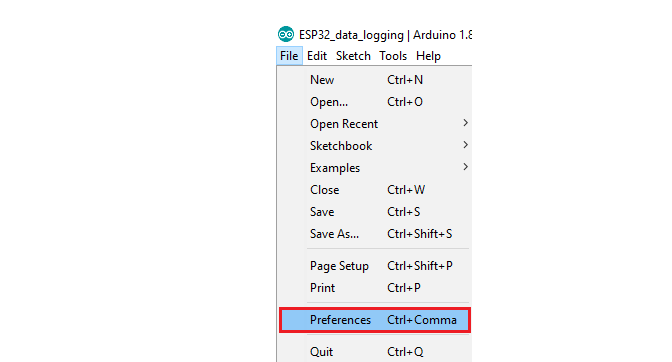
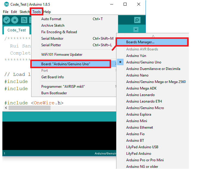
Because Arduino does not have the board i have (ESP 32 Devkit) in it's built in boards so I was having to add it in the Arduino IDE to get it's access,below are the steps
-
In your Arduino IDE, go to File> Preferences
-
Next step is go to google and type"esp-wroom-32 arduino board manager",or use this link here:
You will copy this code
https://raw.githubusercontent.com/espressif/arduino-esp32/gh-pages/package_esp32_index.json

Then, click the “OK” button:
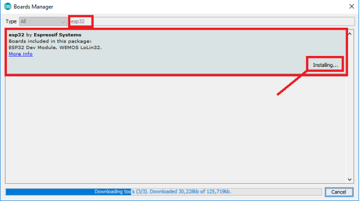
Open the Boards Manager. Go to Tools > Board > Boards Manager
-
Search for ESP32 and press install button for the “ESP32 by Espressif Systems:
-
Thats it,It should be installed after a few seconds, and when I come back to my boards I find it in those.

After finishing adding the ESP32 board in the Arduino IDE,I proceeded programming and linking the devices with their output.
Output Microcontroller development board to interact With Arduino
The first step I did is the output, I programmed codes using Arduiono Language with ESP32 Microcontroller, Below are steps I passed while blinking the LED
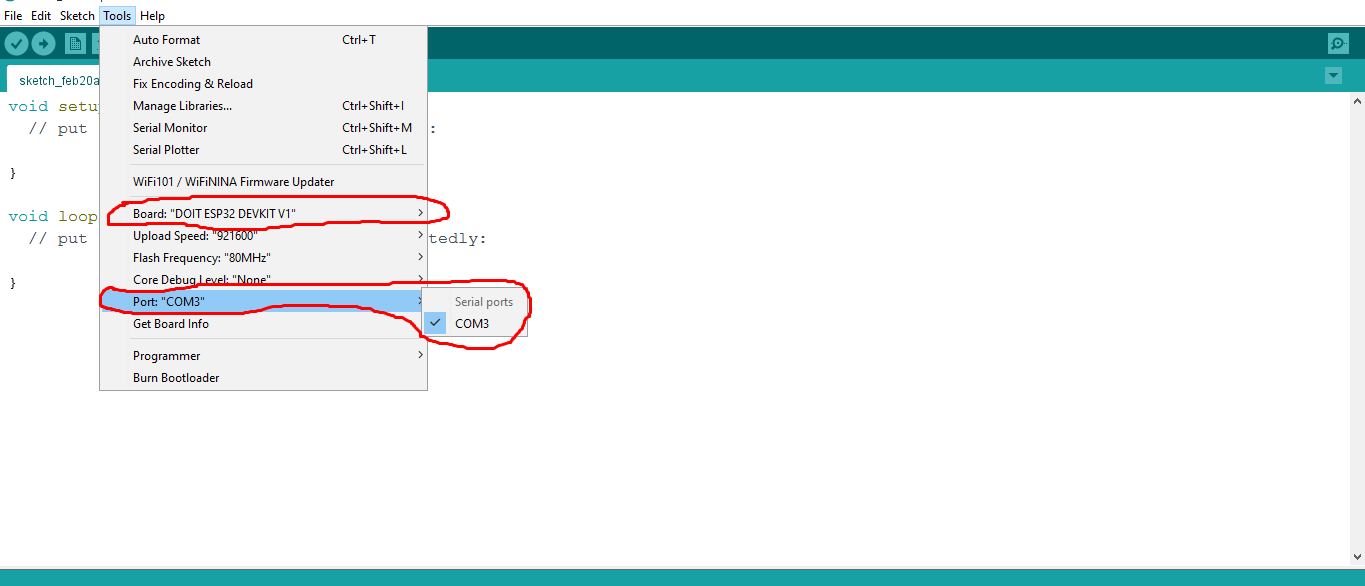
Creating the new document, and select the port and board I am using while programming , my board is ESP 32 DEVKIT V1 and the port is com3.
After the configuration of port and board, the Source Code i Programmed for displaying the blinking Leds are below;
int red= 23;
int red1= 22;
int green1= 21;
int yellow= 19;
int yellow1= 18;
int white= 5;
int white1=15;
void setup() {
pinMode(red,OUTPUT);
pinMode(red1,OUTPUT);
pinMode(green1,OUTPUT);
pinMode(yellow,OUTPUT);
pinMode(yellow1,OUTPUT);
pinMode(white,OUTPUT);
pinMode(white1,OUTPUT);
}
void loop() {
digitalWrite(red,HIGH);
delay(1500);
digitalWrite(red,LOW);
digitalWrite(red1,HIGH);
delay(1500);
digitalWrite(red1,LOW);
digitalWrite(green1,HIGH);
delay(1500);
digitalWrite(green1,LOW);
digitalWrite(yellow,HIGH);
delay(1500);
digitalWrite(yellow,LOW);
digitalWrite(yellow1,HIGH);
delay(1500);
digitalWrite(yellow1,LOW);
digitalWrite(white,HIGH);
delay(1500);
digitalWrite(white,LOW);
digitalWrite(white1,HIGH);
delay(1500);
digitalWrite(white1,LOW);
  }
For the final output LED blinking the photo is below.

And this is video when it was working , Woow it's really amazing, This was my desire to use Arduino and program running project.
The Second step I did is to interact by input command,I programmed codes using Arduiono Language with ESP32 Microcontroller, Below are steps I passed while blinking one LED by using button.
Creating new document as I did for output and then configure the board(ESP 32 DEVKIT V1) and port(COM3)
The next is to communicate Remotely i used bluetooth Mode, and below are the steps I used to reach this connection.
The next step is to modify the syntax and blink the LED remotely by bluetooth mode, below are the codes

