Week 4: Embedded Programming
Embedded Programming
| MCU Architecture | Performance | Development Workflows |
|---|---|---|
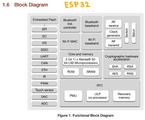
| ESP32 | Strong dual-core CPU with 520 KB SRAM, Wi-Fi, and Bluetooth connectivity, operating at up to 240 MHz. Additionally, it has integrated hardware acceleration for digital signal processing, cryptographic methods, and more. | Development can be done using the Arduino IDE or the ESP-IDF (Espressif IoT Development Framework). The ESP-IDF provides low-level access to the hardware, allowing for fine-grained control over the MCU. The ESP32 also has a large and active community, with plenty of tutorials, examples, and libraries available. |
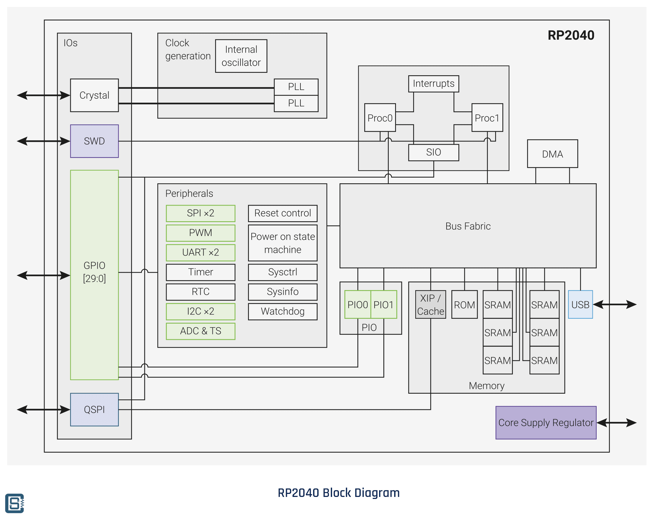
| RP2040 | Powerful dual-core processor, clocked at up to 133 MHz, with 264 KB of on-chip RAM and support for up to 16 MB of external flash. It also has programmable IO, allowing for complex interfacing with external devices. | Development can be done using the C/C++ programming language and the official RP2040 SDK, which provides access to the hardware at a low level. The RP2040 also has a growing community, with a variety of development boards and accessories available. |
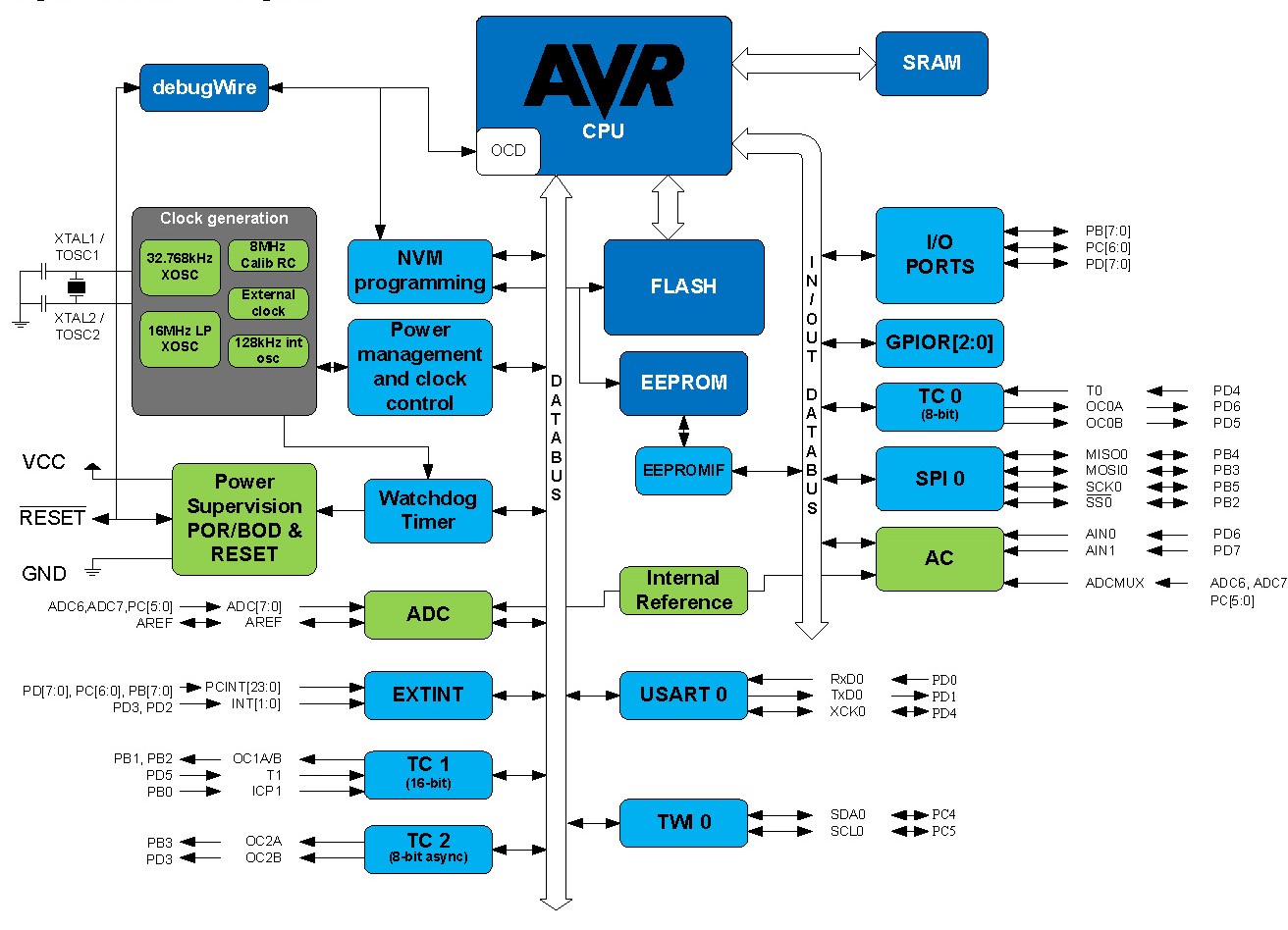
| ATmega328P | Relatively low-powered, with a 20 MHz clock speed and only 2 KB of RAM. It is often used in low-power or low-cost applications, such as simple sensors or small IoT devices. | Development can be done using the Arduino IDE, which provides a simplified and beginner-friendly development environment. The ATmega328P is also well-documented, with plenty of tutorials and examples available online. |
 RP2040 Block Diagrams
 ATmega328P Block Diagrams
 Useful Links
- 1.ESP32:ESP32 Datasheet
- 2. RP2040:RP2040 Datasheet
- 3. ATmega328P: ATmega328P Datasheet
What is Embedded Programing? Embedded programming is the process of writing software that is specifically designed to control the operation of a computer system embedded within a larger device or machine. This type of programming involves writing code that is optimized for the hardware and often requires a deep understanding of the system's architecture. Here
What is Arduino programming language?
Arduino programming language is a simplified version of C/C++, which is used to write code for Arduino microcontrollers. Arduino is an open-source electronics platform that provides a flexible and easy-to-use hardware and software environment for creating interactive projects.Here is a simple example of the Arduino programming language code for blinking an LED connected to pin 13:
                // Set pin 13 as an output
void setup() {
  pinMode(13, OUTPUT);
}

// Blink the LED on pin 13
void loop() {
  digitalWrite(13, HIGH);
  delay(1000);
  digitalWrite(13, LOW);
  delay(1000);
}
In this example, the setup() function is used to configure the pin 13 as an output, and the loop() function is used to blink the LED on pin 13. The digitalWrite() function is used to turn the LED on and off, and the delay() function is used to pause the code for a specified amount of time. Overall, the Arduino programming language is easy to learn and use, making it popular for hobbyists, students, and professionals who want to prototype and develop microcontroller-based projects.
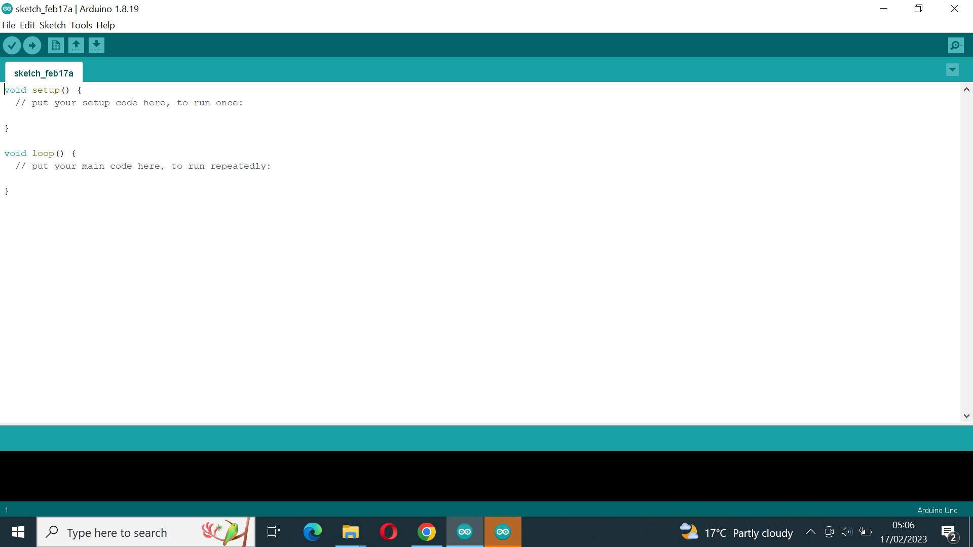
A. The first task was to download and install Arduino Software
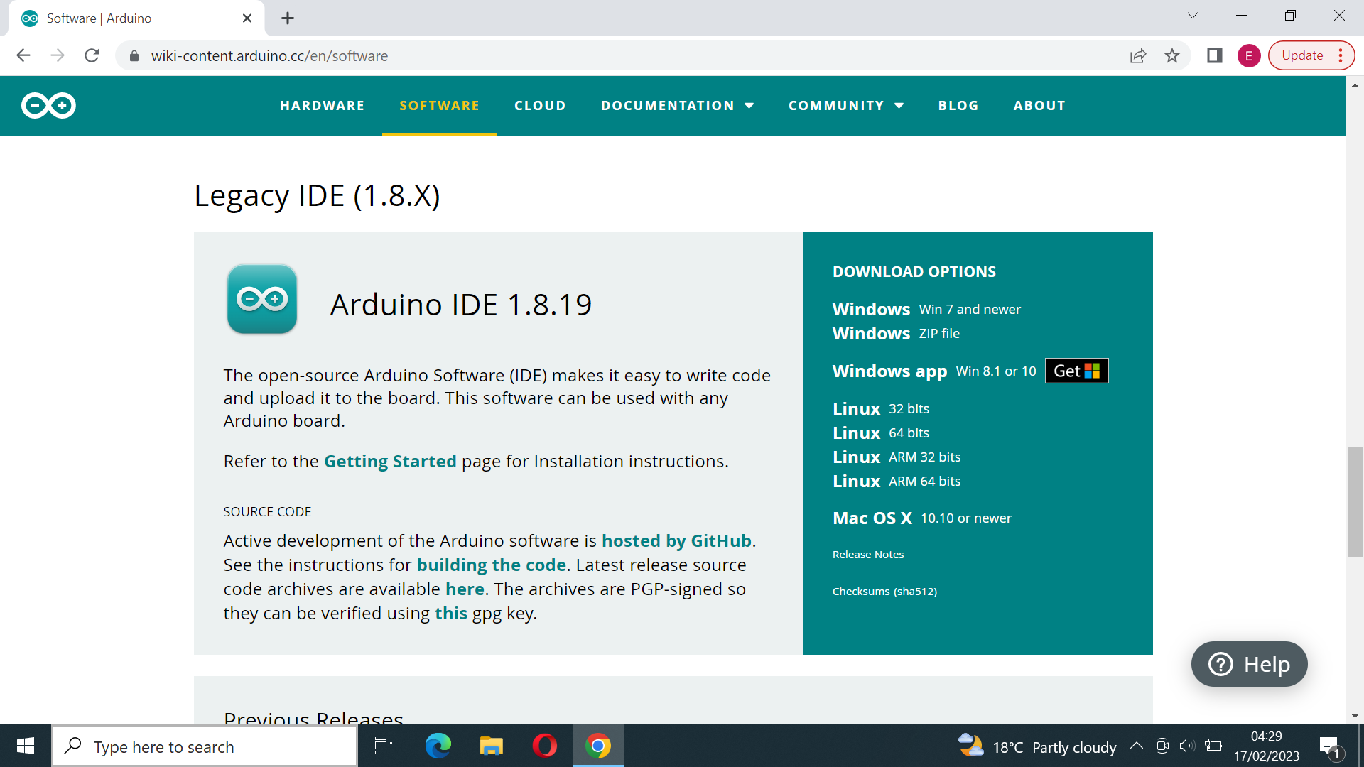
Because we will use Arduino ESP32 Board we will need to install ESP32 Add-on in Arduino IDE
1st step Open the Arduino IDE and click on "File" in the top left corner. From the "File" menu, click on "Preferences".
.png)
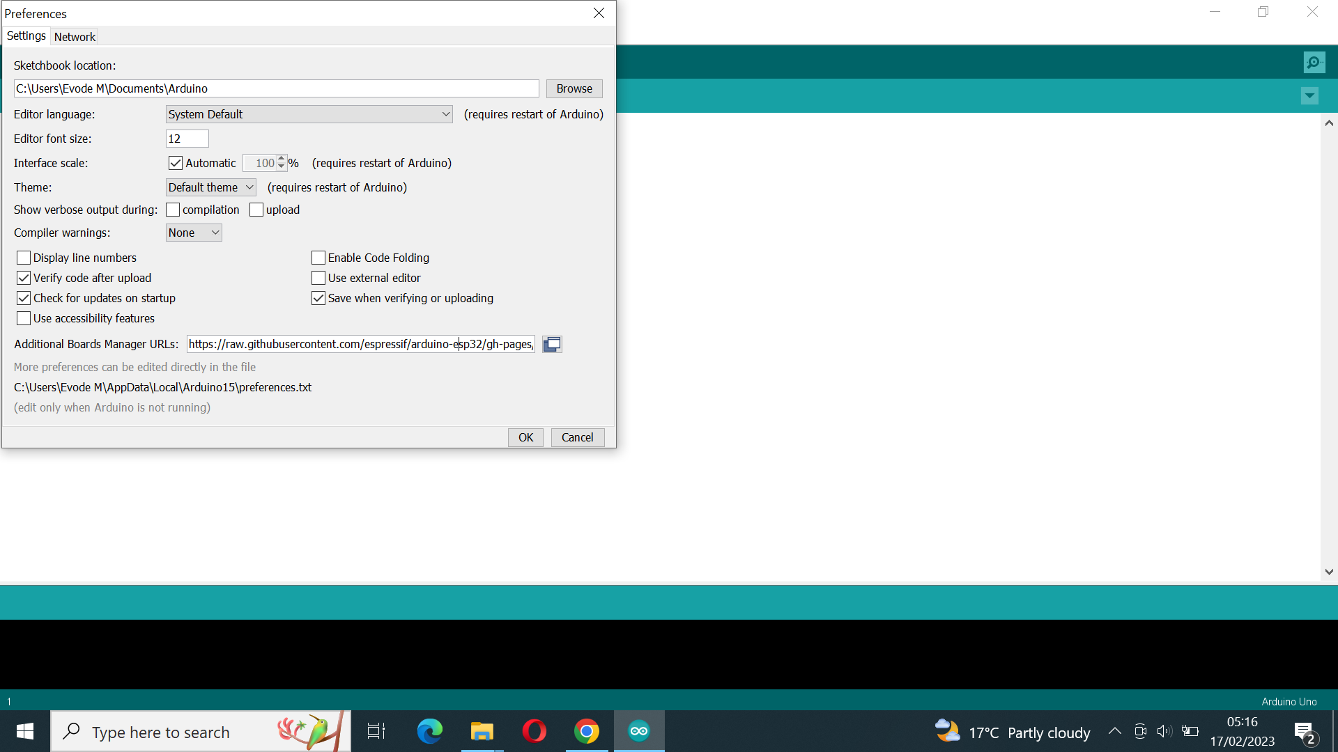
2nd Step In the "Preferences" window, look for the "Additional Boards Manager URLs" field and click on the button on the right to edit it. In the pop-up window, add the following URL: https://raw.githubusercontent.com/espressif/arduino-esp32/gh-pages/package_esp32_index.json and click "OK".
3rd Step Go back to the Arduino IDE's main window and click on "Tools" in the top left corner. From the "Tools" menu, click on "Board" and then "Boards Manager".
.png)
4th Step Click on the "Install" button and wait for the installation to complete
.png)
5th Step We connect Computer and DO IT ESP#@ DEV KIT but unfortunately its drivers not updated, we update these drivers as shown on following screen shots
.png)
.png)
6th Step Then the drivers was updated
.png)
Datasheets typically include a variety of information, including::
- Product identification information, such as the product name, part number, and manufacturer
- Physical and electrical specifications, including dimensions, weight, power consumption, and operating conditions
- Pinouts and signal descriptions for any connectors or interfaces
- Functional block diagrams and descriptions of the product's features and capabilities
- Electrical and timing characteristics, including input and output voltage and current, timing diagrams, and signal levels
- Application notes, including recommended usage guidelines, performance data, and other relevant information
In this assignment we are going to use Microcontroller ESP32
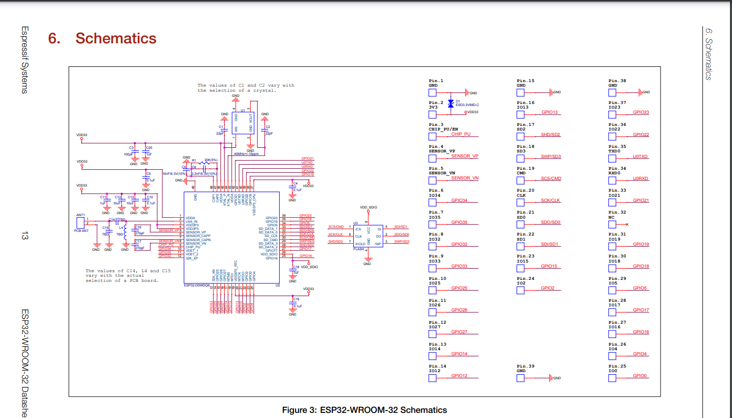
What is ESP 32? The ESP32 is a popular microcontroller that is widely used in Internet of Things (IoT) and embedded systems applications. It is produced by Espressif Systems, a Chinese company that specializes in designing and manufacturing low-power wireless systems-on-chip (SoCs) and modules. For Reference Read esp32-wroom-32_datasheet Here
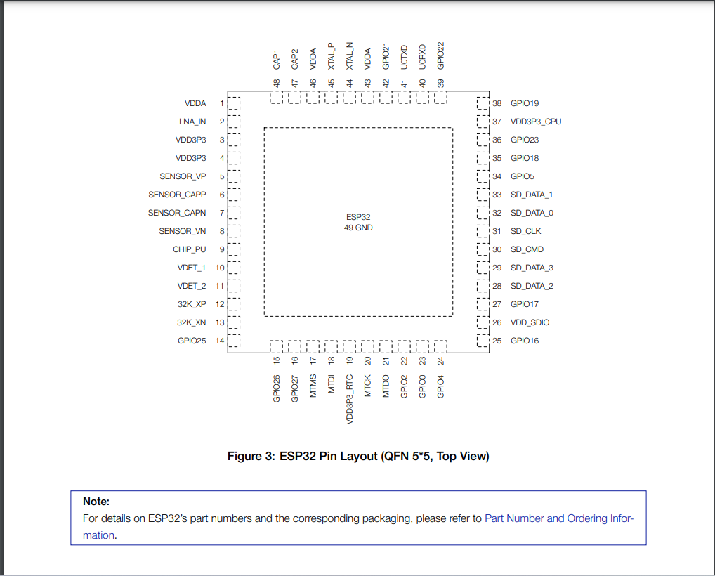
ESP32 Microcontroller with Pin descriptions
Here are some key specifications and features of the ESP32 microcontroller:
1.Architecture of ESP32
The ESP32 microcontroller is based on the Xtensa LX6 processor, which is a dual-core 32-bit microprocessor. It has two Tensilica LX6 CPU cores running at up to 240 MHz, and supports both 32-bit and 16-bit instructions. The ESP32 also has a range of communication interfaces, including UART, SPI, I2C, and Ethernet. Additionally, it has a built-in boot loader and supports over-the-air (OTA) updates, making it easy to update firmware remotely. The architecture of the ESP32 includes a range of power-saving features, such as sleep modes and low-power peripherals. This makes it well-suited for battery-powered applications, as well as other applications where power consumption is a concern. Overall, the architecture of the ESP32 microcontroller is designed to provide a high level of performance and functionality, while also being flexible and easy to use. This has made it a popular choice for a wide range of embedded systems and IoT applications.
2.Clock Speed of ESP32
The ESP32 microcontroller has a clock speed of up to 240 MHz. It is based on a dual-core Xtensa LX6 processor, which has two CPU cores that can run at different clock speeds. The default clock speed of the ESP32 is 80 MHz, but it can be overclocked to up to 240 MHz in some cases. The clock speed of the ESP32 can be configured through software, using the built-in clock control registers. This allows developers to adjust the clock speed to optimize performance and power consumption for their specific application. It's important to note that higher clock speeds can result in increased power consumption, so it's important to balance performance requirements with power constraints when configuring the clock speed of the ESP32.
3.CPU and Internal Memory
ESP32-D0WDQ6 contains two low-power Xtensa® 32-bit LX6 microprocessors. The internal memory includes:
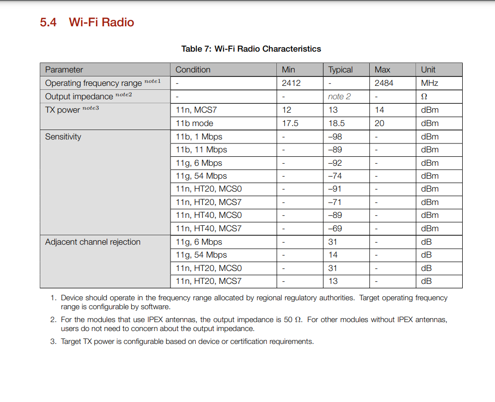
4.Wi-Fi Radio and Bluetooth
The Wi-Fi radio of the ESP32 microcontroller is a key feature that enables wireless communication with other devices. The ESP32's Wi-Fi radio supports the 802.11 b/g/n/e/i (2.4 GHz) standards, and can act as both a station and an access point.
Bluetooth
This Bluetooth module is a hardware component that enables the ESP32 to communicate wirelessly with other Bluetooth-enabled devices, such as smartphones, tablets, laptops, and other microcontrollers. The Bluetooth module on the ESP32 supports a wide range of Bluetooth profiles and protocols, including Bluetooth Classic, Bluetooth Low Energy (BLE), and Bluetooth Mesh. This allows the ESP32 to be used in a variety of applications that require wireless communication, such as home automation, industrial control systems, wearables, and more. The ESP32's Bluetooth module can be programmed and controlled using the ESP-IDF (Espressif IoT Development Framework), which provides a comprehensive set of libraries and tools for developing Bluetooth applications. This includes support for both the Classic and BLE versions of Bluetooth, as well as a range of Bluetooth profiles such as Serial Port Profile (SPP), Generic Attribute Profile (GATT), and more. Overall, the Bluetooth module in the ESP32 microcontroller is a powerful and versatile feature that adds significant value to the device and makes it an excellent choice for a wide range of IoT and embedded applications.5.Operating voltage/Power supply
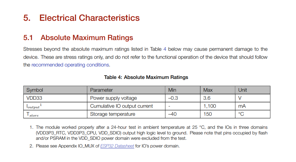
The operating voltage range for the ESP32 microcontroller is -0.3V to 3.6V. This means that the microcontroller can be powered using a voltage source within this range, and it will operate within its specified performance parameters.
Descriptions of Peripherals and Sensors for Reference click Here
- 1. General Purpose Input/Output Interface (GPIO)
: The ESP32 microcontroller features a General Purpose Input/Output Interface (GPIO), which provides a flexible and easy way to interface with external devices and circuits. GPIO pins can be used as inputs or outputs, and can be configured to perform a variety of functions depending on the requirements of the system.
- 2. AnalogtoDigital Converter (ADC)
The ESP32 is a microcontroller that features built-in support for an Analog-to-Digital Converter (ADC) module, which allows it to measure analog signals and convert them to digital values that can be processed by the device's processor.
- 3. DigitaltoAnalog Converter (DAC)
: The ESP32 microcontroller also features a built-in Digital-to-Analog Converter (DAC) module, which allows it to generate analog signals from digital values. The DAC module on the ESP32 consists of two channels, which can be used to generate two independent analog signals simultaneously.
- 4. Universal Asynchronous Receiver Transmitter (UART)
: The ESP32 microcontroller features multiple Universal Asynchronous Receiver Transmitter (UART) modules, which provide a simple and flexible way to transmit and receive data between the ESP32 and other devices using only two wires, a transmit line (TX) and a receive line (RX).
- 5. Serial Peripheral Interface (SPI)
: The ESP32 microcontroller features several Serial Peripheral Interface (SPI) modules, which provide a simple and efficient way to communicate with external devices using a synchronous serial protocol.
- 6. LED PWM: The ESP32 microcontroller includes a Pulse Width Modulation (PWM) module that can be used to generate PWM signals for controlling the brightness of LEDs, the speed of motors, and other applications. The ESP32 PWM module is capable of generating high-resolution PWM signals with up to 16 independent channels.
7.How many pins does the MCU have
The ESP32 microcontroller has a large number of pins, with the exact number varying depending on the specific model and package. The most common package for the ESP32 is the QFN (Quad Flat No-leads) package, which has a total of 48 pins. This includes 34 general-purpose input/output (GPIO) pins that can be used for a wide range of functions, such as controlling external devices, reading sensors, and communicating with other peripherals. In addition to the GPIO pins, the ESP32 also has a range of other pins dedicated to specific functions, such as power and ground, serial communication, analog inputs, and more. Some models of the ESP32 also have additional pins, such as USB interfaces or external memory interfaces. It's important to note that not all of the pins on the ESP32 are available for use in all applications, as some may be dedicated to specific functions or may be used for programming or debugging purposes. The specific pin configuration and functionality of the ESP32 will depend on the specific model and the requirements of the application. Regenerate response
8.How many GPIO pinsThe ESP32 microcontroller has a large number of General Purpose Input/Output (GPIO) pins, with the exact number varying depending on the specific model and package. The most common package for the ESP32 is the QFN (Quad Flat No-leads) package, which has a total of 48 pins. Of these 48 pins, 34 are general-purpose input/output (GPIO) pins that can be used for a wide range of functions, such as controlling external devices, reading sensors, and communicating with other peripherals. However, there are other ESP32 models with different packages and pin counts that offer a varying number of GPIO pins. For example, the ESP32-WROOM-32D module has 38 pins, of which 34 are GPIO pins. It's important to note that not all of the GPIO pins on the ESP32 are available for use in all applications, as some may be dedicated to specific functions or may be used for programming or debugging purposes. The specific pin configuration and functionality of the ESP32 will depend on the specific model and the requirements of the application. Regenerate response
B. Microcontroller development board to interact (with local input &/or output)
1.Output
In this assignment, The ESP32 has several output pins that can be configured as digital outputs, allowing the microcontroller to control external devices such as LEDs
- 1. Setting up the environment
: Before we can begin blinking an LED using an ESP32 microcontroller, we need to set up the development environment. This includes installing the Arduino IDE, adding the ESP32 board to the IDE, and installing the necessary libraries.
- 2. Wiring the LED
We need to wire the LED to the ESP32 microcontroller. We will connect the positive lead of the LED to a digital pin of the ESP32 and the negative lead of the LED to a ground pin.
- 3. Writing the code
: We will write the code for the ESP32 microcontroller using the Arduino IDE. We will define the pin to which the LED is connected, set it as an output pin, and write a program to toggle the pin high and low, thus blinking the LED.
- 4. Uploading the code
: We will upload the code to the ESP32 microcontroller using the Arduino IDE. We will connect the ESP32 to the computer via USB and select the correct board and port in the IDE. We will then click on the upload button to upload the code to the ESP32.
- 5. Testing the circuit
: Once the code is uploaded to the ESP32, we can test the circuit by observing the LED. The LED should blink at a regular interval. If the LED does not blink or blinks erratically, we may need to troubleshoot the circuit or the code.
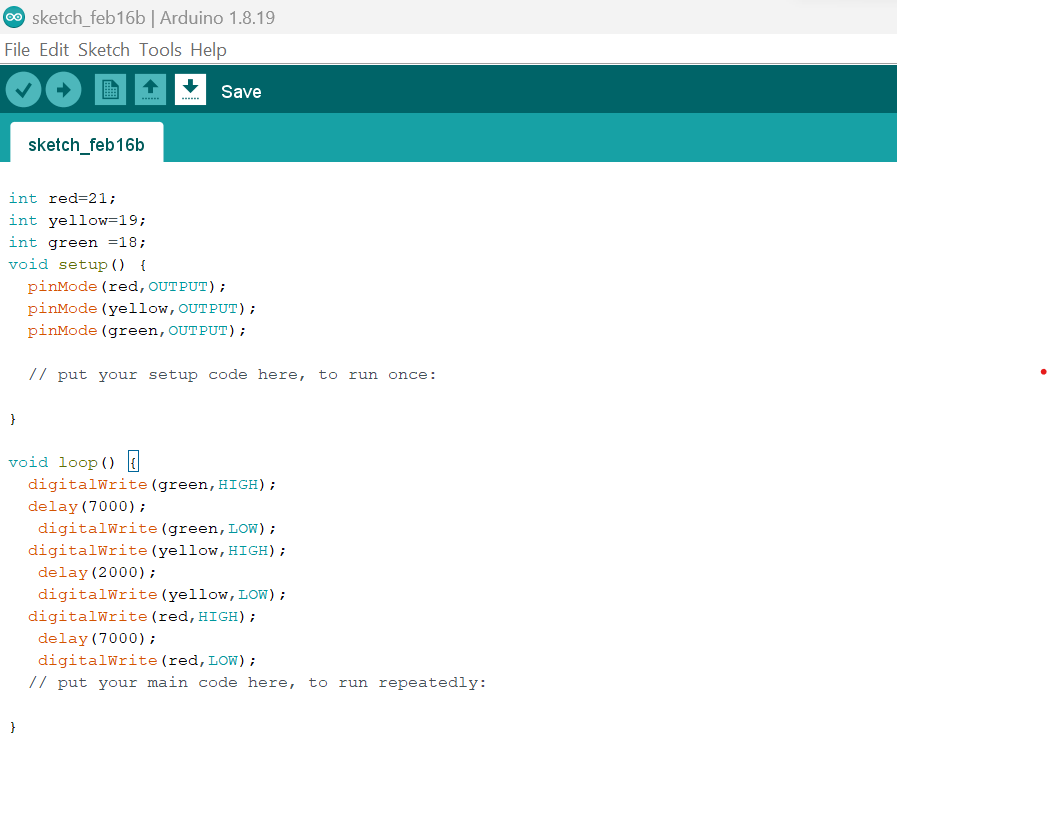
                                      int red=21;
                                      int yellow=19;
                                      int green =18;
                                      void setup() {
                                      pinMode(red,OUTPUT);
                                      pinMode(yellow,OUTPUT);
                                      pinMode(green,OUTPUT);

                                      // put your setup code here, to run once:

                                       }

                                        void loop() {
                                         digitalWrite(green,HIGH);
                                          delay(7000);
                                          digitalWrite(green,LOW);
                                          digitalWrite(yellow,HIGH);
                                           delay(2000);
                                           digitalWrite(yellow,LOW);
                                           digitalWrite(red,HIGH);
                                           delay(7000);
                                           digitalWrite(red,LOW);
                                            // put your main code here, to run repeatedly:

                                           }
2.Input
In this assignment, The ESP32 has several Input pins that can be configured as digital Inputs, allowing the microcontroller to control external devices such as Button
Blinking an LED using a button and an ESP32 microcontroller can be achieved by following these steps:
- 1. Connect the button and the LED to the ESP32 microcontroller.
: Connect the button to one of the digital input pins (e.g., pin 21) and connect the LED to one of the digital output pins (e.g., pin 19). You will also need to connect a current limiting resistor in series with the LED.
- 2. Write the code to blink the LED and read the button state.
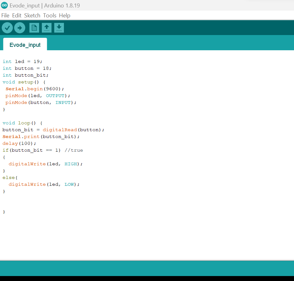
You can use the Arduino IDE to write and upload the code to your ESP32 microcontroller. Here's an example code to blink an LED connected to pin 21 and read the state of a button connected to pin 19 This code will blink the LED at a rate of one second on and one second off when the button is pressed. Additionally, it will print the state of the button to the serial monitor
- 3. Test the blinking and button reading
: Upload the code to the ESP32 microcontroller and test the blinking and button reading. Press the button to make the LED blink, and release the button to turn off the LED. The state of the button should also be printed to the serial monitor.
                                                     int led = 19;
                                                     int button = 18;
                                                     int button_bit;
                                                     void setup() {
                                                     Serial.begin(9600);
                                                     pinMode(led, OUTPUT);
                                                     pinMode(button, INPUT);
                                                      }

                                                     void loop() {
                                                     button_bit = digitalRead(button);
                                                     Serial.print(button_bit);
                                                     delay(100);
                                                     if(button_bit == 1) //true
                                                      {
                                                     digitalWrite(led, HIGH);
                                                      }
                                                     else{
                                                     digitalWrite(led, LOW);
                                                      }
                                                      }
3.Connecting remotely
Blinking an LED using an ESP32 microcontroller and a Bluetooth module can be achieved by following these steps:
- 1. Connect the ESP32 microcontroller and the Bluetooth module.
: You will need to connect the Bluetooth module to the ESP32 microcontroller. Depending on the specific modules you are using, you may need to connect specific pins between the two devices. Consult the datasheets and documentation for your hardware for the specific connections.
- 2. Write the code to blink the LED
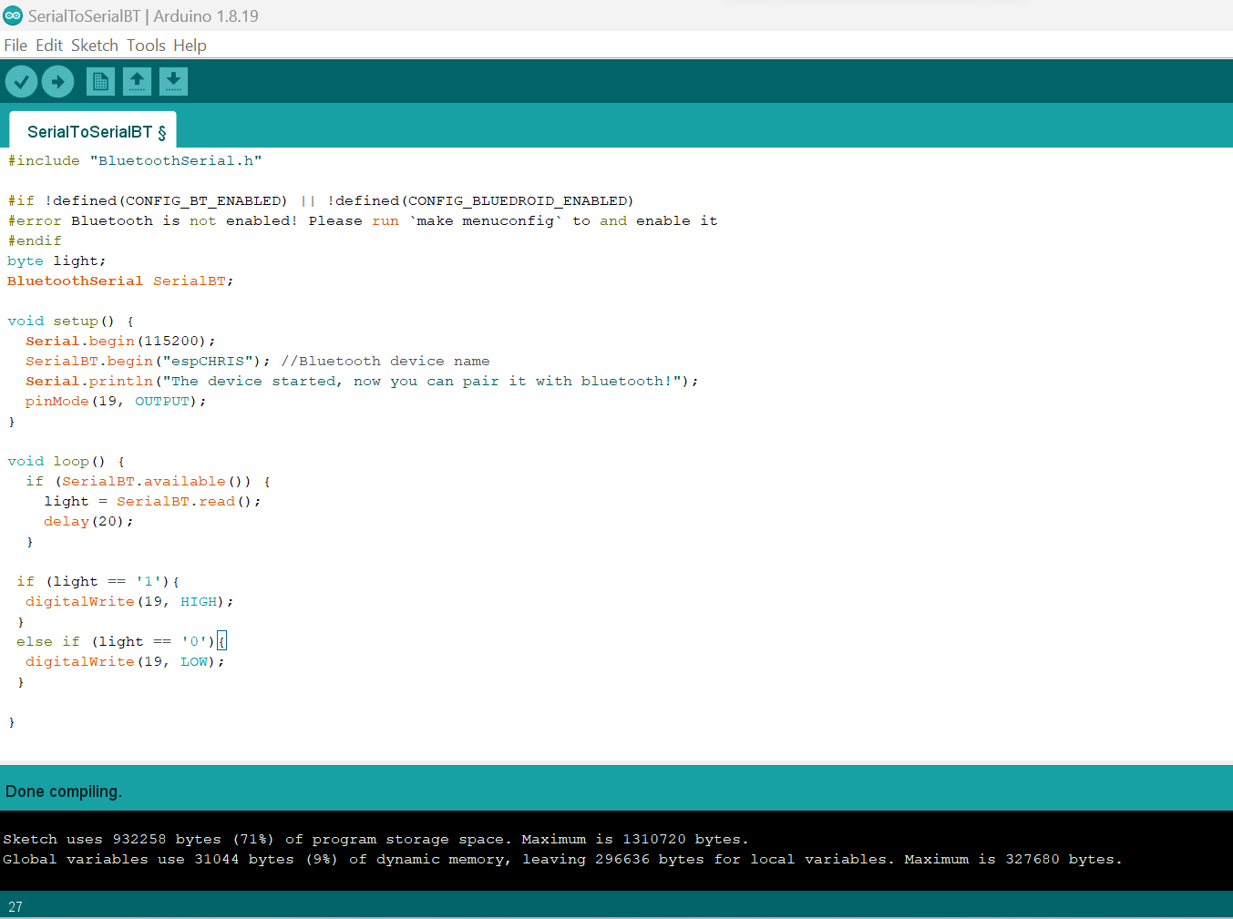
We use the Arduino IDE to write and upload the code to your ESP32 microcontroller. That code will blink the LED at a rate of one second on and one second off. Additionally, it will listen for input from the serial Bluetooth terminal. If it receives a '1', it will turn the LED on. If it receives a '0', it will turn the LED off
- 3. Connect to the ESP32 microcontroller using the Bluetooth module
: Use a serial Bluetooth terminal app on your phone or computer to connect to the Bluetooth module. Once connected, you should be able to send commands to the ESP32 microcontroller using the app.
- 4. Test the blinking and control of the LED
: Send the '1' and '0' commands to the ESP32 microcontroller using the serial Bluetooth terminal app to test the control of the LED. The LED should turn on and off in response to the commands.
Here are the code we run in Arduino
                                                      #include "BluetoothSerial.h"

                                                      #if !defined(CONFIG_BT_ENABLED) || !defined(CONFIG_BLUEDROID_ENABLED)
                                                      #error Bluetooth is not enabled! Please run `make menuconfig` to and enable it
                                                      #endif
                                                      byte light;
                                                      BluetoothSerial SerialBT;

                                                      void setup() {
                                                      Serial.begin(115200);
                                                      SerialBT.begin("espCHRIS"); //Bluetooth device name
                                                      Serial.println("The device started, now you can pair it with bluetooth!");
                                                      pinMode(19, OUTPUT);
                                                      }

                                                      void loop() {
                                                      if (SerialBT.available()) {
                                                      light = SerialBT.read();
                                                      delay(20);
                                                      }

                                                      if (light == '1'){
                                                      digitalWrite(19, HIGH);
                                                      }
                                                       else if (light == '0'){
                                                      digitalWrite(19, LOW);
                                                      }

                                                    }
If you want to learn about my code, kindly click here