Week 8: Electronic Production
Group assignment
Characterize the design rules for your in-house PCB production processIndividual assignment
-
Make and test the development board that you designed to interact and communicate with an embedded microcontroller
I am going to make the CH340G USB to interact and communicate with my ESP-WROM-32 BOARD.
What is a CH340G USB?
The CH340G USB is a type of USB to serial converter IC (integrated circuit) that enables a computer to communicate with and program microcontrollers, such as those commonly found on Arduino boards.
What is a ESP-WROM-32 BOARD?
The ESP-WROOM-32 board is a low-cost, low-power consumption device used for Internet of Things (IoT) applications. It is based on the ESP32 system-on-a-chip (SoC) and offers WiFi and Bluetooth connectivity, as well as several digital and analog input/output (I/O) pins for connecting to sensors and other devices. It can be programmed using various programming languages and development environments, making it a popular choice for IoT projects. With the use of KiCad, I am going to generate a PCB layout by arranging the components onto the board and establishing the connections between them through routing the traces, all based on the schematic diagram.
What is Kicad?
KiCad is an EDA (Electronic Design Automation) software suite that operates as an open-source platform. It is equipped to manage Schematic Capture and PCB Layout processes, and it produces Gerber output. This suite can be utilized on various operating systems such as Windows, Linux, and macOS, and it is licensed under the GNU GPL v3.For more about Kicad visit here .
Creating an electrical circuit.
Having the software installed in the computer, lunch it to initiate a new project
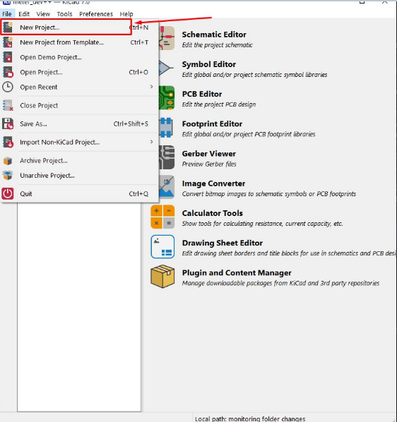
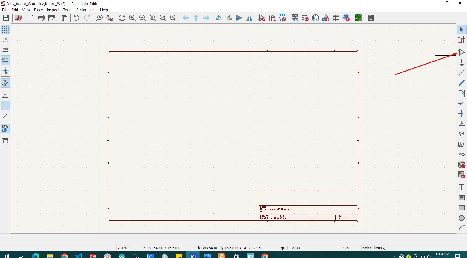
Once I established a new project in the KiCad project format, I accessed the KiCad user interface schematic editor.
To locate the necessary symbol components, I clicked on the below mentioned icon, which opened the symbol components library.
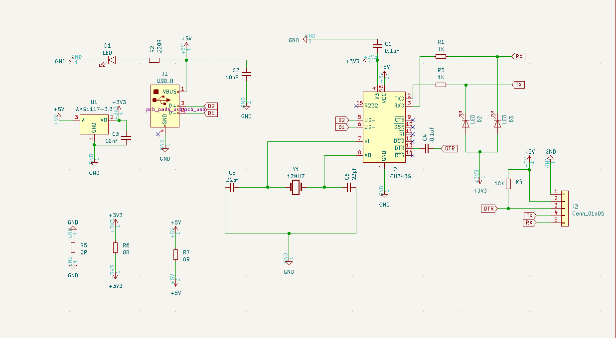
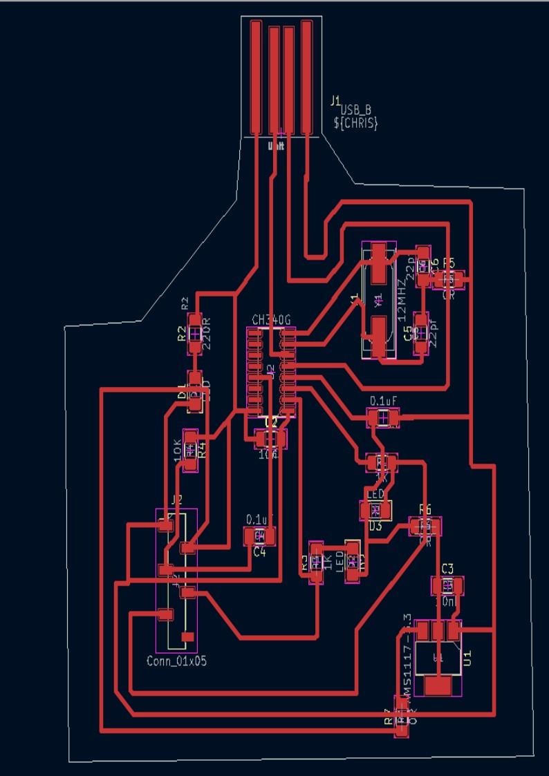
II then place all needed components, as show on the below schematic circuit
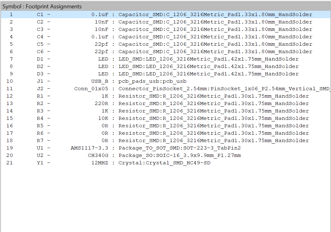
Below here is the list of all used components:
Here after is the then created PCB
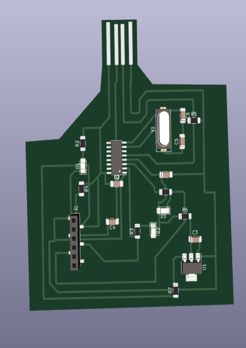
This the resulted PCB in 3D view
Below here is the SVG file generated from KiCARD
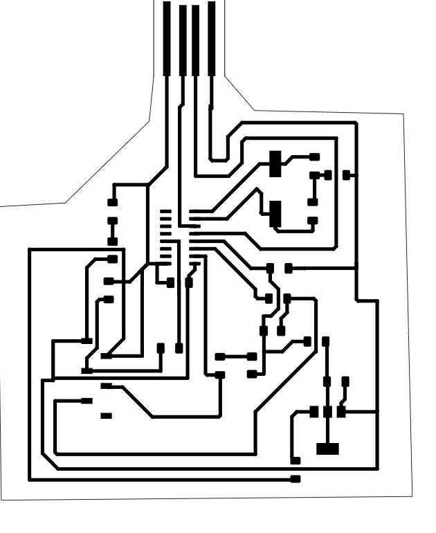
I use this tool mods.cba.mit.edu to produce Gerber files which hold crucial information such as component dimensions and positioning, trace routing, and other relevant details necessary for PCB creation.
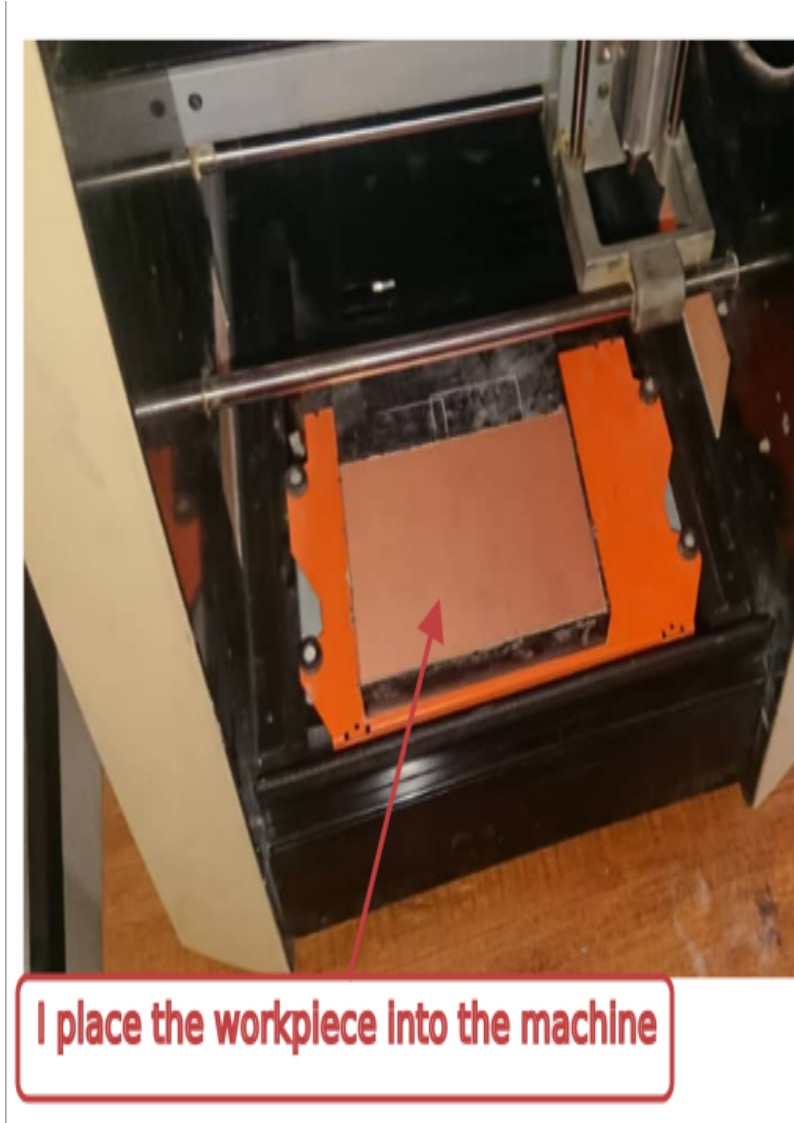
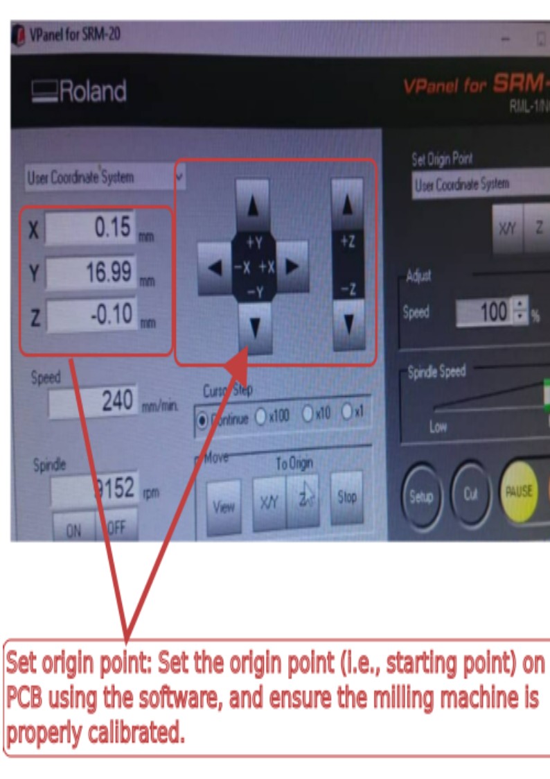
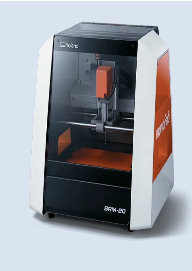 This the used monoFab SRM-20 Desktop Milling Machine available in our lab. |
|
|
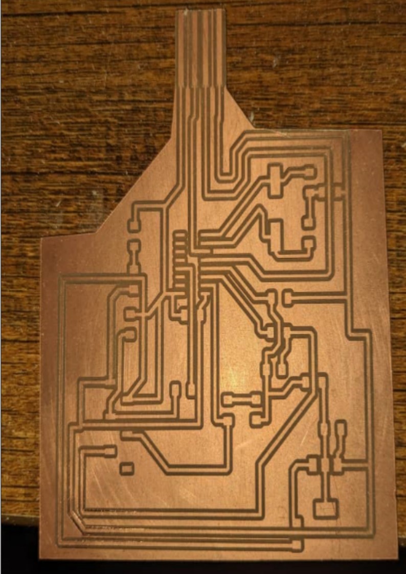
This the generated PCB after milling process
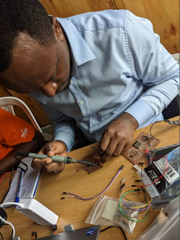
Soldering components on the board, and I have to use more caution to prevent short circuits.
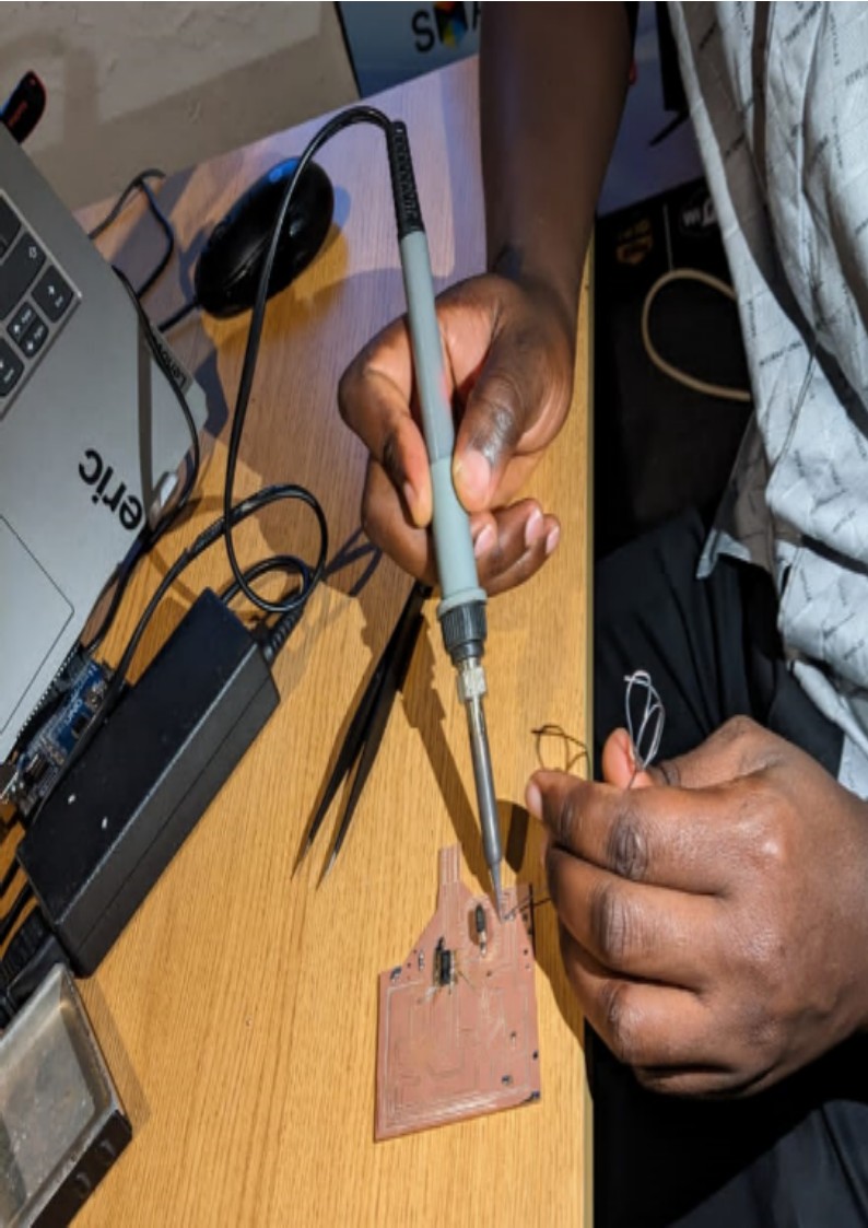
Almost done with soldering, and here I am soldering wires on the connector to serve as connetion of ESP 32 ESPROM and CH340G, the Avr Programmer.
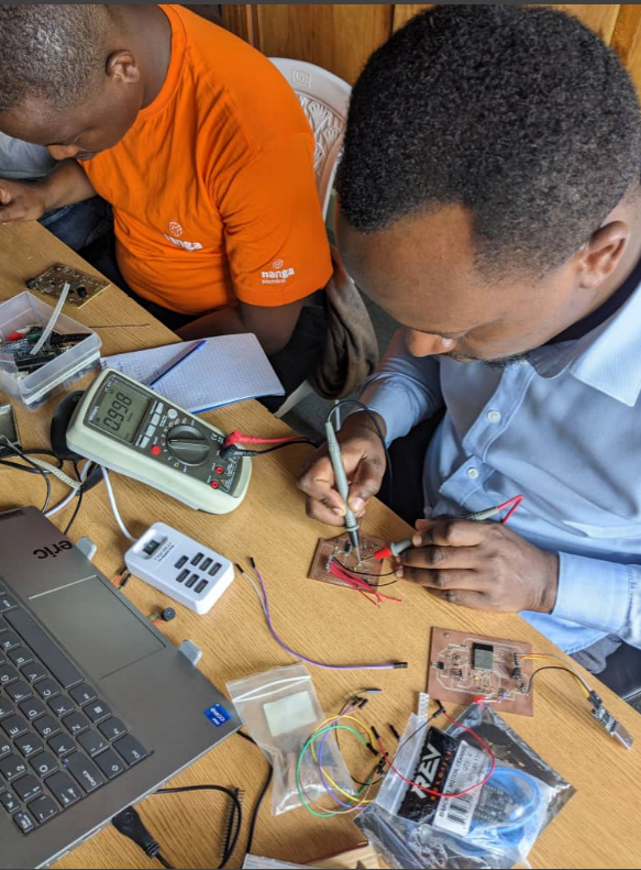
I then did so many testing, like here below I am testing the used to 10K resistor
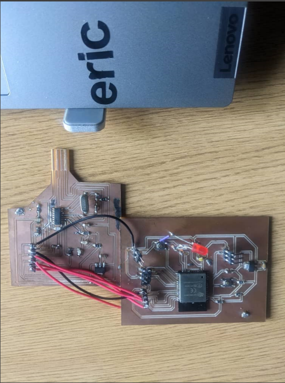
Below here is the made Avr programmer connected to the made board with ESP 32 IC (microcontroller)
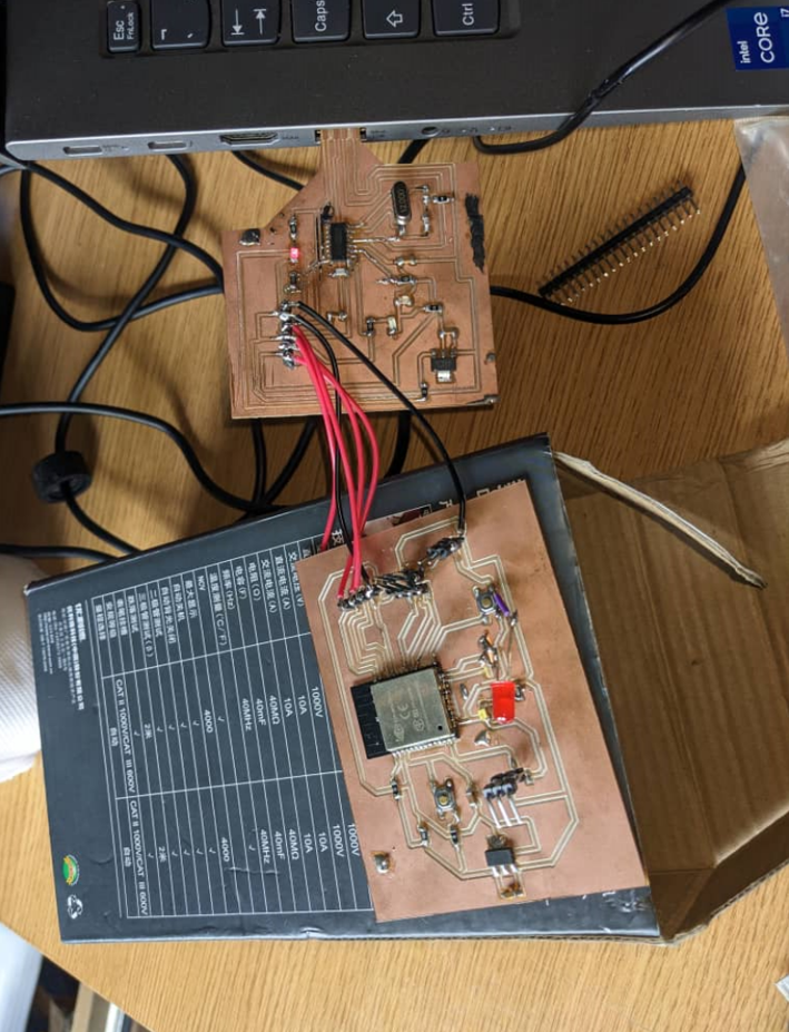
As shown on the picture below, the made board with ESP 32 IC (microcontroller) is connected to the laptop PC through the above made Avr programmer.
The LED is ON, and there is a detection sound.
Unfortunately, the device is not recognized by the computer.
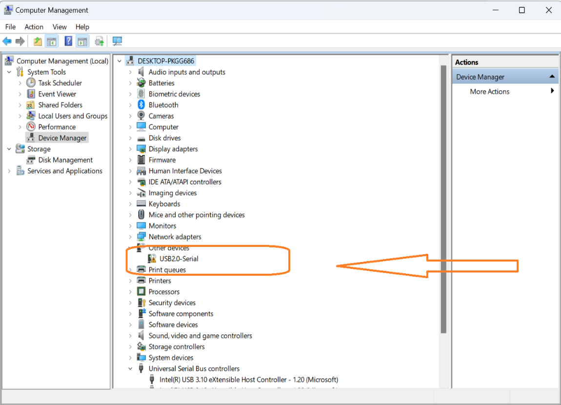
To fix the issue, I had to download and install Ch340G drivers on this link
The drivers have now been updated, as evidenced by the screenshot below.
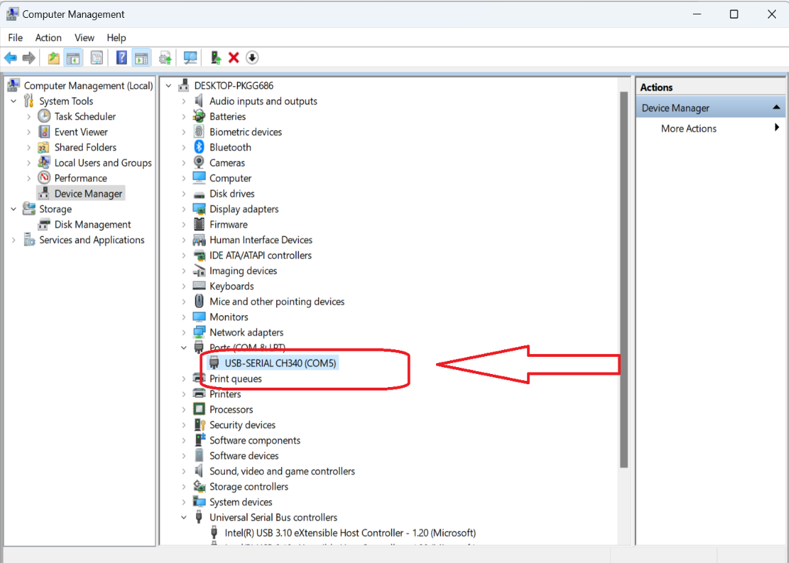
Finally, it is functional! As it is shown, now the made CH340G USB is able to program my ESP-WROM-32 BOARD!
- Used file can be found here
© 2023 | Eric NDAYISHIMIYE | All Rights Reserved