Week 4: Embedded Programming
Assignment activities
Group assignment
Compare the performance and development workflows for other architectures
Individual assignment
Browse through the data sheet for your microcontroller program a microcontroller development board to interact and communicate.
For week4 activities I choose to use DOIT ESP32 DEVKIT V1 microcontroller.
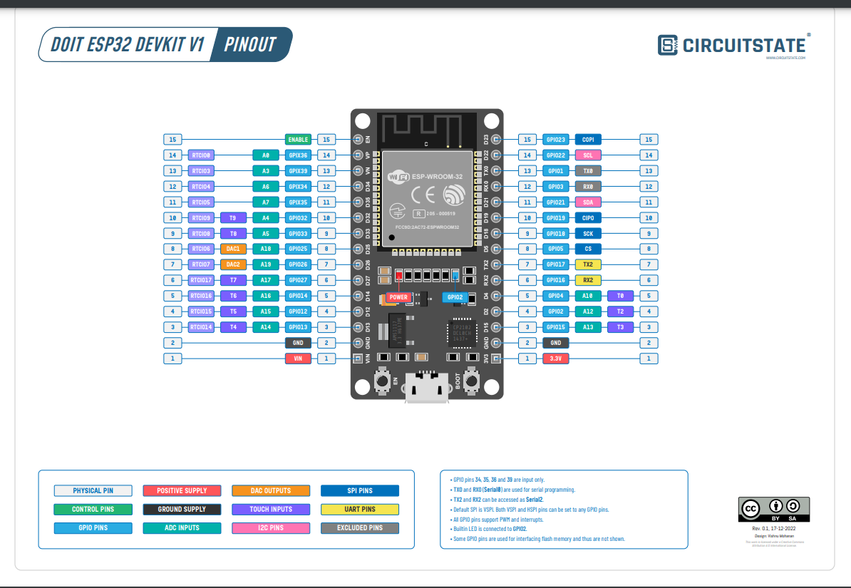
1. Browse through the datasheet for DOIT ESP32 DEVKIT V1
The DOIT ESP32 DevKit V1 is a microcontroller board based on the ESP32 system-on-chip (SoC) from Espressif Systems. The ESP32 is a powerful, low-cost, low-power Wi-Fi and Bluetooth-enabled microcontroller that is widely used in Internet of Things (IoT) applications.
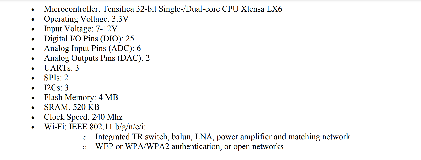
The DOIT ESP32 DevKit V1 board is designed to provide an easy-to-use platform for developing and prototyping IoT applications. It features a dual-core Tensilica LX6 microprocessor with clock speeds of up to 240 MHz, 520KB of SRAM, 4MB of flash memory, and a range of peripheral interfaces, including I2C, SPI, UART, and ADC. The board also includes a built-in Wi-Fi and Bluetooth module, making it easy to connect to the internet and other devices.
The DOIT ESP32 DevKit V1 is compatible with the Arduino IDE, which allows developers to write and upload code to the board using the Arduino programming language. It also supports the MicroPython and Lua programming languages, giving developers additional options for coding their applications.
The board is powered by a micro-USB port and has a 3.3V regulator to provide stable power to connected peripherals. It also has a reset button, a user-programmable button, and a user-programmable LED.
Overall, the DOIT ESP32 DevKit V1 is a versatile and powerful microcontroller board that is well-suited for a wide range of IoT applications, including home automation, sensor networks, and robotics.
Some highlights on the datasheet:
For this microcontroller, what I have read in datasheet is all about the High Performance,
Low Power AVR® 8-bit Microcontroller(), that are convenient for running simple programs.
The DOIT ESP32 DevKit V1 does not have legs, as it is a microcontroller board designed for electronic
prototyping and development. However, the board has a number of pins and connectors that can be used to
interface with other electronic components and devices, such as sensors, actuators, and other microcontrollers.
The exact number and types of pins and connectors on the board depend on the specific version and model of the
board, but the DOIT ESP32 DevKit V1 typically has a range of digital and analog input/output pins, power and
ground pins, and communication interfaces such as I2C, SPI, and UART.
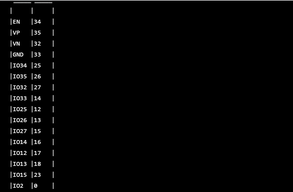
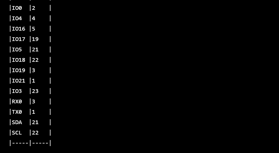
Device Summary
The DOIT ESP32 DevKit V1 is compatible with the Arduino IDE and can be programmed using the Arduino programming
language. It has a number of pins that can be used for digital and analog input and output, as well as for
communication with other devices. The pinout for the board is as follows:
2. Programming the DOIT ESP32 DEVKIT V1 microcontroller for the first time using Arduino IDE 1.6.7
- - Install Arduino IDE 1.6.7 on your computer. You can download it from the official Arduino website.
-
- In Arduino IDE, I click on File tab, and then choose Preferences
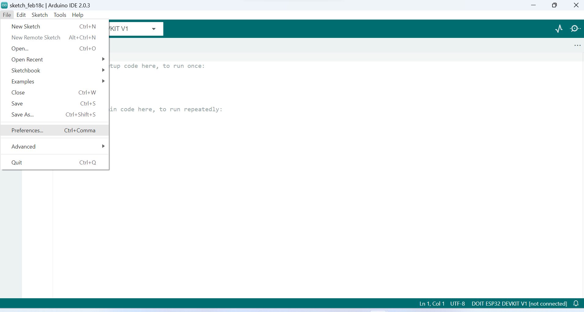
-
- Enter the following into the “Additional Board Manager URLs” field:
https://raw.githubusercontent.com/espressif/arduino-esp32/gh-pages/package_esp32_index.json
Then, click the “OK” button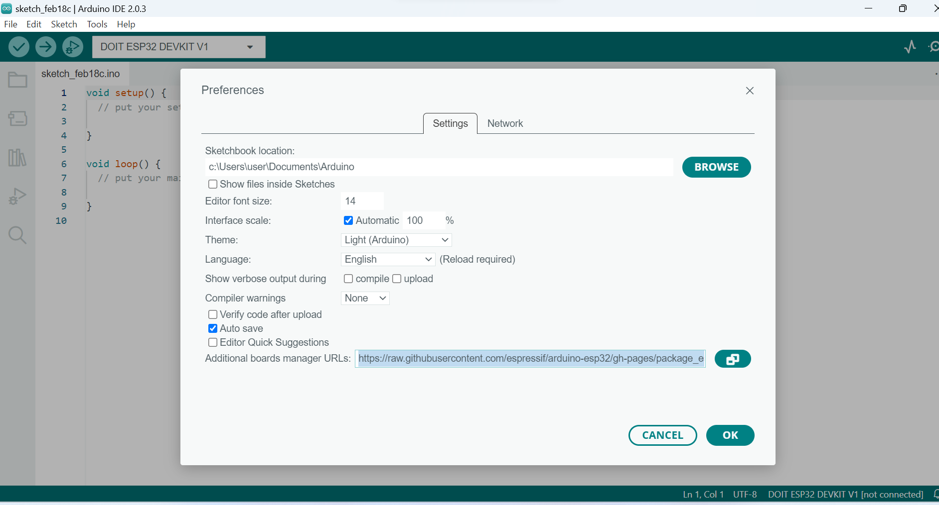
-
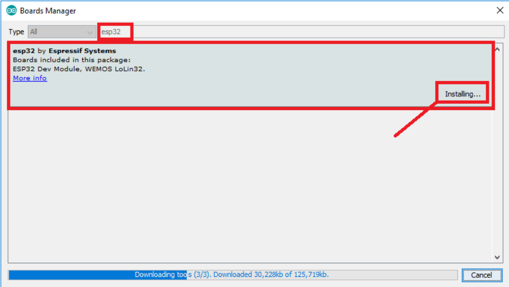
- Open the Boards Manager: I click on Tools > Board > Boards Manager…
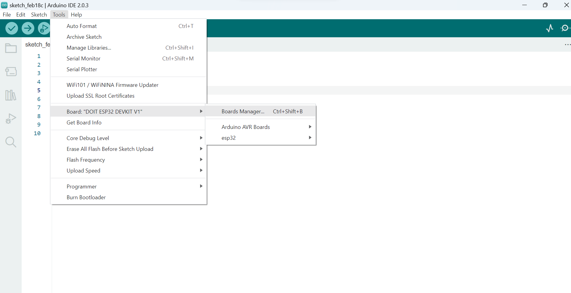
-
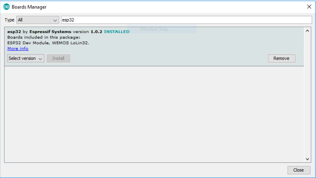
- That’s it. It should be installed after a few seconds:
- - Plug the ESP32 board to your computer. With your Arduino IDE open, follow these steps:
-
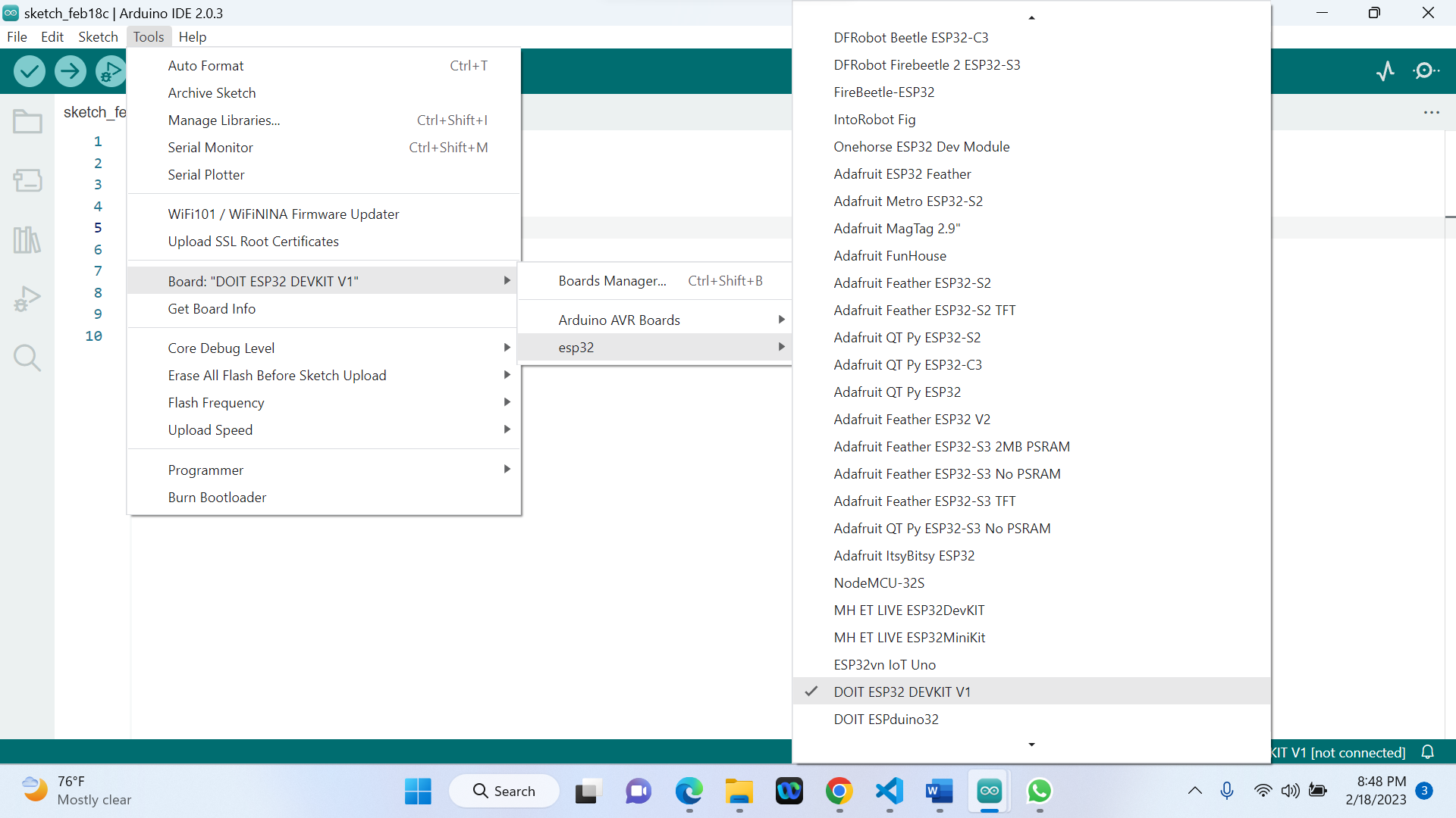
- Select your Board in Tools > Board menu (in my case it’s the DOIT ESP32 DEVKIT V1)
-
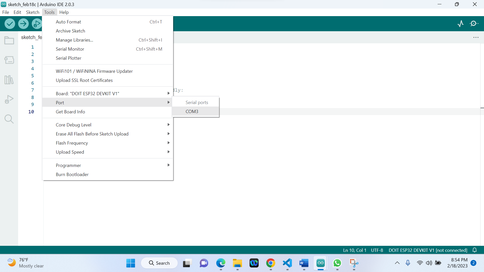
- Select the port
-
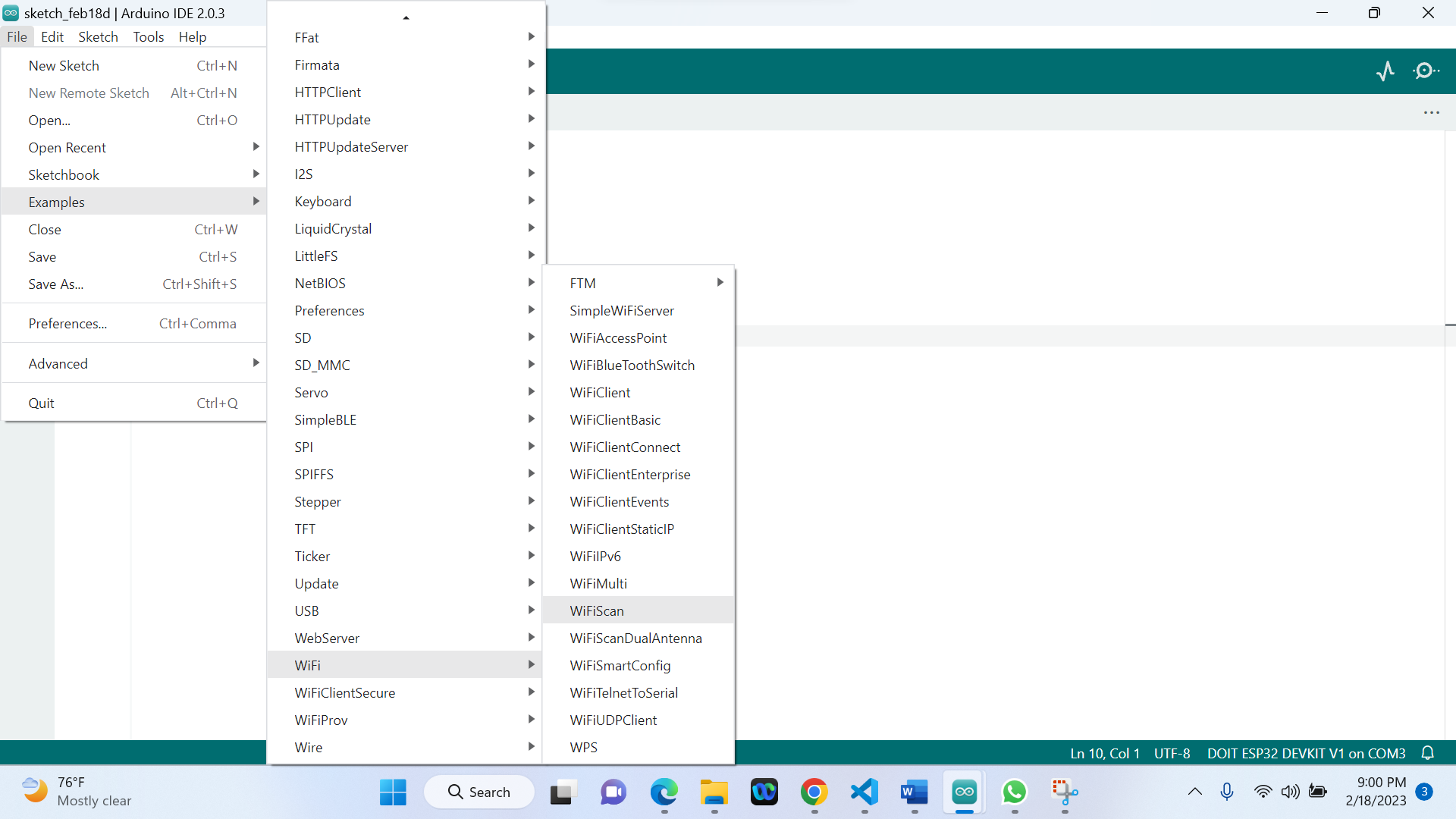
- Open the following example under File > Examples > WiFi (ESP32) > WiFiScan
-
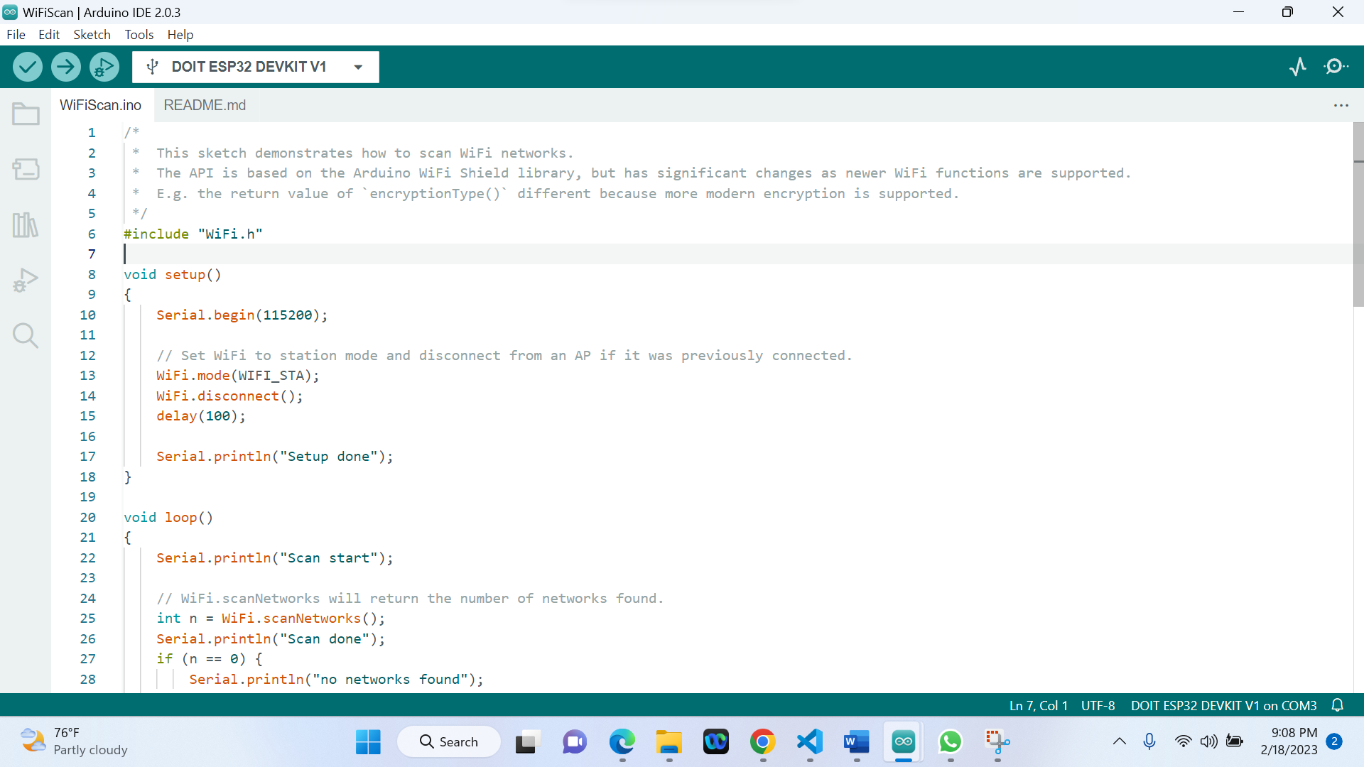
- A new sketch opens in Arduino IDE
-
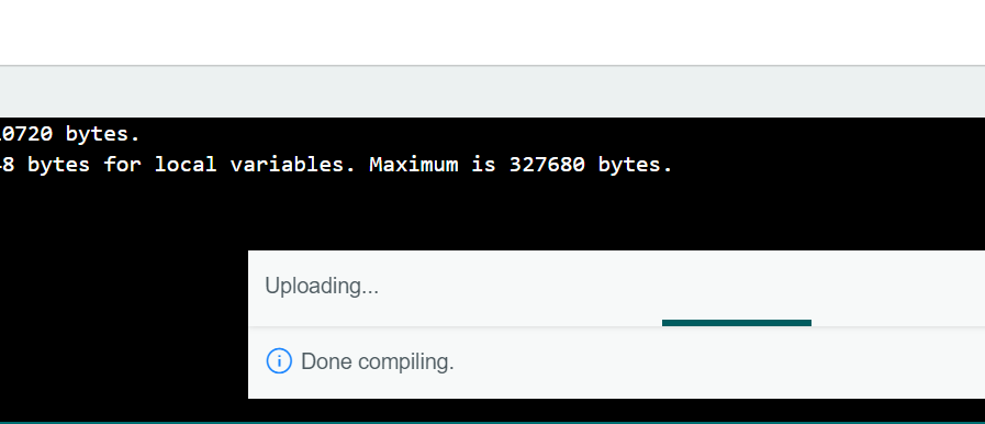
- Press the Upload button in the Arduino IDE. Wait a few seconds while the code compiles and uploads
to your board.

-
- If everything went as expected, you should see a “Done uploading.” message
-
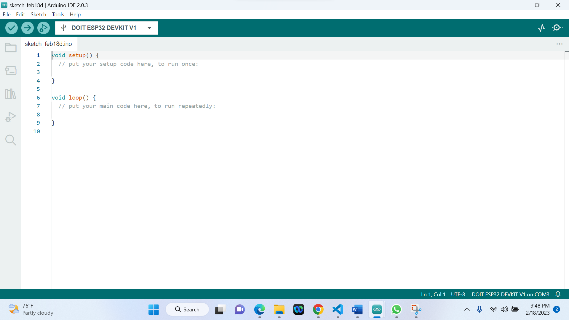
Step1: Starting the Arduino IDE/ creating a new document
-
Step2: Declaration of global variable //outside Setup fuction:
Define the pins for the traffic light: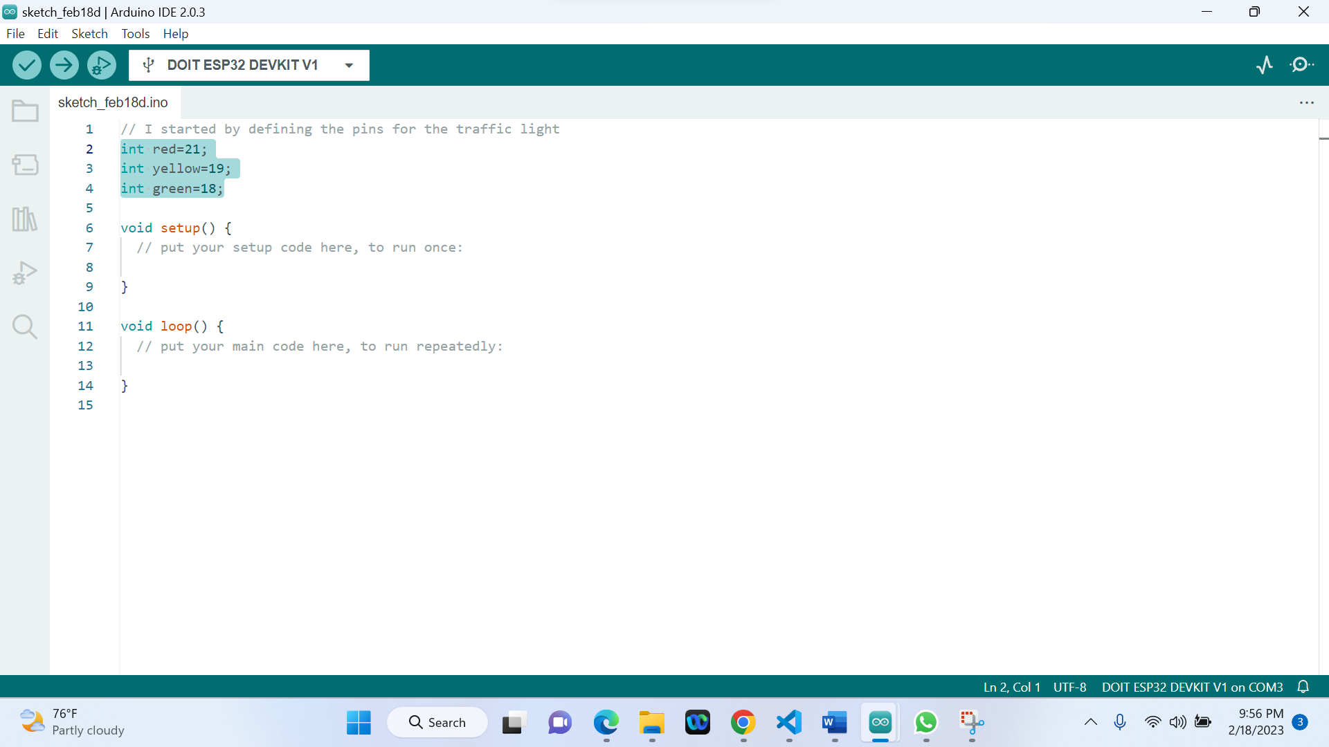
-
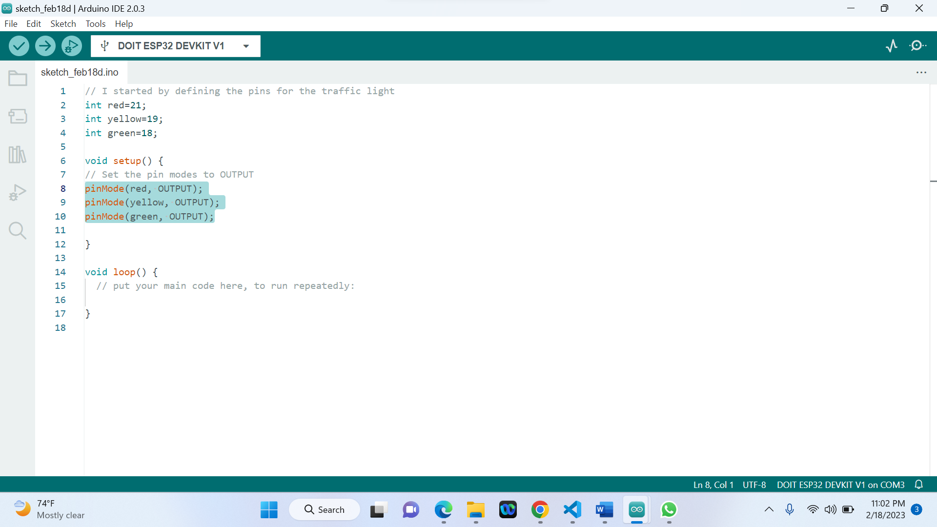
Step3: Set the pin modes to OUTPUT //Inside Setup fuction
-
Step4: Cooding for wanted/resulting outputs//Inside loop fuction
1) Red light for 10 seconds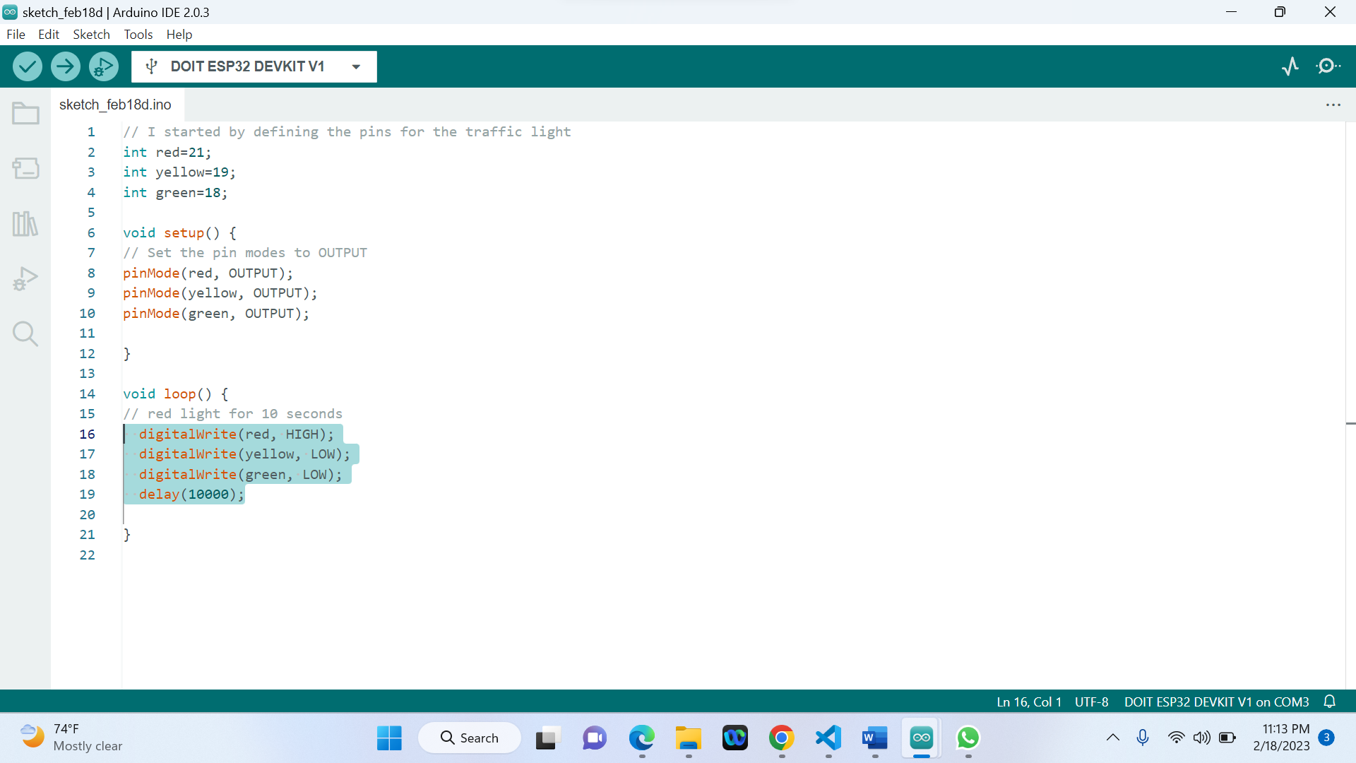
-
2) Yellow light for 3 seconds
-
3) Green light for 10 seconds
-
3) Yellow light for 3 seconds
-
- I Search for DOIT ESP32 DevKit V1 and press install button:
-
Testing the Installation:
Using C++ I write a program for a road traffic light using the Arduino IDE!
Below here is the used code:
// I started by defining the pins for the traffic light
int red=21;
int yellow=19;
int green=18;
void setup() {
// Set the pin modes to OUTPUT
pinMode(red, OUTPUT);
pinMode(yellow, OUTPUT);
pinMode(green, OUTPUT);
}
void loop() {
// Red light for 10 seconds
digitalWrite(red, HIGH);
digitalWrite(yellow, LOW);
digitalWrite(green, LOW);
delay(10000);
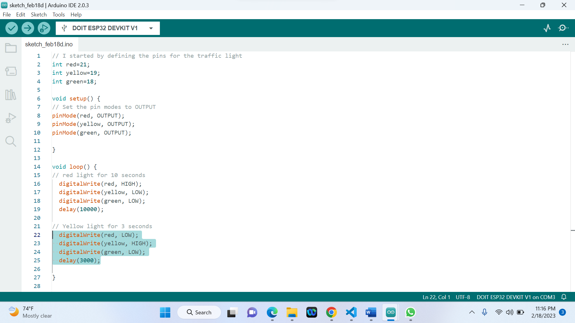
// Yellow light for 3 seconds
digitalWrite(red, LOW);
digitalWrite(yellow, HIGH);
digitalWrite(green, LOW);
delay(3000);
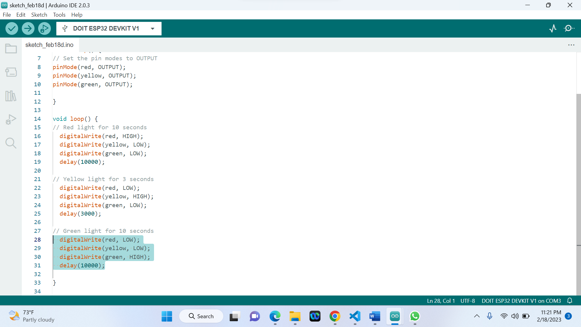
// Green light for 10 seconds
digitalWrite(red, LOW);
digitalWrite(yellow, LOW);
digitalWrite(green, HIGH);
delay(10000);
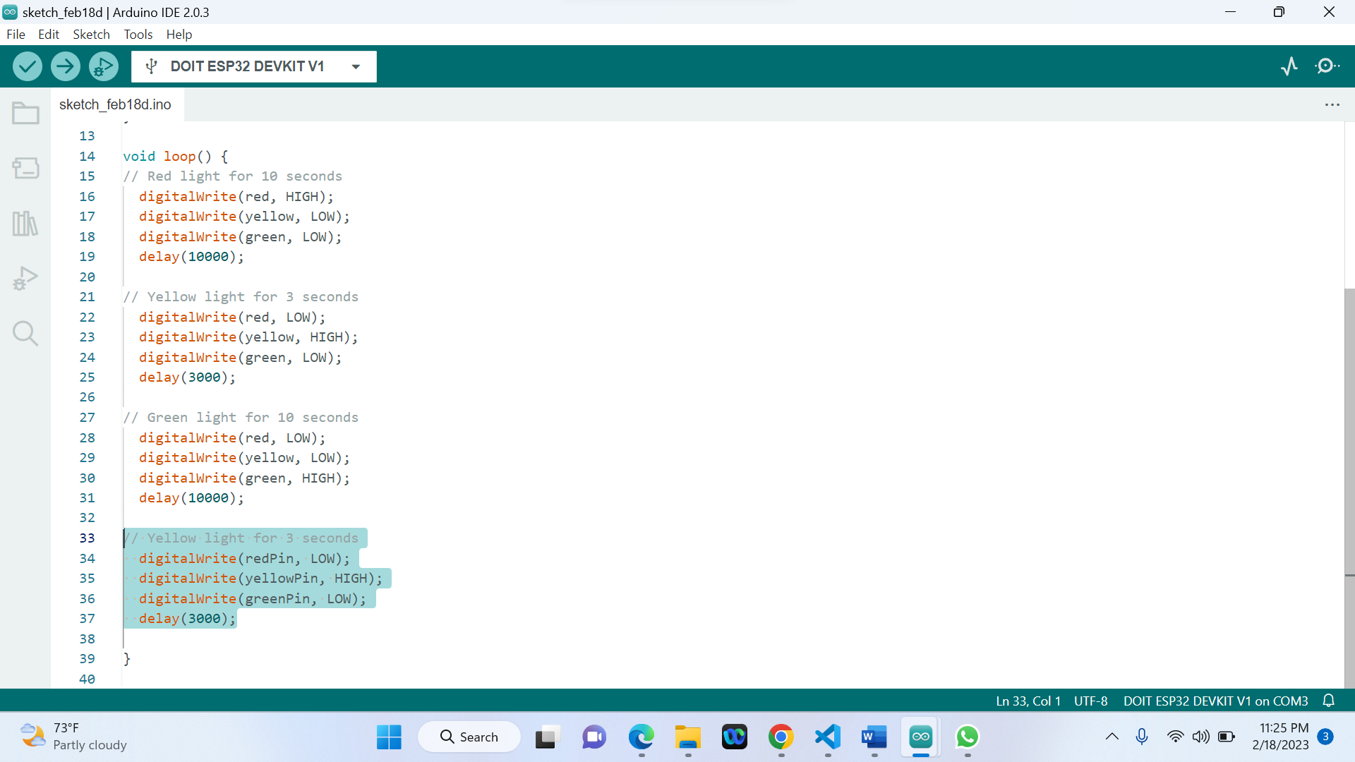
// Yellow light for 3 seconds
digitalWrite(redPin, LOW);
digitalWrite(yellowPin, HIGH);
digitalWrite(greenPin, LOW);
delay(3000);
}
Above here, is a program for controlling a traffic light using an Arduino board. The program defines the pins for the traffic light (red, yellow, and green) and specifies the sequence and timing of the traffic light signals.
|
1. First, the pins for the traffic light are defined using the "int" data type. The pin numbers correspond to the physical pins on the Arduino board that are connected to the traffic light. |
2. In the "setup()" function, the pin modes are set to OUTPUT using the "pinMode()" function. This tells the Arduino board to send signals to the traffic light on these pins. |
3. In the "loop()" function, the sequence and timing of the traffic light signals are specified using the "digitalWrite()" and "delay()" functions. |
|
4. The program starts by turning on the red light for 10 seconds using "digitalWrite(red, HIGH)" to send a high voltage signal to the red pin. The yellow and green lights are turned off using "digitalWrite(yellow, LOW)" and "digitalWrite(green, LOW)" respectively. The program then waits for 10 seconds using the "delay(10000)" function. |
5. Next, the yellow light is turned on for 3 seconds using "digitalWrite(yellow, HIGH)" while the red and green lights are turned off using "digitalWrite(red, LOW)" and "digitalWrite(green, LOW)" respectively. The program then waits for 3 seconds using "delay(3000)". |
6. The green light is then turned on for 10 seconds using "digitalWrite(green, HIGH)" while the red and yellow lights are turned off using "digitalWrite(red, LOW)" and "digitalWrite(yellow, LOW)" respectively. The program then waits for 10 seconds using "delay(10000)". |
Finally, the yellow light is turned on for 3 seconds using "digitalWrite(yellow, HIGH)" while the red and green lights are turned off using "digitalWrite(red, LOW)" and "digitalWrite(green, LOW)" respectively. The program then waits for 3 seconds using "delay(3000)".
The following is the video showing the board while interacting and communicating with the LED:
The following is the video showing the board while interacting and communicating with the LED:
The following is the video showing the board while interacting and communicating with the LED:
-
Used file can be found here
© 2023 | Eric NDAYISHIMIYE | All Rights Reserved