INTERFACE AND APPLICATION PROGRAMING
This week I learned how:
1.How we can use Python and download pyserial so we can communicate from any Python programs like Pycharm , with the tkinter library to make a User Interface UI, as well as, VPython library helps to create navigable 3D displays and animations easily.
2.How Firefly and this a addon for grasshopper in Rhino and we can use it in many different ways such as creating an interface with just the sound of the sea and much more.
3.The MIT app inventor is a visual programming environment that allows everyone to build fully functional apps for smartphones and tablets. It use blocks-based tool facilitates the creation of complex, high-impact apps in significantly less time than traditional programming environments. The MIT App Inventor project seeks to democratize software development by empowering all people, especially young people, to move from technology consumption to technology creation.
Group Assignment
Here in this week we were asked to Compare as many tool options as possible
Here is the link to explore more
Individual assignement
What i do in this week
n this assignment I wanted to make an interface which displays the level of magnet sensed by the hall effect sensor. As the hall effect sensor is used in different applications.
Process to Designing PCB to use
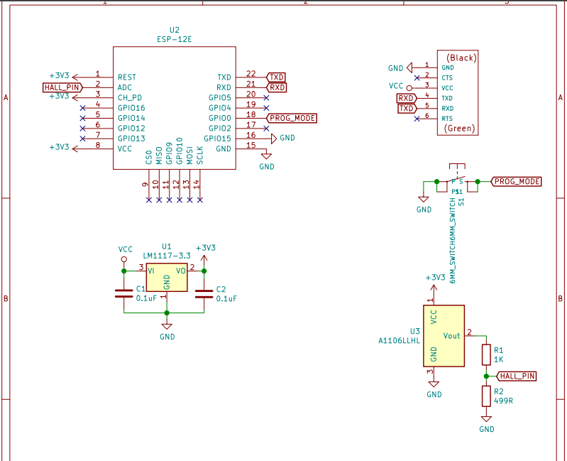
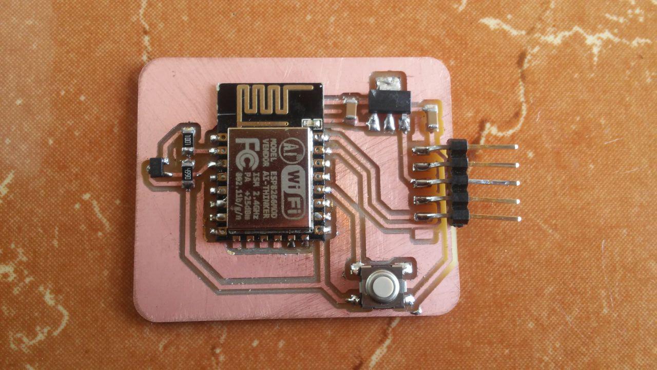
I started by designing the PCB I wanted to use in this assignment. My circuit was made of ESP8266 as the microcontroller of the system and a hall effect sensor which measures the level of magnetism as shown below.
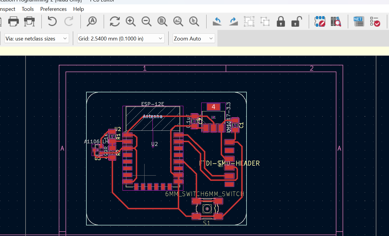
From the circuit schematic I designed a PCB board after Arranging and connecting every components as shown in the image below.
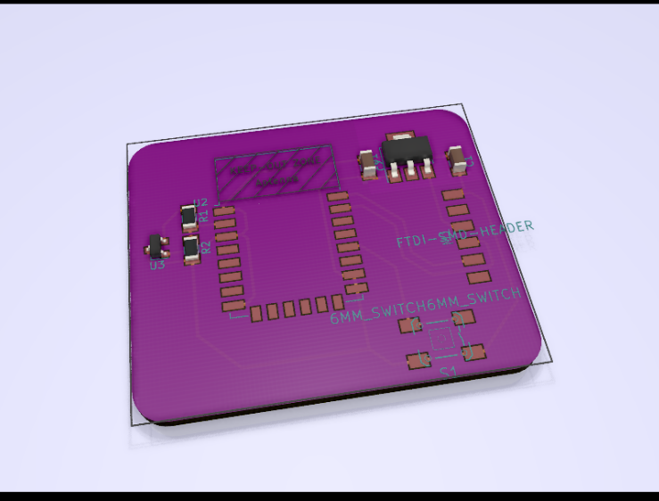
Since I was using KiCAD in designing and it enables me to see a 3D render board which look nearly to the final board I will get.
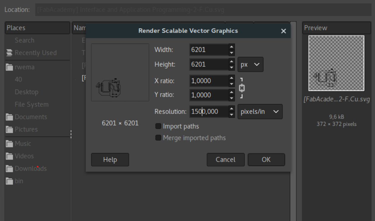
After designing I export the board design as an image with an SVG format which is the one KiCAD provides, after that I had to convert to PNG which I can use with fabmodules to generate an RML file to use in Roland machine while milling. I imported the SVG file in GIMP, increased its resolution as shown below.
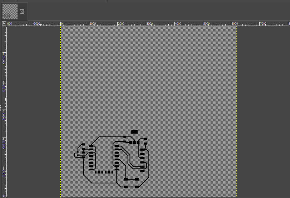
This is how the trace SVG image looks after importing it in GIMP.
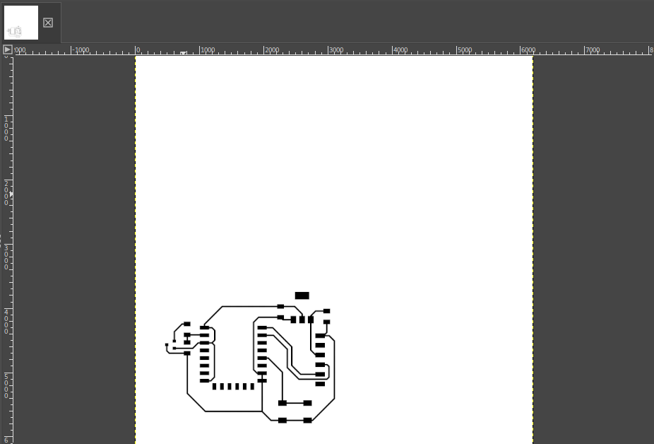
Here on this step I filled the background of the image with a white color and saved it as a PNG.
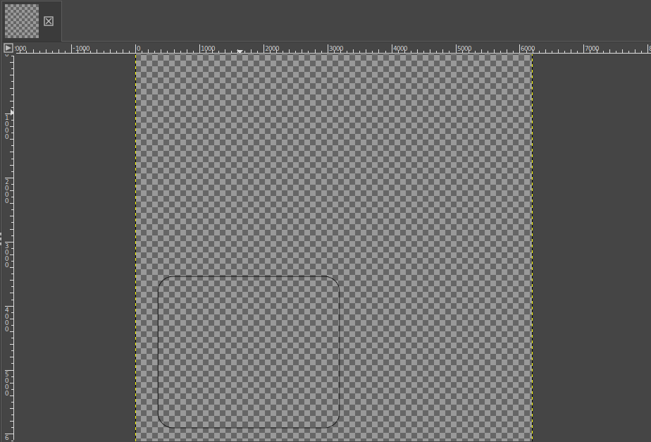
I also imported the layout image and you can see it is only a single line which make the layout.
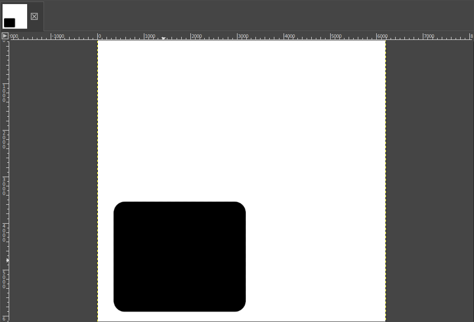
I filled the outer background of the image with a white color and the inner background with a black color and saved it as PNG.
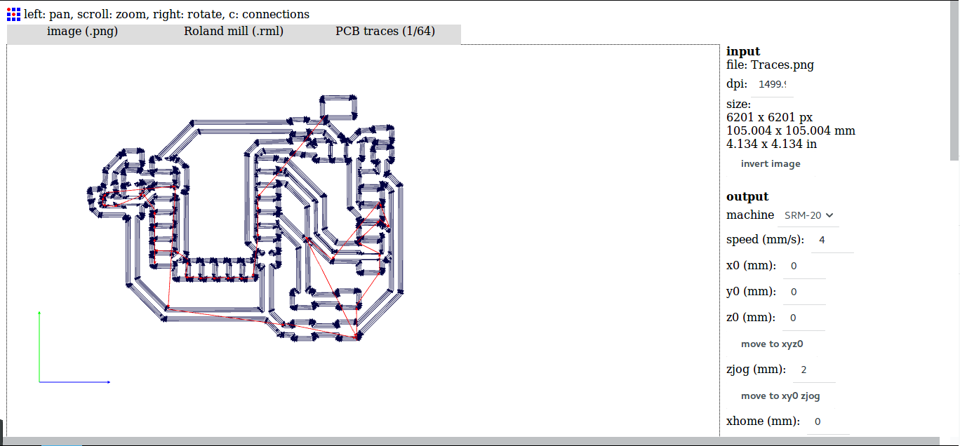
I imported the images in fabmodules to convert them but first I had to invert the image so the milling will be done in the right place.
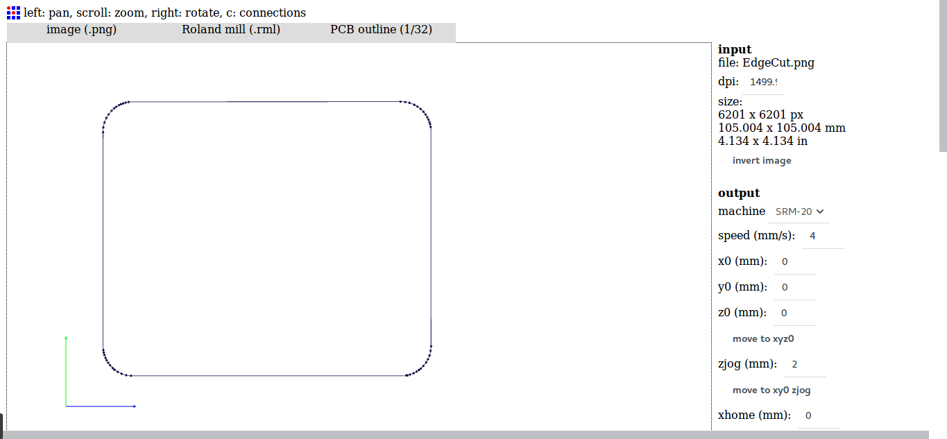
I did the same for the layout image which I imported and inverted the image color generated the RML file for.
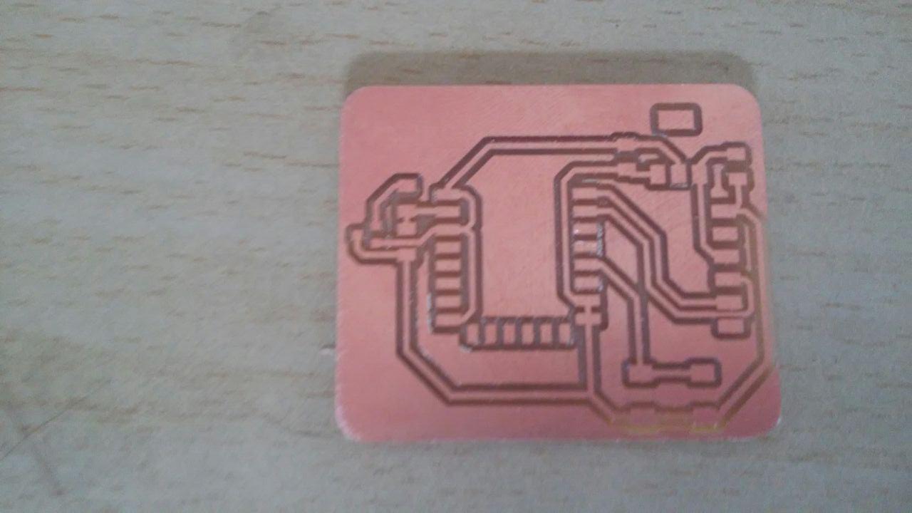
I went on and milled the board with the Roland machine, and this is my board after milling it.
Here on this image is after soldering the board
Designing Interface
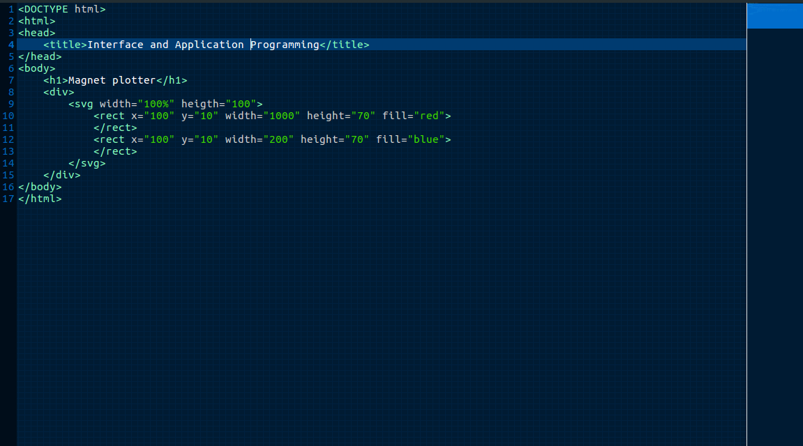
As discribed above I want to display the level of magnetism on the web page, I used ESP8266 to do that. I have first tested the program of the web page I wanted to create in my computer. I wrote an html program and tested it as shown below.
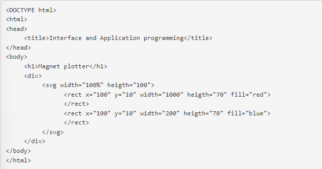
This is the program I wrote using gedit text editor. In this program I created two SVG squares the blue one obove the red one. The way I used to show the magnitude of the part I measuring, was to vary the size of the blue rectangle depending on the value read from the hall effect sensor.
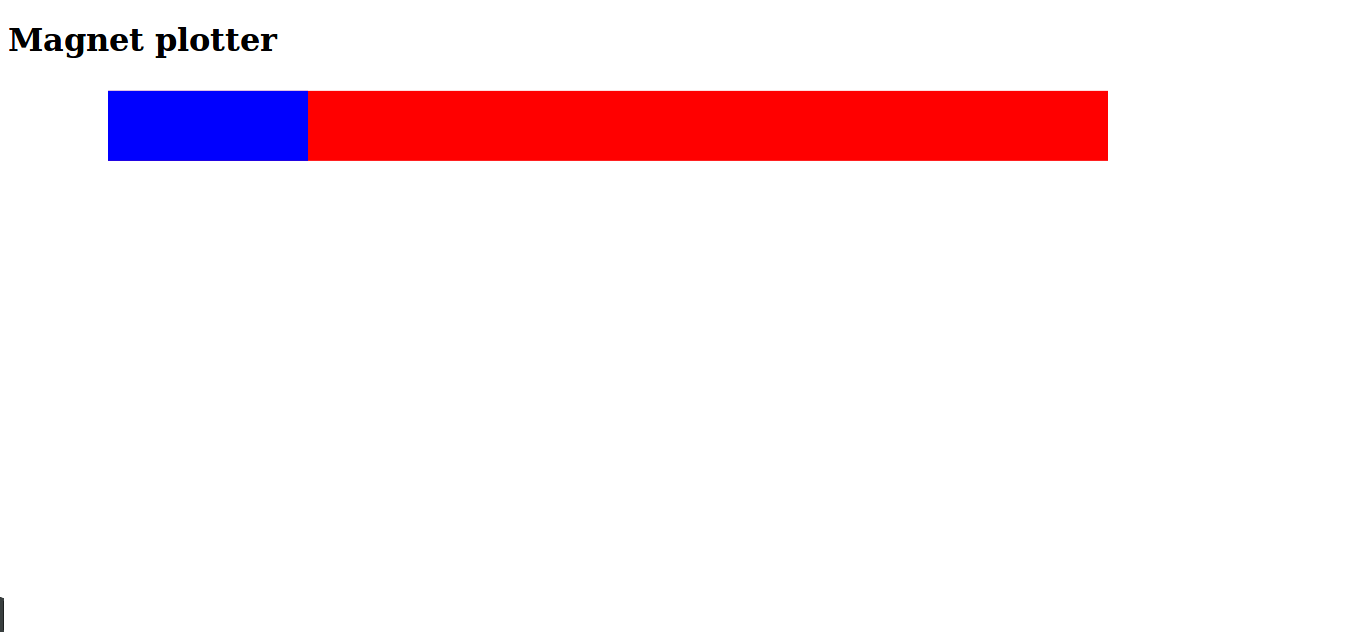
Here is the result of the program in the soft below.
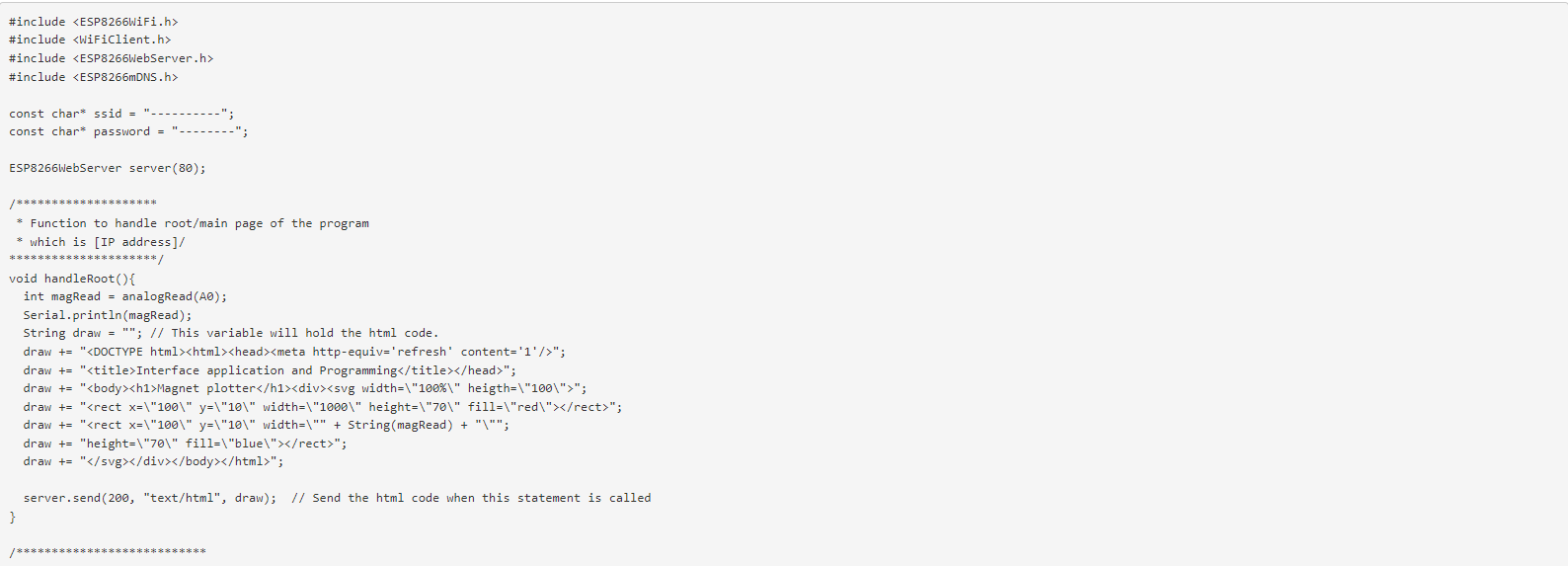
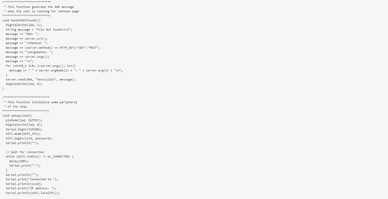
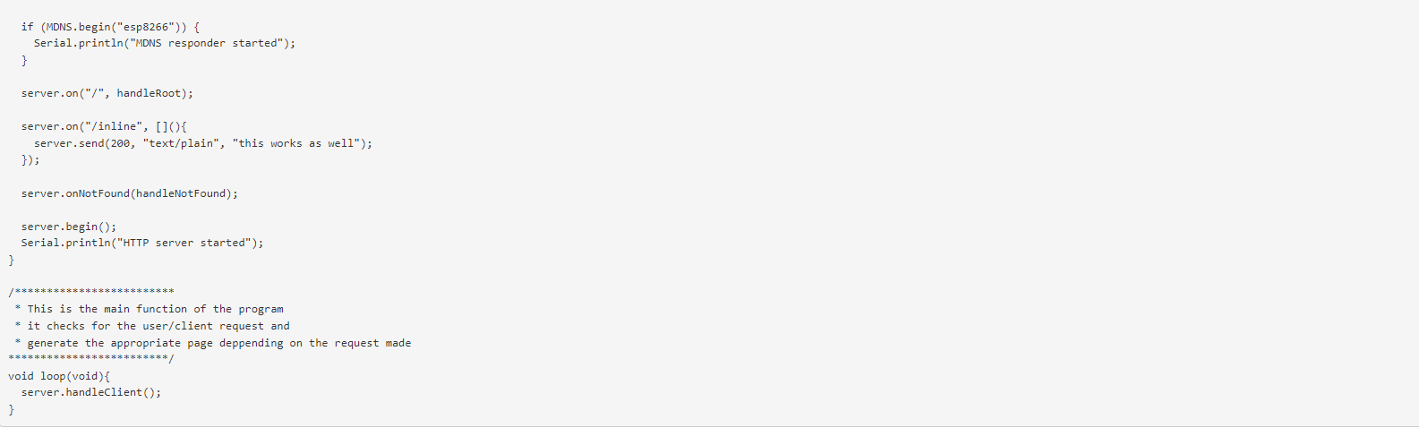
Programming board
Here below is the codes i used to program as shown in the images below
bellow is the video testing