INPUT DEVICE

Assignment
During this week Assignment, I designed a microcontroller board and added an input component, the LDR sensor. Now I am going to program the microcontroller to read the input data from the LDR and control the LED.
as all steps are going to be shown
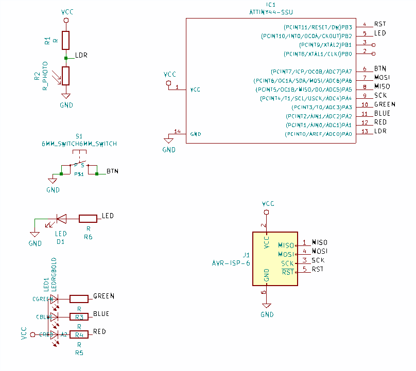
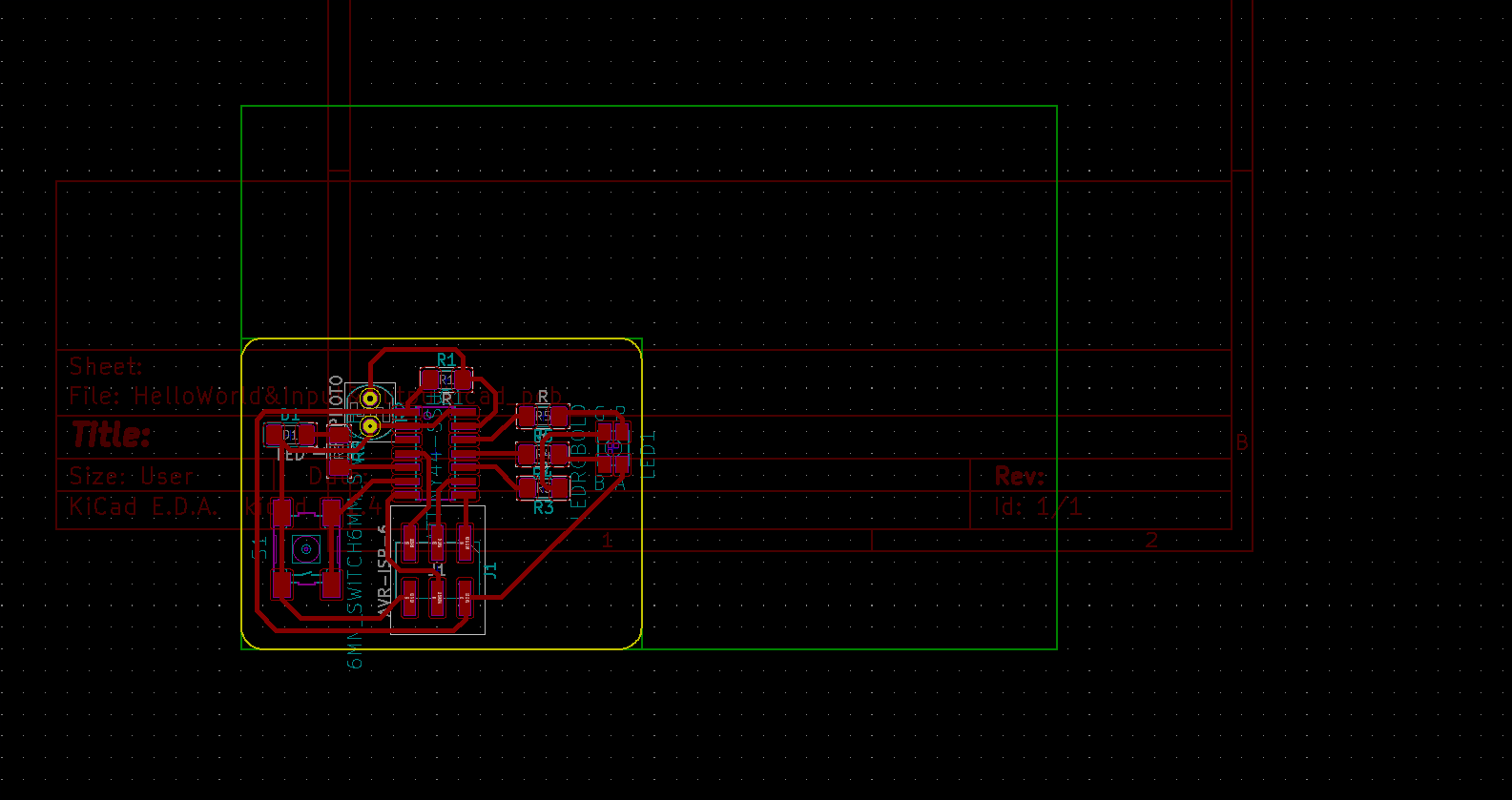
Using Kicad, I designed the board:
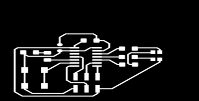
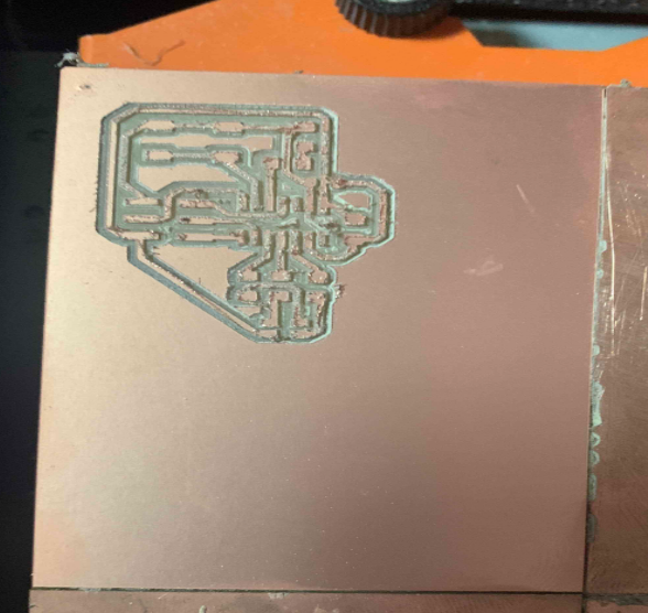
Here below is the image of traces
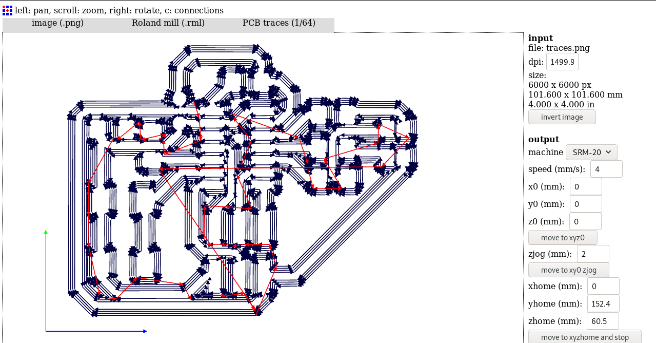
Importing the png image in fabmodules to generate the path and .rml file for the milling machine:
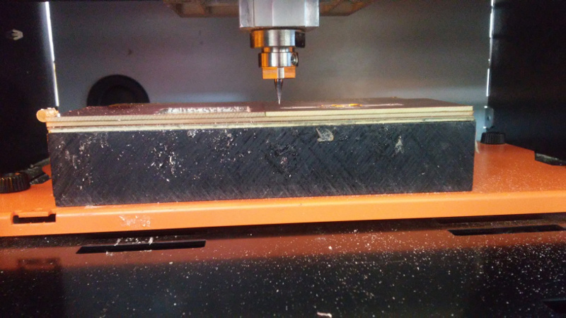
Milling the PCB :
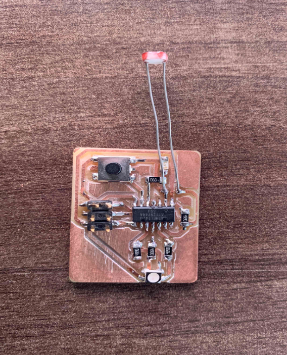
Here is the image after soldering the board:
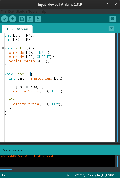
Here the next step wos to Programming the board as the codes used are shown in the image below:
Here below is the video