Computer controlled cutting
Work to be done:
# cut something on the vinylcutter
# design, lasercut, and document a parametric construction kit, accounting for the lasercutter kerf.
# group assignment: characterize your lasercutter's focus, power, speed, rate, kerf, joint clearance and types
Group Assignment:
If you want to explore our group Assignment Click below
Individual Assignment:
1.Design, lasercut, and document a parametric construction kit, accounting for the lasercutter width,which can be assembled in multiple ways
2.Cut something on the vinylcutter
INTRODUTION ON COMPUTER CONTROLLED CUTTING:
Computer-controlled cutting, also known as digital fabrication, is the process of using computer-controlled tools to cut or shape materials such as wood, metal, plastic, and paper. This technology has revolutionized the way we create products, allowing us to produce precise and complex designs with ease. The process typically involves creating a digital design using computer-aided design (CAD) software. The design is then sent to a computer-controlled cutting machine, such as a CNC router or laser cutter, which follows the design to cut or engrave the material. Computer-controlled cutting is used in a variety of industries, including manufacturing, architecture, fashion, and art. It allows for greater precision, speed, and efficiency compared to traditional methods of cutting and shaping materials by hand.
SAME PARTS OF LASER CUTTER
1.Laser source: This is the part of the machine that generates the laser beam. It typically consists of a gas, such as carbon dioxide, that is excited by an electrical charge to produce a high-powered laser.
2.Optics: The laser beam is directed and focused using a series of mirrors and lenses. The optics help to ensure that the laser is precisely focused on the material being cut or engraved.
3.Workbed: This is the platform on which the material being cut or engraved is placed. It is typically made of metal or another durable material and may be adjustable in height to accommodate different material thicknesses
4.Cutting head: This is the part of the machine that contains the laser and moves over the material to make cuts or engravings. It may be controlled by a computer program to create complex designs and shapes.
5.Exhaust system: Laser cutting produces fumes and smoke, so the machine typically includes an exhaust system to remove these byproducts from the cutting area.
6.Control panel: The control panel allows the user to set parameters such as the speed and power of the laser, as well as control the movement of the cutting head.
7.Cooling system: Laser cutting generates a significant amount of heat, so the machine typically includes a cooling system to prevent overheating and maintain the accuracy of the cutting process.
STEPS OF HOW LASER CUTTER WORKS
1.Design creation: The first step is to create a digital design using computer-aided design (CAD) software. The design can be created from scratch or imported from a file
2.Material preparation: The material to be cut or engraved is prepared and placed on the workbed of the laser cutter. The material must be able to withstand the heat and intensity of the laser beam.
3.Laser setup: The laser cutter is set up with the appropriate settings, such as laser power and cutting speed, based on the material being used.
4.Laser cutting: The laser cutter is activated, and the laser beam is directed and focused onto the material. As the laser moves over the material, it melts, vaporizes or burns away a thin layer, creating the desired cut or engraving.
5.Finished product: Once the cutting process is complete, the material is removed from the workbed, and any excess material is cleaned off.
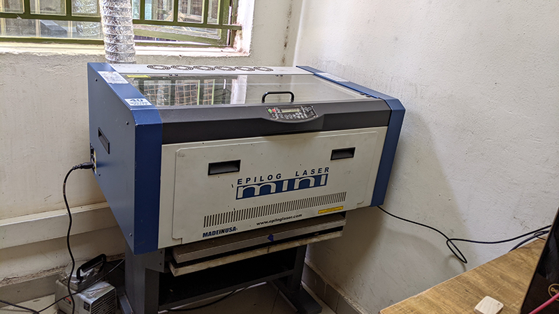
Here is the image of our laser cutter machine
Below is a link of more about our lasercutter or where u can shop laser cutter machine
- click here
- wikipedia website A parametric design is defined as a type of design process in which the relationships between various design elements are defined using parameters or variables. By changing the values of these parameters, the design can be easily modified and adjusted to meet different requirements or constraints. that the website i used in reseach!
- click here
- coreldraw community
A vinyl cutter
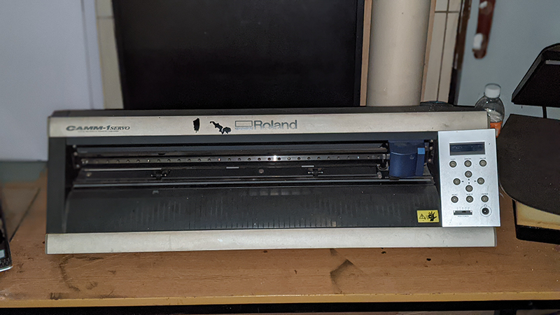
A vinyl cutter is a type of machine used to cut vinyl sheets or rolls into precise shapes and designs. It typically consists of a cutting blade that moves along the X and Y axes to cut the vinyl material according to the design inputted into the machine's software. Vinyl cutters are commonly used in the sign-making industry to create vinyl graphics for advertising and branding purposes.
Sammary About vinylcutter
A vinyl cutter is a machine used to cut vinyl material into precise shapes and designs. It typically consists of a cutting blade that moves along the X and Y axes to cut the vinyl material according to a digital design inputted into the machine's software. Vinyl cutters are commonly used in the sign-making industry to create vinyl graphics for advertising and branding purposes, but they can also be used for creating custom designs on t-shirts, stickers, and other items made from vinyl material. Vinyl cutters come in different sizes and capabilities, from small desktop models for personal use to larger industrial models for professional use. The most common types of vinyl cutters are those that use pressure and those that use a laser to cut the vinyl material. Overall, vinyl cutters are a useful tool for creating precise and intricate designs on vinyl material for a variety of applications.
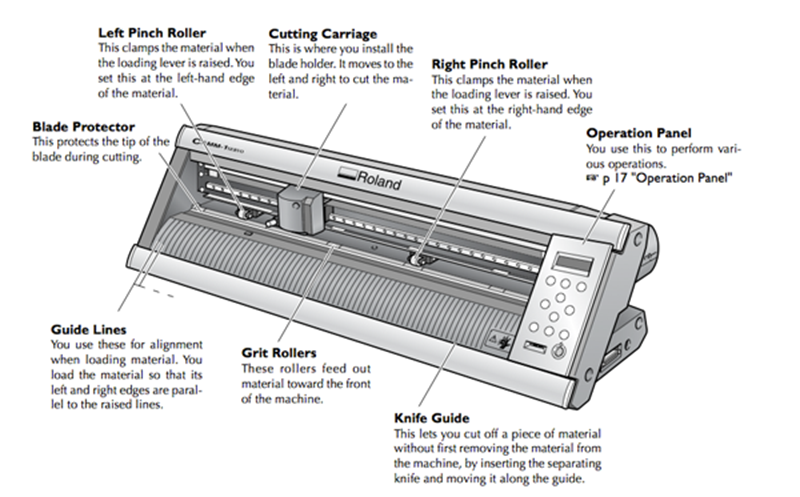
Main Parts Of vinylcutter
1.Cutting blade: The cutting blade is the main tool that is used to cut the vinyl material. It can be adjusted in terms of depth, speed, and pressure to achieve the desired cut.
2.Blade holder: The blade holder is a small component that holds the cutting blade in place and allows for it to move along the X and Y axes.
3.Cutting strip: The cutting strip is a thin piece of material that is placed underneath the vinyl material to protect the cutting surface and prolong the life of the cutting blade.
4.Rollers: Rollers are used to hold the vinyl material in place as it moves through the cutter. They also help to ensure that the vinyl material is properly aligned and stays in place during the cutting process.
5.Control panel: The control panel is where the user can set the cutting parameters such as the depth, speed, and pressure of the blade, as well as other settings.
6.USB and other connectivity ports: These ports allow the vinyl cutter to be connected to a computer or other devices for design transfer and communication.
7.Power switch: The power switch turns the vinyl cutter on and off.
8.Stand and base: The stand and base provide stability and support for the vinyl cutter, allowing it to be used safely and efficiently.
9.LCD display: Some vinyl cutters have an LCD display that provides information on the cutting process and settings.
How vinylcutter Works
1.Design creation: The first step is to create a digital design using vector software such as Adobe Illustrator, CorelDRAW, or Inkscape.
2.Design transfer: Once the design is complete, it is then transferred to the vinyl cutter software where it is processed and converted into a format that the vinyl cutter can understand.
3.Material preparation: The vinyl material is then loaded onto the vinyl cutter and secured in place using clamps or other fixtures.
4.Cutting parameters: The user sets the cutting parameters such as the depth, speed, and pressure of the blade according to the vinyl material being used and the complexity of the design.
5.Cutting process: Once the cutting parameters are set, the vinyl cutter uses its cutting blade to move along the X and Y axes, cutting the vinyl material into the desired shape and design.
6.Weeding: After the cutting is complete, the excess vinyl material is removed from the design using a process called weeding, leaving behind only the desired design on the vinyl material.
7.Transfer and application: The design is then transferred to the desired surface, such as a sign or a t-shirt, using transfer tape or other transfer methods.
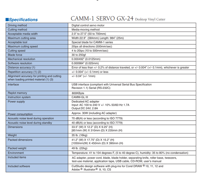
Here is the specification for vinylcutter
Individual Assignment : Designing a parametric press kit
Definition of Parametric design
According to
Parametric press-fit construction kit
A parametric press-fit is a method of joining two parts together by means of a tight, interference fit. In this technique, the size and shape of the mating features of the two parts are designed in a way that allows them to be pressed together with a controlled amount of force, creating a secure and permanent bond between them In a parametric press-fit, the dimensions of the parts are carefully calculated to ensure that the press-fit joint is strong enough to hold the parts together, but not so tight that the parts are damaged during assembly. The press-fit joint relies on the elasticity of the materials and the tightness of the fit to create a secure connection.
1.Setting the lasercutter's focus:
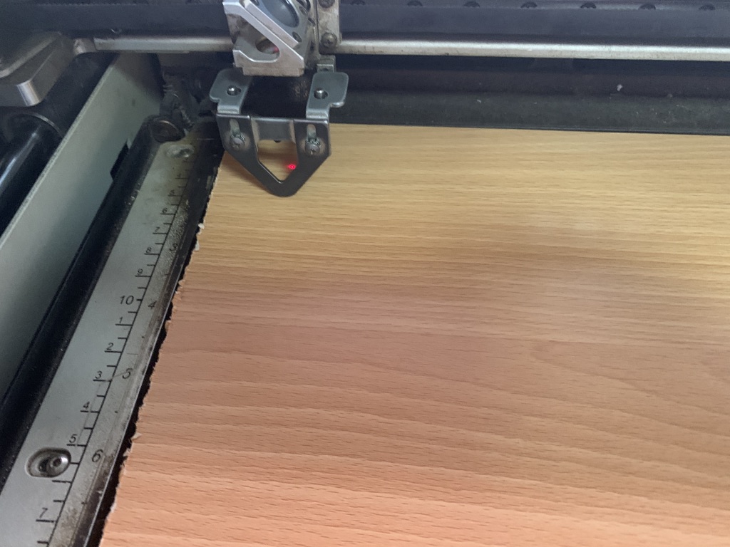
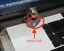
After turning on the machine and the air compressor/filter, we have to set the laser focus. This triangle tool help us set the laser focus as shown below.
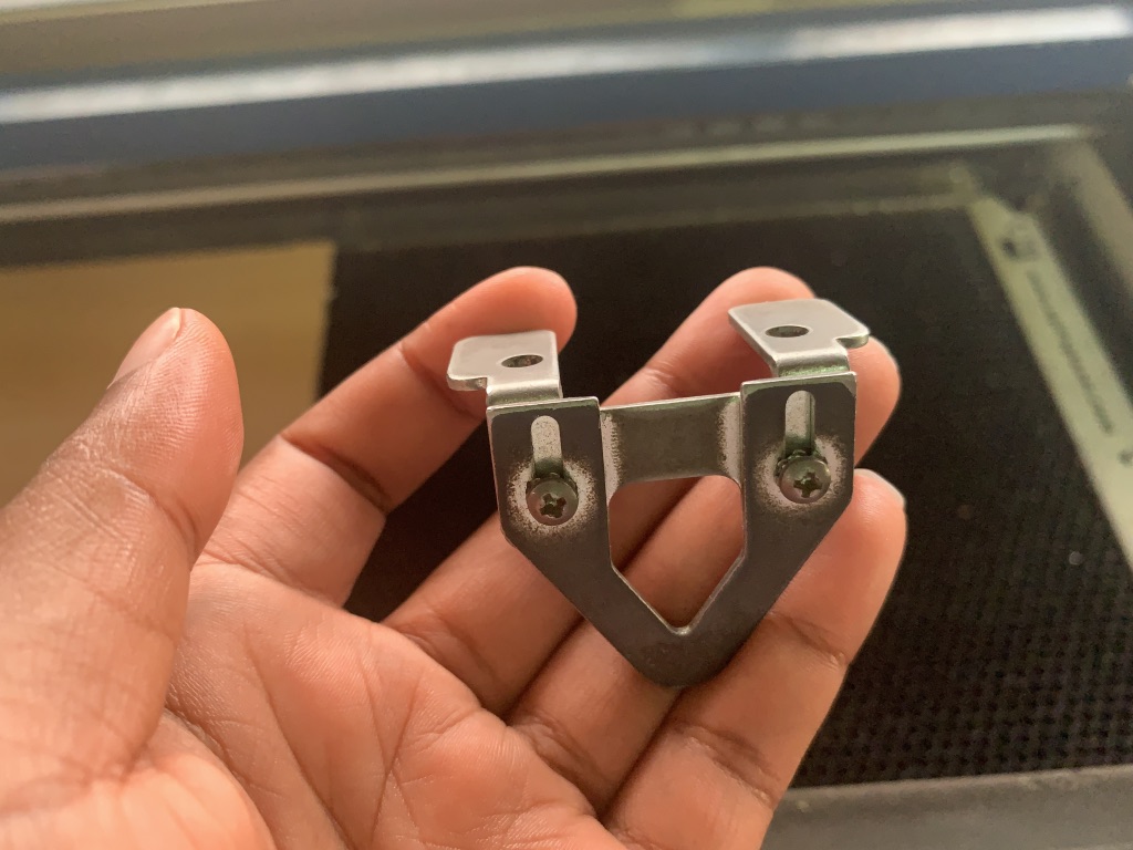
The key part of the laser system, is the control panel. Here you can control each axis of the machine while setting the laser focus. The purpose is to move the plane contanining the material in the z axis (up and down). Select focus in the menu and move the tray up and down until the laser is at a correct distance from the laser head. The correct distance is measured by hanging a small metallic tringle from the laser. Move the tray up, until the material touches the triangle, then remove the triangle - Finally press the joystick to set the focus.
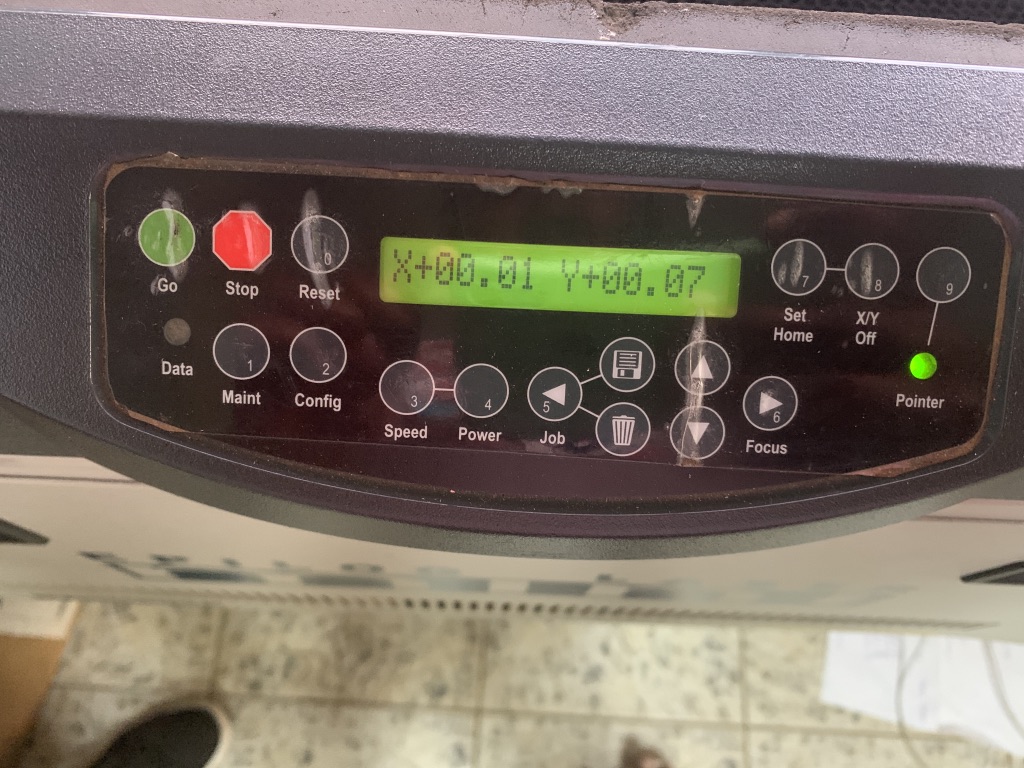
By pressing on Focus and on the up & down arrow, you can bring the required laser focus on the material as shown below:
2.Setting the lasercutter's power, speed, rate, kerf, and joint clearance :
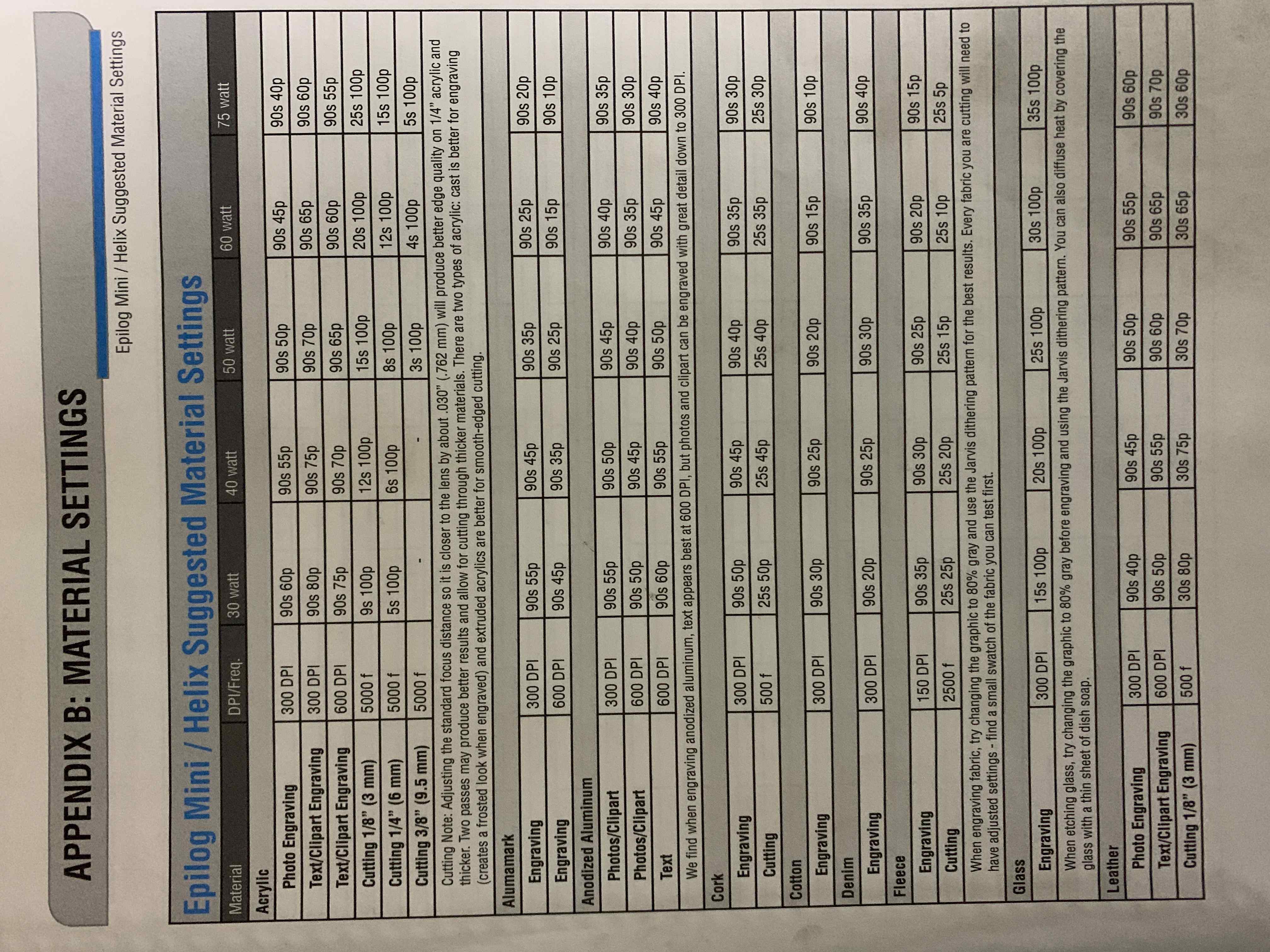
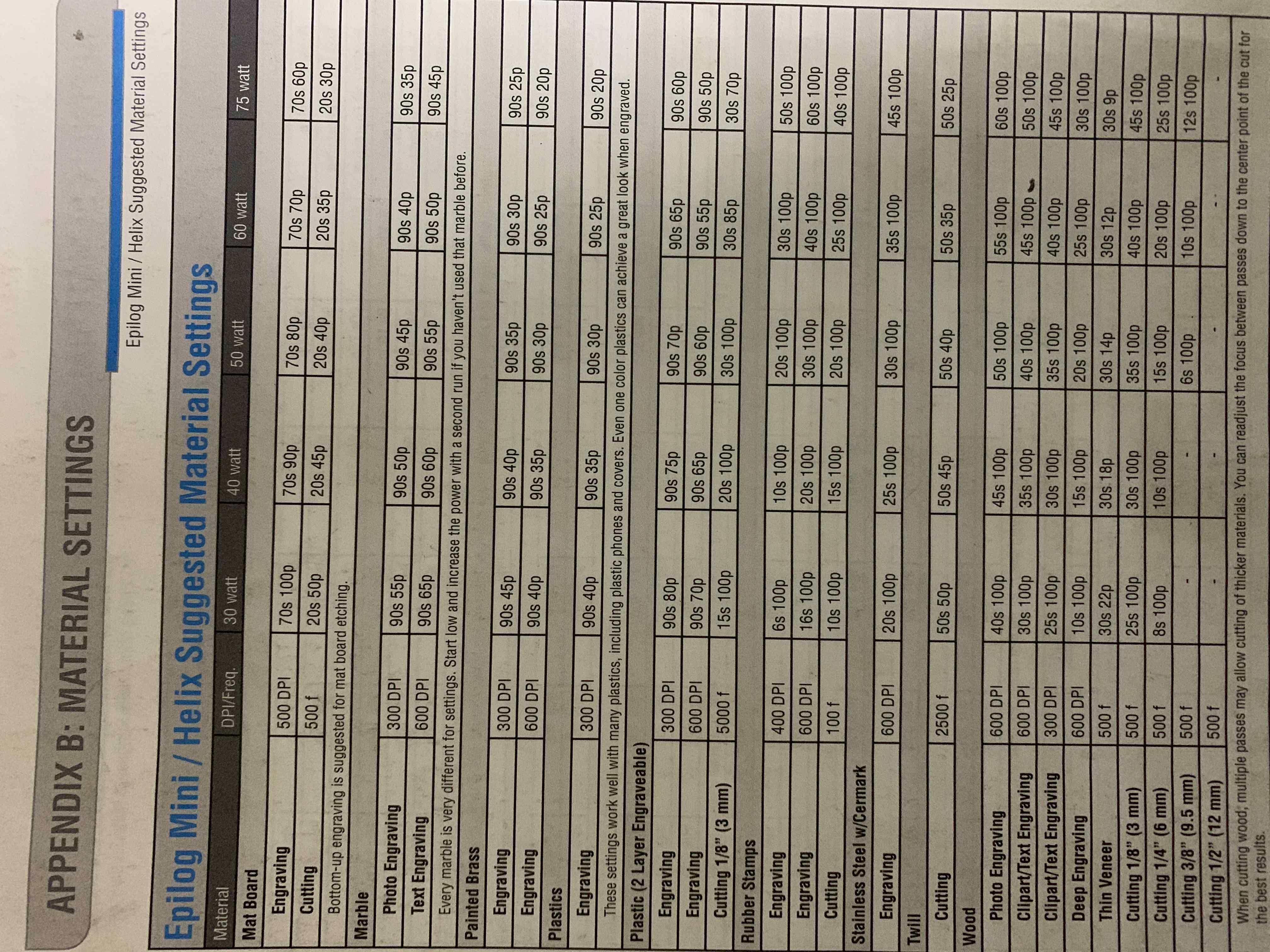
1. Power, Speed and rate: I used the lasercutter's manual to learn more about that. Each type of material has its correspondent power, speed and rate/frequency. I reffered to below info from the manual to set the preferences:
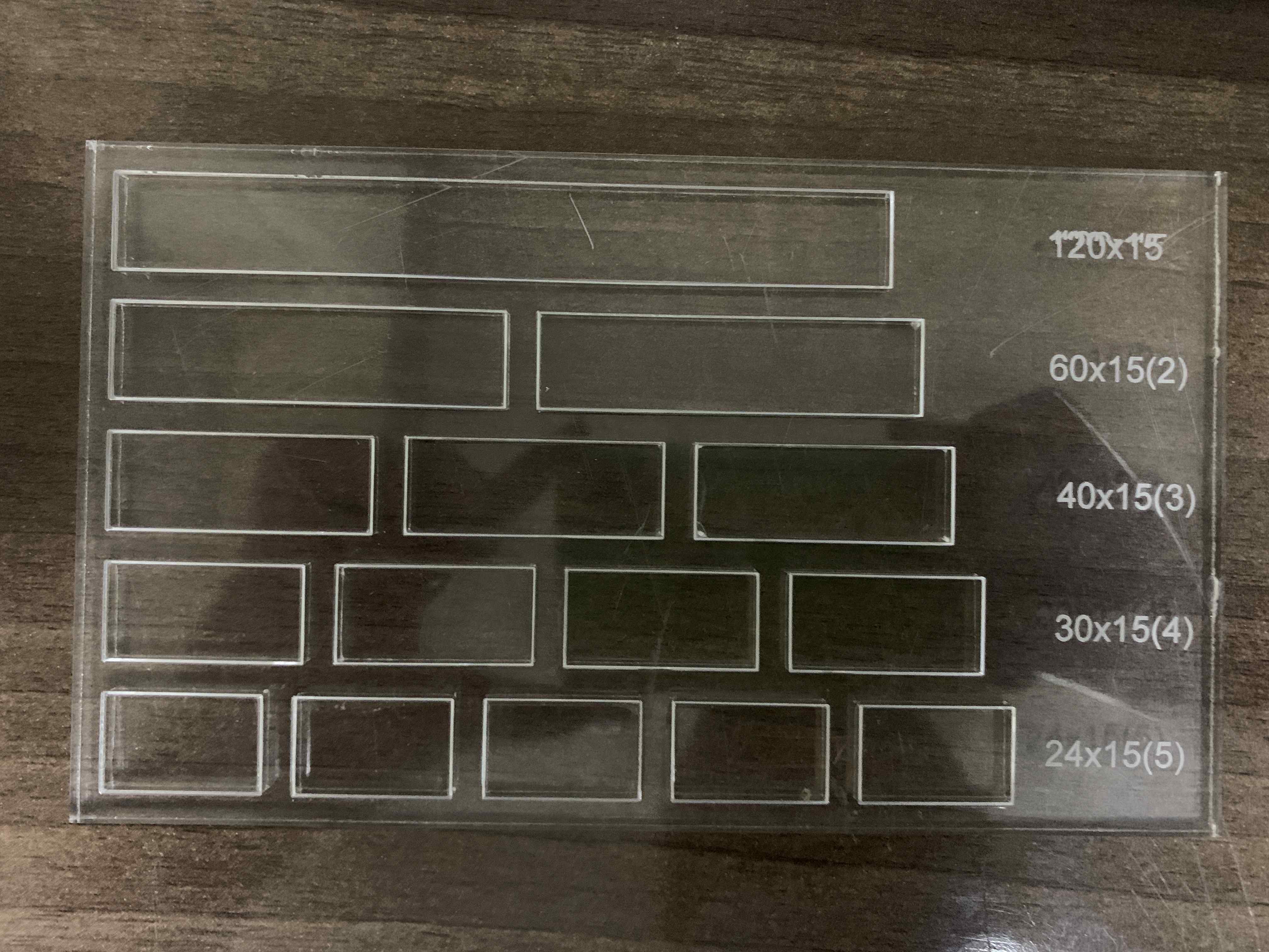
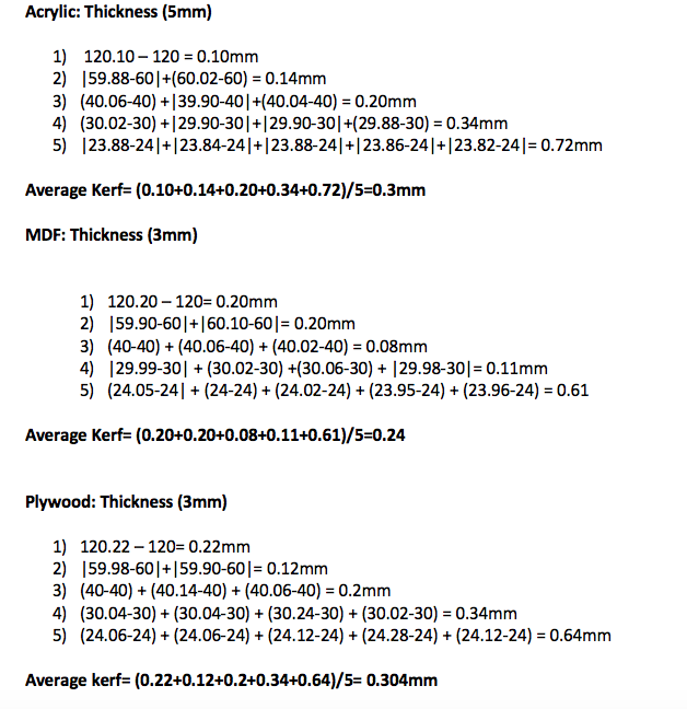
2. Kerf is the amount of material removed by the laser cutter as it burns through it. The kerf depends on the properties of the material, focal length, thickness and how the air is pushed out in the machine. I created a simple template that I can use on different materials to calculate the Kerf. The template is made of different rectangular shapes, with different lengths that I will meaure after cutting and compare with the actual lengths. I first cutted the tempalte design on Arcylic:
Second on MDF as shown in the image below:
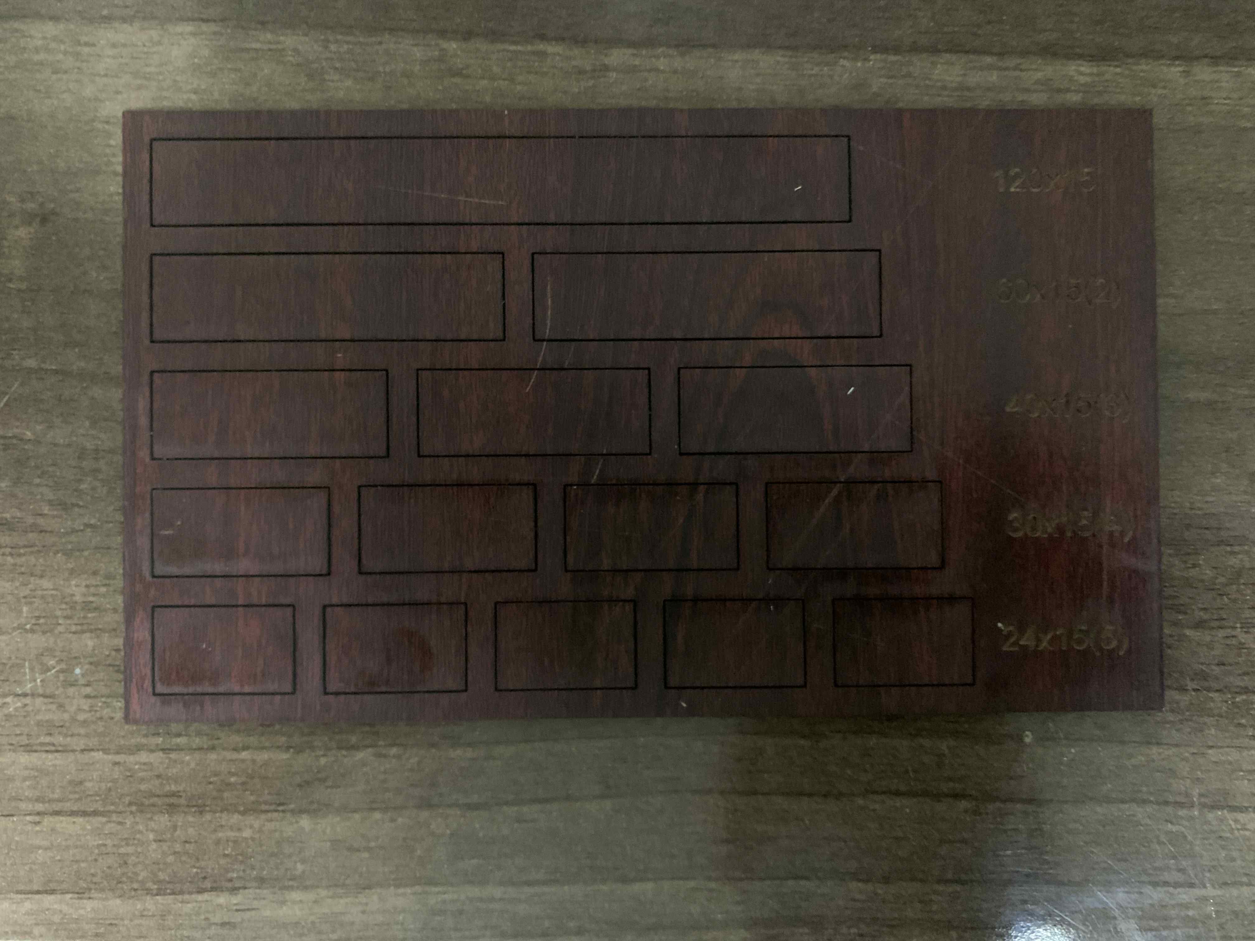
Third on Plywood as shown on the image below:
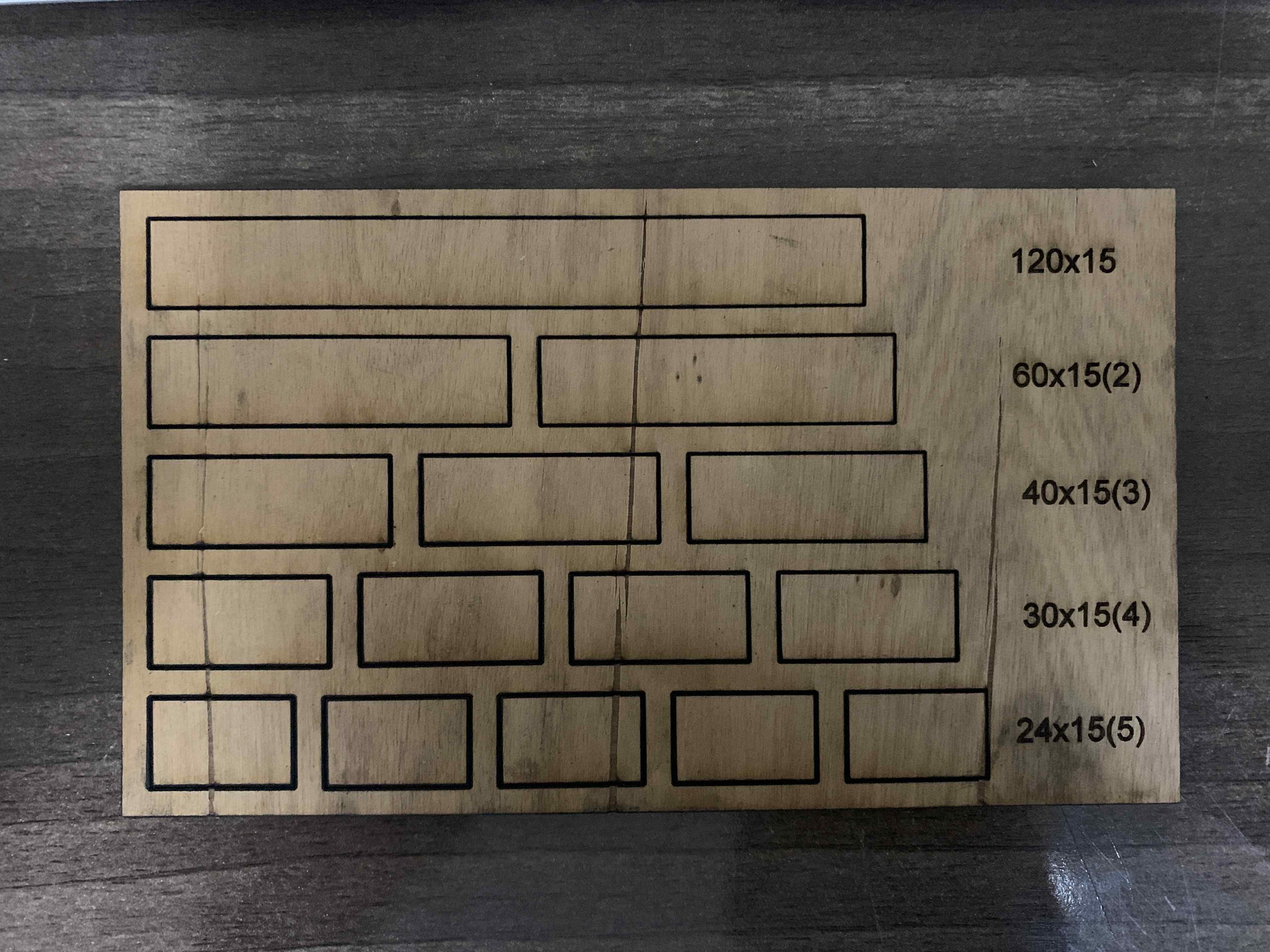
After that I used the vernier caliper to measure each single part that I cutted. Below are the results and how I calculated the kerf from different types of the material as shown in the image below:
process:
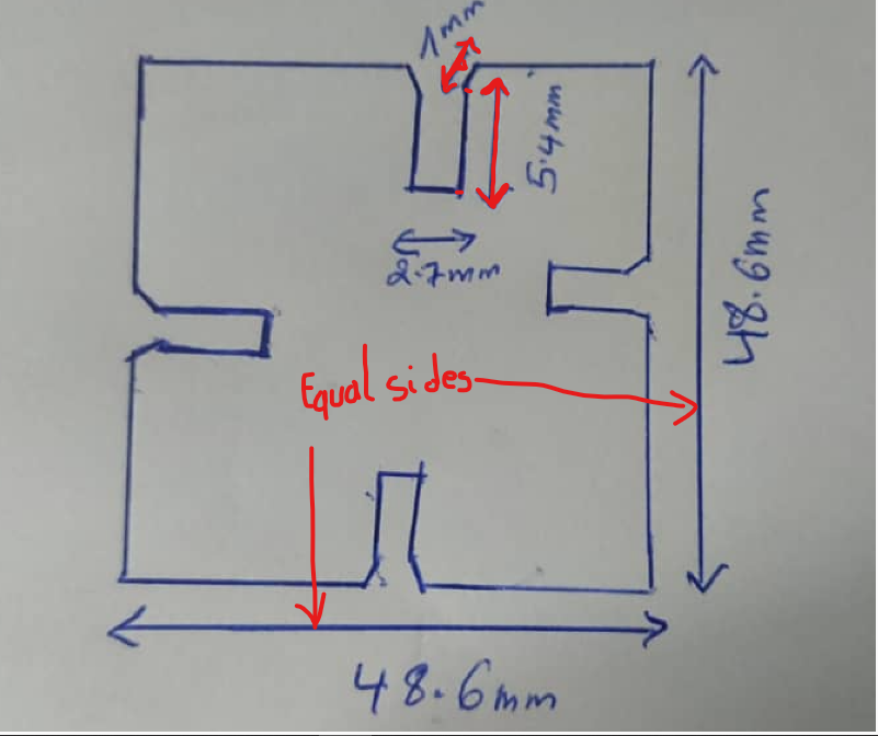
Before i draw my Work on a paper before using computer software as shown in the following image
Next step is to design in solidwork software
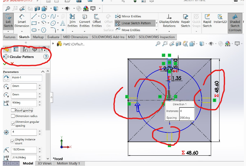
Here is the images of step by steps of how i design my work in solidworks I have created circular rectangle in the centre line
1.Designing circular lines
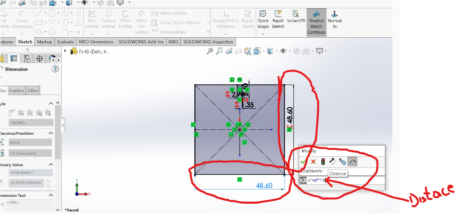
2.Setting dimensionong outside of rectangular
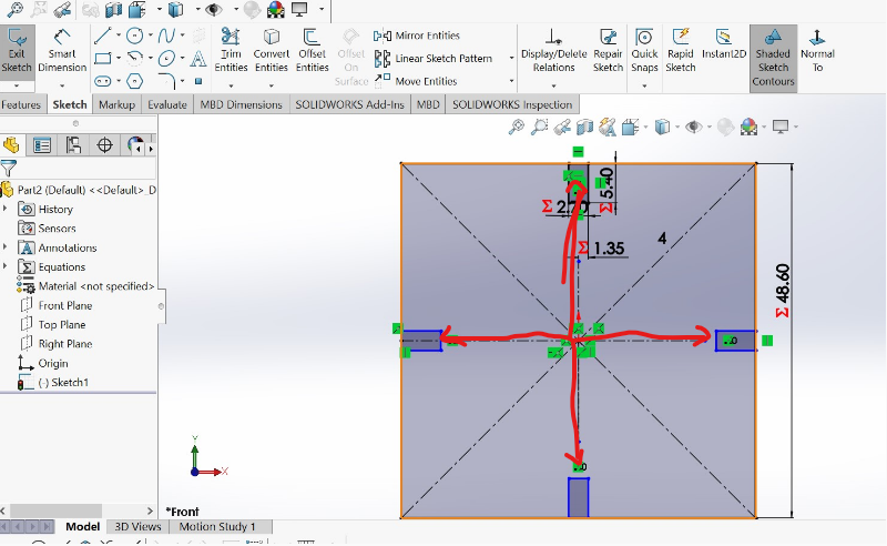
3.Setting and cealling equal rectangles in all corners to create same and equal edges
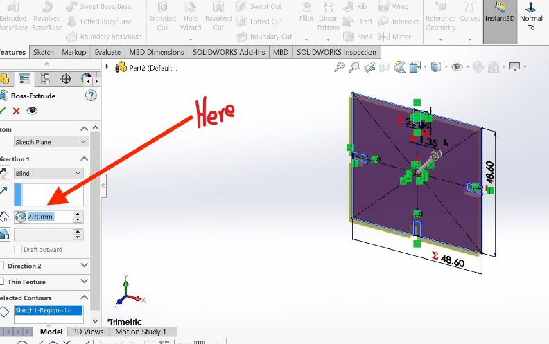
4.Setting and Extruding the base by 2.7mm according to your design
5.Setting and creating chamfer of 1mm on all edges according to my design
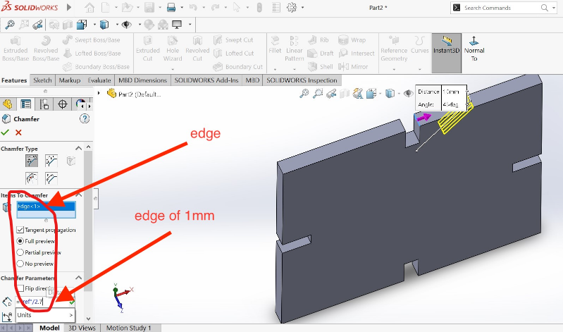
6.Here is the image to show how the edges looks after being created
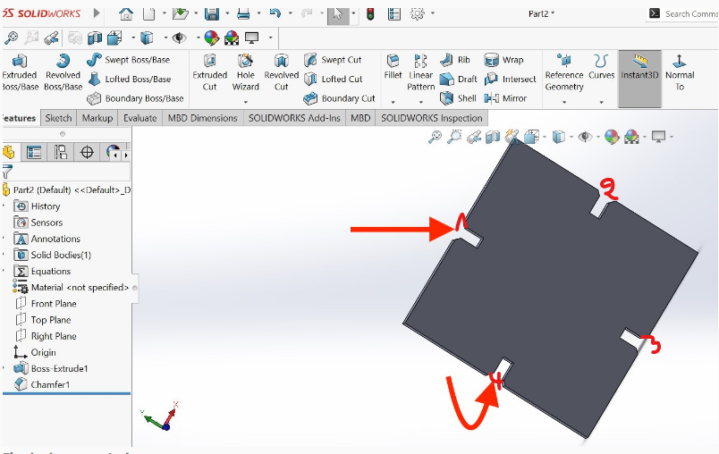
7.Creating and design measurements on my work looks like this
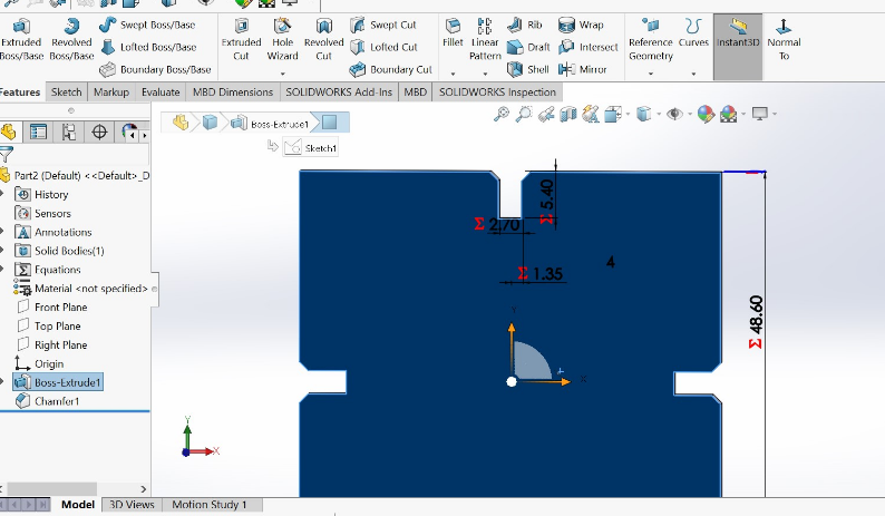
8.By using the ref as global variable to be references to others measurable entiries
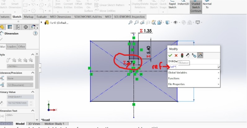
9.Setting the Parametric design for all measurements of my work
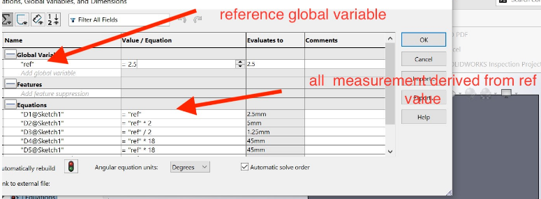
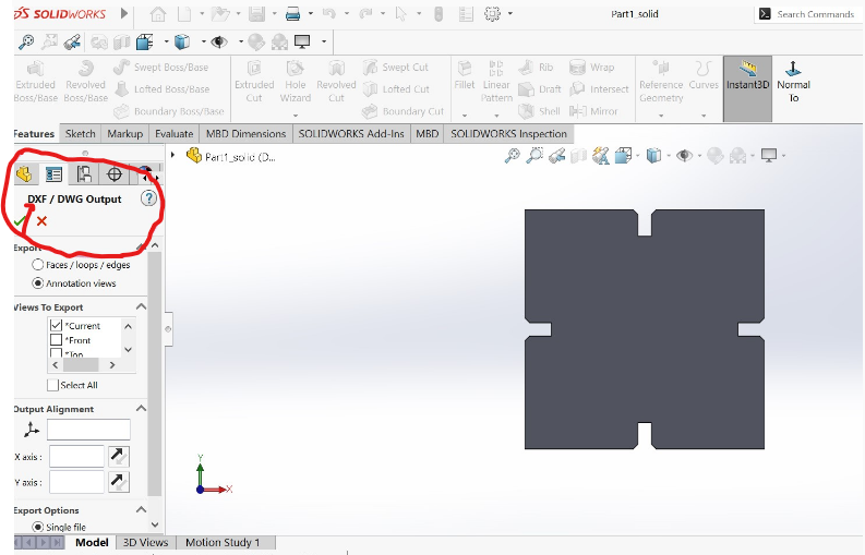
10.Here are the process of Saving design in dxf format to be used in CorelDRAW
The next step is using CorelDRAW software
I use CorelDRAW in order to make vectors to be followed by laser cutter while cutting , we have to use coredraw. but there is other software that can be used like inkscape
Here is the link for the tips for coredraw and laser engravings
1.Open coredraw software on my computer
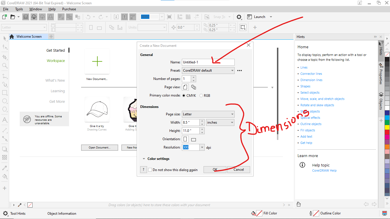
2.Creating warkplace in coreldraw
3.This image shows the open, import, export, save, save as... used in coreldraw
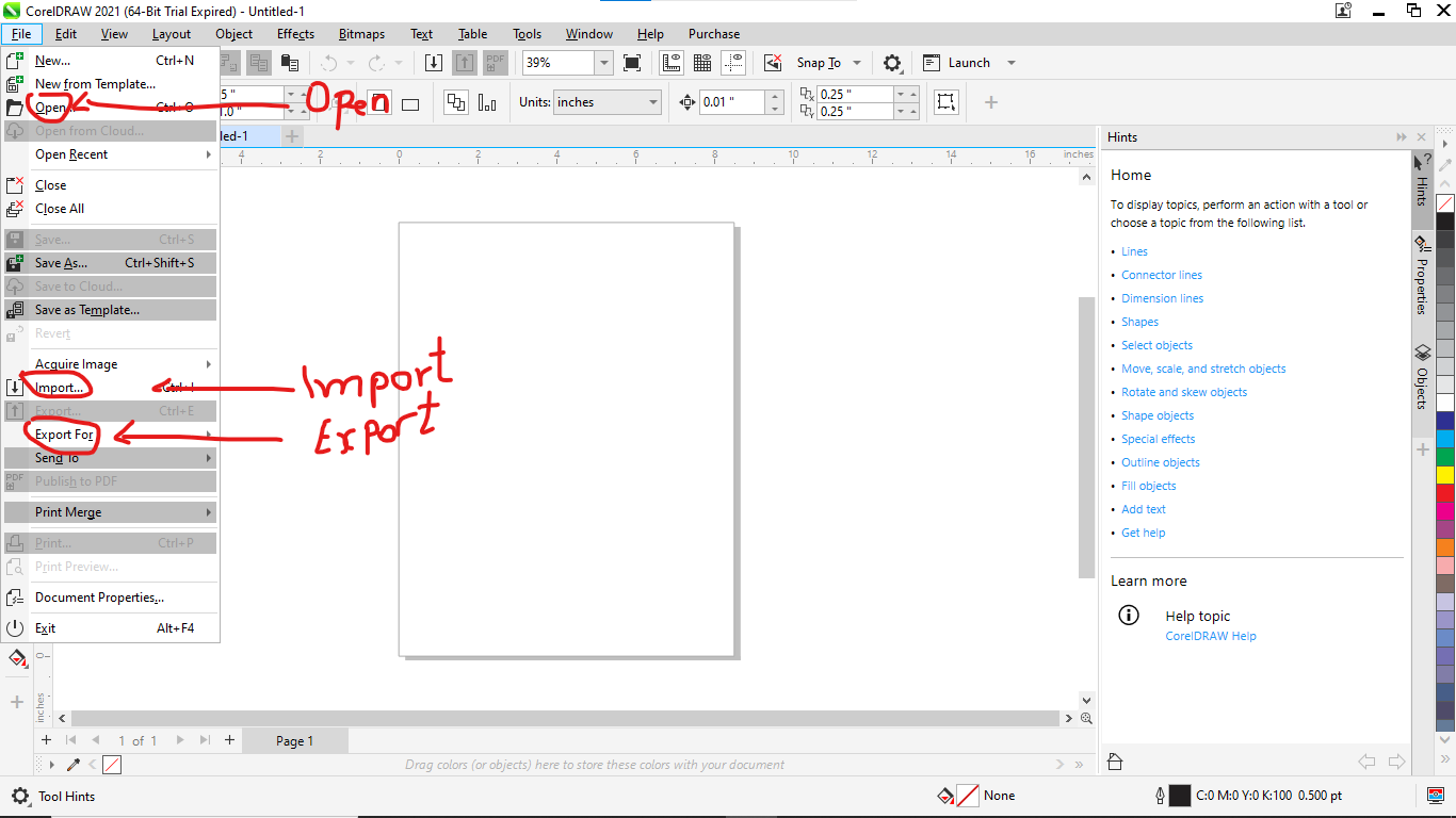
Here on this part i choise to copy and paste DXF fille in coreldraw as i saved dxf fille before exporting my work in solidwork
DXF: is a file format used for exchanging CAD (Computer-Aided Design) data between software programs. The DXF file format is developed by Autodesk and stands for Drawing eXchange Format. It is a vector image format used to represent 2D and 3D designs and models.
4.On this stage i import my work in coredraw interface as shown in the image below
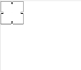
5.Using Hairline in coreDraw
Using hairlines in CorelDRAW can be useful for creating very fine and precise lines, especially when designing for print or engraving. A hairline is a line with a width of 0.003 mm (or 0.0001 inch), which is the smallest possible line width that can be printed or engraved according to coreldraw cummunity.
Below more about:
6.The image below shows my hairlines in coreldraw

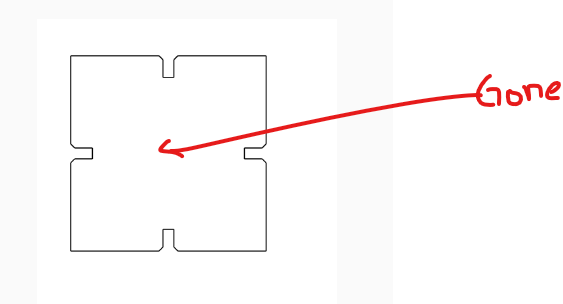
7.Before and after removing Unwanted lines found in dxf image
Before removing unwanted lines
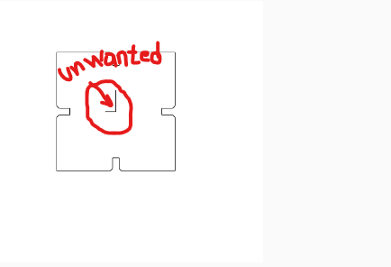
After removing unwanted lines
Here is assembly of laser cutting object in multiple way and The full explaination:
1.Different assembly techniques of laser cutting are:
1.Interlocking Joints: Laser-cut parts can be designed with interlocking features that fit together like puzzle pieces. These joints can provide stability and strength to the assembly without the need for additional fasteners or adhesives. Examples of interlocking joints include tabs, slots, or dovetail joints.
2.Varied configurations: This suggests showcasing the object's assembly in different arrangements or configurations. For example, if the object consists of modular components, you could demonstrate different ways of combining those modules to create unique shapes or structures.
3.Assembly variations for similar objects: If you have multiple laser-cut objects that are similar in design but differ in certain aspects, you can showcase the assembly process for each object, highlighting the specific variations. This can help illustrate how different design choices or modifications affect the assembly procedure
2.Varied configurations of laser cutter machine:
1.Laser Cutter Bed Size: Laser cutter machines come in various sizes, with different bed dimensions. The bed size determines the maximum work area or the size of the material that can be accommodated. Some machines have small bed sizes suitable for hobbyists or small-scale projects, while others have large industrial-sized beds for handling larger materials or mass production.
2.Laser Types: Laser cutter machines can be equipped with different types of lasers, such as CO2 lasers, fiber lasers, or diode lasers. Each type of laser has its own advantages and applications. For example, CO2 lasers are commonly used for cutting and engraving materials like wood, acrylic, and fabric, while fiber lasers are more suitable for metal cutting and marking.
3.Power Output: Laser cutter machines have varying power outputs, usually measured in watts. Higher power output allows for faster cutting speeds and the ability to cut through thicker or denser materials. The power output required depends on the materials you plan to work with and the desired cutting efficiency.
4.Control Systems: Laser cutter machines can have different control systems, ranging from basic manual control to advanced computer numerical control (CNC) systems. CNC systems offer precise control over the laser cutting process, allowing for complex designs and automation. They often come with software that enables design creation, import, and precise control of cutting parameters.
5.Additional Features: Laser cutter machines may have additional features to enhance functionality and versatility. These can include autofocus systems, rotary attachments for cylindrical objects, honeycomb or slat beds for supporting materials, air assist systems for improved cutting quality, and exhaust systems for fume extraction.
Assembly variations for similar objects of laser cutter machine:
1.Modular Design: Instead of creating a single laser-cut object, you can design a modular system where multiple laser-cut components can be assembled in various configurations. By using interchangeable or connectable parts, you can create different arrangements or structures using the same basic components. This allows for flexibility and customization.
2.Variable Dimensions: You can create similar laser-cut objects with variations in their dimensions. For example, if you're creating a box or enclosure, you can adjust the dimensions to create objects of different sizes. This variation in size can change the overall functionality or purpose of the objects.
3.Customizable Features: Incorporating customizable features in the laser-cut objects allows for assembly variations. For instance, you can design objects with adjustable or interchangeable parts that can be personalized or tailored to specific needs. This could include adjustable shelves, interchangeable panels, or configurable compartments.
4.Swappable Components: Designing laser-cut objects with swappable components offers assembly variations. You can create objects where certain parts can be easily replaced or interchanged, altering the functionality or appearance of the object. This could involve interchangeable decorative elements, functional attachments, or different configurations of moving parts.
5.Reconfigurable Joints: By incorporating reconfigurable joints or connectors, laser-cut objects can be assembled in multiple ways. These joints may allow for different angles, orientations, or connections between parts. This flexibility enables users to experiment with different assembly arrangements, creating unique configurations.
Assembly variations for similar objects of laser cutter machine are :
1.Interchangeable Parts: Design the objects with certain components or sections that can be easily swapped or interchanged. This allows for different configurations or combinations of parts, providing versatility in the assembly process. Users can choose from a set of interchangeable pieces to customize the final object according to their preferences or needs.
2.Variable Arrangements: Create laser-cut objects that can be assembled in multiple arrangements or orientations. This can be achieved by incorporating reversible or symmetrical design elements. By assembling the parts in different ways, users can achieve various appearances or functionalities without changing the individual components.
3.Adjustable Features: Include adjustable or movable components in the design. These features can allow users to modify the size, shape, or position of certain parts, resulting in different assembly variations. For example, a laser-cut table design could have adjustable legs or extendable sections that enable different configurations.
4.Modular Systems: Develop a modular system where multiple laser-cut objects can be combined or interconnected. Each individual piece can serve a specific function, and users can assemble them in different combinations to create unique configurations or structures. This approach offers flexibility and adaptability for various purposes or settings.
5.Add-On Attachments: Design laser-cut objects with attachment points or slots that accommodate add-on components. These attachments can expand the functionality or enhance the appearance of the base object. Users can choose from a range of compatible add-ons and assemble them in different ways to achieve desired variations.
8.Next step is selecting apropriate laser cutter in the list as shown on the image below
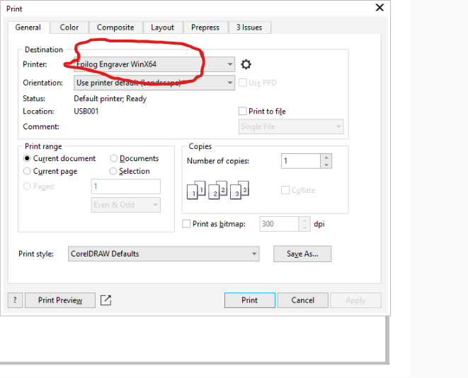
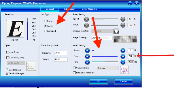
9.Setting parameters like power, speed and job type(raster,vector or both). we hve selected vector because it is a vector image
10.Checking and modifying properties for laser cutter to perform my work well
11.On this stage it's time for our machine to start doing my work

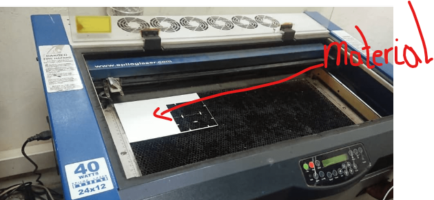
12.Here i place the material in the machine as shown in the image below
13.Setting focus of the laser using focus tool
14.My command is that the laser will cut ten equal parts of my parametric as shown in the image below after cutting
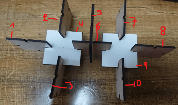
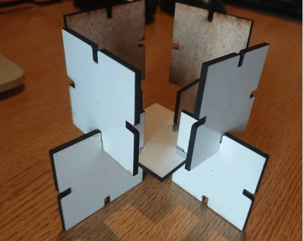
After cutting my work and assembled
Vinyl Cutting
The vinylcutter available at fablab Rwanda is Roland DG CAMM-1 GS-24. The vinylcutter Roland DG CAMM-1 GS-24 is precision and efficiency to the max. With a completely redesigned cutting carriage and blade holder, the GS-24 offers great stability, up to 10x overlap cutting and down force of up to 350 grams so that you can cut like never before — even on thick, dense substrates. The GS-24 is Roland DG's best desktop cutter ever.
Here below is the image of our vinylcutter Roland DG CAMM-1 GS-24

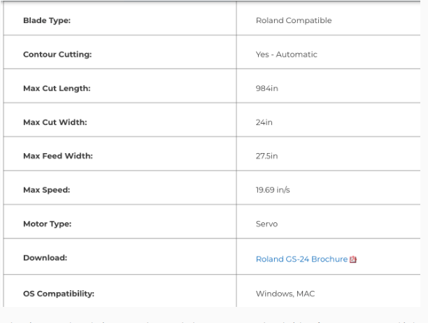
Here are the specification of Roland DG CAMM-1 GS-24. as shown in the image below
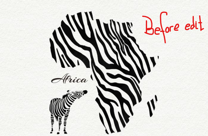
Here in vinylcutter i download a vector that i need to edit and cut. so that it will be easy for me to import in the cut studio
The image below shows my downloads how it looks before editing in cut studio.
Here i import it in cut studio and i start editing
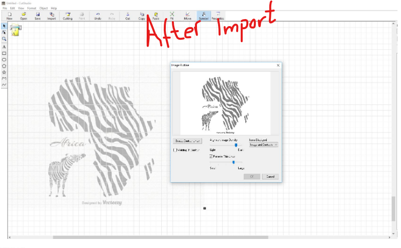
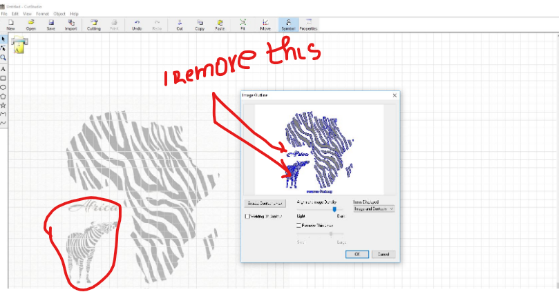
Here on the next step i delete unwanted parts
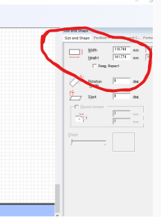
On this stage next i was sizing image to be cutted with sizing tool as shown below
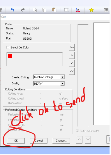
Now next thing was to send my command to vinylcutter in the following setting
After sending my command to vinylcutter it's my time i go to my vinylcutter for the setting before strating the work
The first thing is to place the vinyl sheet in the vinyl cutter and position sensors in between the area where the cutter have to use . so do that you press enter button and the machine show you the size of selected length
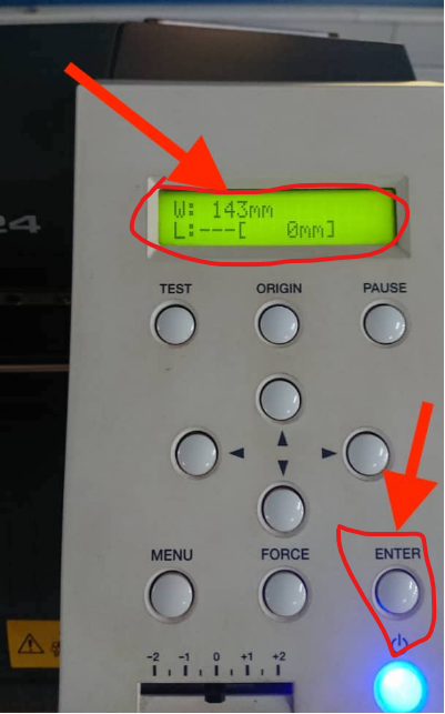
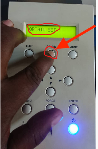
Then before printing , we have to set the reference or origin or your cutting. you just use arrow keys for cutting head positioning and then you press on origin button and then you get the message saying that the origin is set.
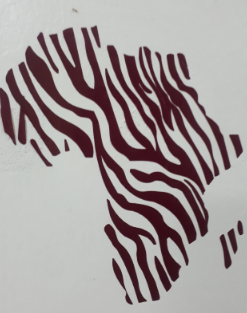
Results:After cutting, i got a logo shape and i used it as a sticker on the wall decolation as shown below
