13. Networking and communications
This week's assignment was to understand networking and communication between multiple electronic devices. The wireless and wired networking have different ways and terms to understand at first.
Wired Networking
As we all know, “wired” refers to any physical medium made up of cables. Copper wire, twisted pair, or fiber optic cables are all options. A wired network employs wires to link devices to the Internet or another network, such as laptops or desktop PCs.Wireless Networking
“Wireless” means without wire, media that is made up of electromagnetic waves (EM Waves) or infrared waves. Antennas or sensors will be present on all wireless devices. Cellular phones, wireless sensors, TV remotes, satellite disc receivers, and laptops with WLAN cards are all examples of wireless devices. For data or voice communication, a wireless network uses radiofrequency waves rather than wires.What is a protocol?
Protocol is a system of rules that allow two or more entities of a communications system to transmit information via any kind of variation of a physical quantity.Types of communication protocols
There are different types of data transfer available in the digital electronics such as serial communication and parallel communication. Similarly the protocols are divided into two types such as Serial Communication Protocol and Parallel Communication Protocols. Examples of Parallel Communication Protocols are ISA, ATA, SCSI, PCI and IEEE-488. Similarly there are several examples of Serial Communication Protocols such as CAN, ETHERNET, I2C, SPI, RS232, USB, 1-Wire, and SATA etc.
Clock Synchronization
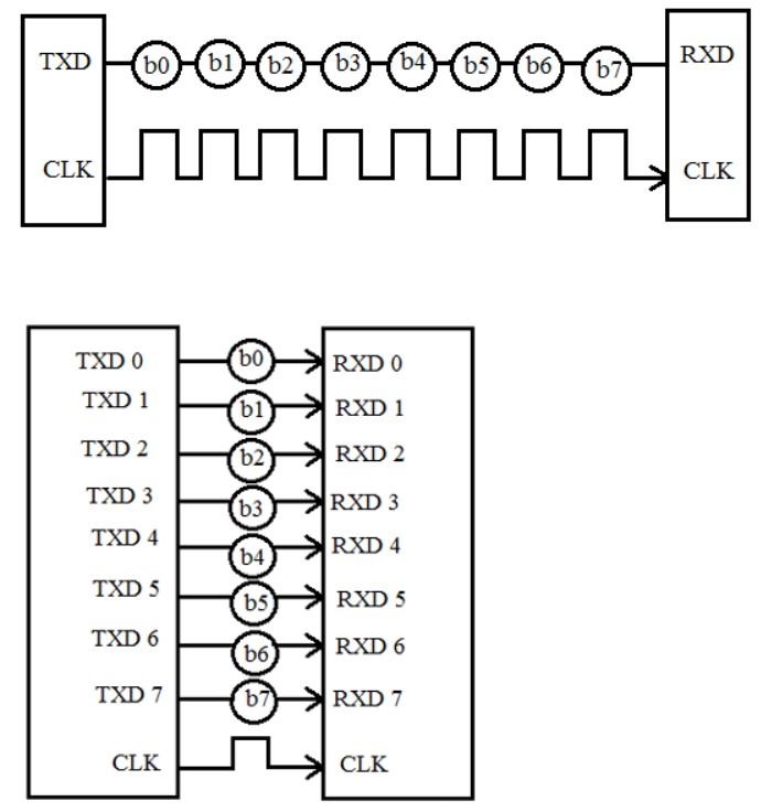
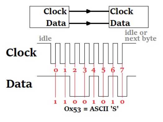
The clock is different for serial devices and it is classified in two type viz. Synchronous Serial Interface and Asynchronous Serial Interface.Synchronous Serial Interface:
It is a point-to-point connection from a master to slave. In this type of interface, all the devices use single CPU bus to share data and clock. The data transmission becomes faster with same bus to share clock and data. Also there is no mismatch in baud rate in this interface. In transmitter side, there is a shift of the data onto serial line providing the clock as a separate signal as there is no start, stop and parity bits are added to data. In receiver side, the data is being extract using the clock provided by the transmitter and converts the serial data back to the parallel form. The well-known examples are I2C and SPI.
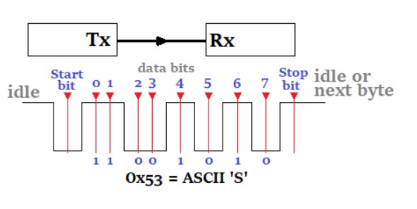
Asynchronous Serial Interface:
In asynchronous Serial Interface, the external clock signal is absent. The Asynchronous Serial Interfaces can be seen in mostly in long distance applications and are a perfect fit for the stable communication. In asynchronous Serial Interface the absence of external Clock Source makes it rely on several parameters such as Data Flow Control, Error Control, Baud Rate Control, Transmission Control and Reception Control. On the transmitter side, there is a shifting of parallel data onto the serial line using its own clock. Also it adds the start, stop and parity check bits. On the receiver side, the receiver extracts the data using its own clock and convert the serial data back to the parallel form after stripping off the start, stop, and parity bits. The well-known examples are RS-232, RS-422 and RS-485.
Synchronous Serial Communication Protocols
SPI Protocol
The Serial Peripheral Interface (SPI) is a synchronous interface which allows several SPI microcontrollers to be interconnected. In SPI, separate wires are required for data and clock line. Also the clock is not included in the data stream and must be furnished as a separate signal. The SPI may be configured either as master or as a slave. The four basic SPI signals (MISO, MOSI, SCK and SS), Vcc and Ground are the part of data communication. So it needs 6 wires to send and receive data from slave or master. Theoretically, the SPI can have unlimited number of slaves. The data communication is configured in SPI registers. The SPI can deliver up to 10Mbps of speed and is ideal for high speed data communication.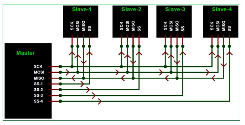
I2C Serial Communication
Inter integrated circuit (I2C) two-line communication between different ICs or modules where two lines are SDA (Serial Data Line) and SCL (Serial Clock Line). Both the lines must be connected to a positive supply using a pull up resistor. I2C can deliver speed up to 400Kbps and it uses 10 bit or 7 bit addressing system to target a specific device on the i2c bus so it can connect up to 1024 devices. It has limited length communication and is ideal for onboard communication. I2C networks are easy to setup since it uses only two wires and new devices can simply be connected to the two common I2C bus lines. Same like SPI, microcontroller generally have I2C pins to connect any I2C device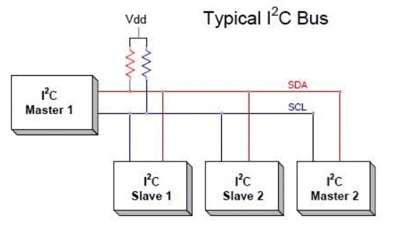
CAN Communication
CAN bus is an inexpensive, robust vehicle bus standard designed for multiple CAN device communications with one another without a host computer. CAN is also called as multi-master serial bus and the CAN devices on bus are referred to as nodes. Two or more nodes are required on the CAN network to communicate. All nodes are connected to each other via a two wire bus (CAN H and CAN L) and the wires are 120ohms nominal twisted pairs. Termination resistor commonly 120 ohms is must in each node in order to suppress the reflections as well as return the bus to its recessive or idle state.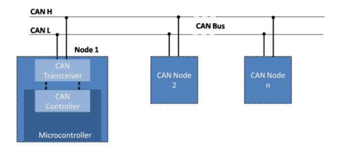
Asynchronous Serial Communication Protocols
RS232
The RS232 (Recommended Standard 232) is very common protocol used to connect different peripherals such as Monitors, CNCs etc. The RS232 comes in male and female connectors. The RS232 is point-to-point topology with maximum one device connected and covers distance up to 15 meters at 9600 bps. Information on the RS-232 interface is transmitted digitally by logical 0 and 1. The logical "1" (MARK) corresponds to a voltage in the range from -3 to -15 V. The logical "0" (SPACE) corresponds to a voltage in the range from +3 to +15 V. It comes in DB9 connector which has 9 pinouts such as TxD, RxD, RTS, CTS, DTR, DSR, DCD, GND.RS422
The RS422 is similar to RS232 which allows to simultaneously send and receive messages on separate lines but uses a differential signal for this. In the RS-422 network, there can only be one transmitting device and up to 10 receiving devices. The data transfer speed in RS-422 depends on the distance and can vary from 10 kbps (1200 meters) to 10 Mbps (10 meters). The RS-422 line is 4 wires for data transmission (2 twisted wires for transmission and 2 twisted wires for receiving) and one common GND ground wire. The voltage on the data lines can be in the range from -6 V to +6 V. The logical difference between A and B is greater than +0.2 V. Logical 1 corresponds to the difference between A and B less than -0.2 V. The RS-422 standard does not define a specific type of connector, usually it can be a terminal block or a DB9 connector.RS485
Since RS485 uses multi-point topology, it is most used in the industries and are industry preferred protocol. RS422 can connect 32 line drivers and 32 receivers in a differential configurations but with the help of additional repeaters and signal amplifiers up to 256 devices. The RS-485 does not define a specific type of connector, but it is often a terminal block or a DB9 connector. The speed of operation also depends on the length of the line and can reach 10 Mbit / s at 10 meters. The voltage on the lines is in the range from -7 V to +12 V. There are two types of RS-485 such as half duplex mode RS-485 with 2 contacts and full duplex mode RS-485 with 4 contacts.Conclusion
Serial Communication is one of the widely used communication interface systems in electronics and embedded systems. The data rates can be different for different applications. The Serial Communication Protocols can play decisive role when dealing in this kind of applications. So choosing the right Serial protocol becomes very important.In the world of communication protocols, I²C and SPI are often considered as ‘little’ communication protocols compared to Ethernet, USB, SATA, PCI-Express and others, that present throughput in the x100 megabit per second range if not gigabit per second. Though, one must not forget what each protocol is meant for. Ethernet, USB, SATA are meant for ‘outside the box communications’ and data exchanges between whole systems. When there is a need to implement a communication between integrated circuit such as a microcontroller and a set of relatively slow peripheral, there is no point at using any excessively complex protocols. There, I²C and SPI perfectly fit the bill and have become so popular that it is very likely that any embedded system engineer will use them during his/her career.
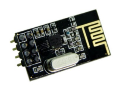
NRF24L01 Transceiver Module
Let’s take a closer look at the NRF24L01 transceiver module. It uses the 2.4 GHz band and it can operate with baud rates from 250 kbps up to 2 Mbps. If used in open space and with lower baud rate its range can reach up to 100.The module can use 125 different channels which gives a possibility to have a network of 125 independently working modems in one place. Each channel can have up to 6 addresses, or each unit can communicate with up to 6 other units at the same time.
The power consumption of this module is just around 12mA during transmission, which is even lower than a single LED. The operating voltage of the module is from 1.9 to 3.6V, but the good thing is that the other pins tolerate 5V logic, so we can easily connect it to an our board without using any logic level converters. Three of these pins are for the SPI communication and they need to be connected to the SPI pins of the our board, but note that each our board board have different SPI pins. The pins CSN and CE can be connected to any digital pin of the our board board and they are used for setting the module in standby or active mode, as well as for switching between transmit or command mode. The last pin is an interrupt pin which doesn’t have to be used.
So once we connect the NRF24L01 modules to the our board we are ready to make the codes for both the transmitter and the receiver. The same maintainer has created an OSI Network Layer implementation using nRF24L01(+) radios driven by the newly optimized RF24 library fork.
Protocol used:
This network layer takes advantage of the fundamental capability of the nRF24L01(+) radio to listen actively to up to 6 other radios at once. The network is arranged in a Tree Topology, where one node is the base, and all other nodes are children either of that node, or of another. Unlike a true mesh network, multiple nodes are not connected together, so there is only one path to any given node. The nRF24LO1+ is a single chip 2.4GHz transreceiver with an embedded baseband protocol engine(Enhanced Shockburst), suitable for ultra low power applications. The nRF2LO1+ is designed for the operations in worldwide ISM Frequency band at 2.400- 2.4835GHz. We can operate/communicate and the nRF by SPI.
The assignment
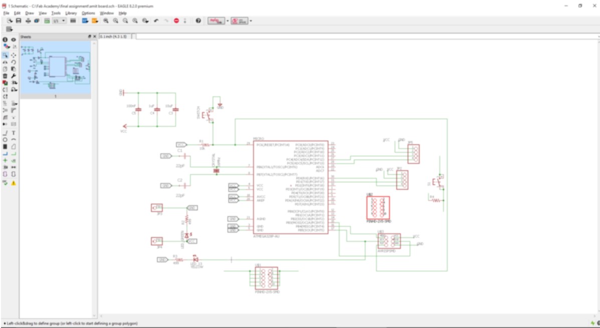
The board I used for this project is described in brief as given.The board file which is to be given to the Protomatt E44 for the PCB fabrication is as shown below:
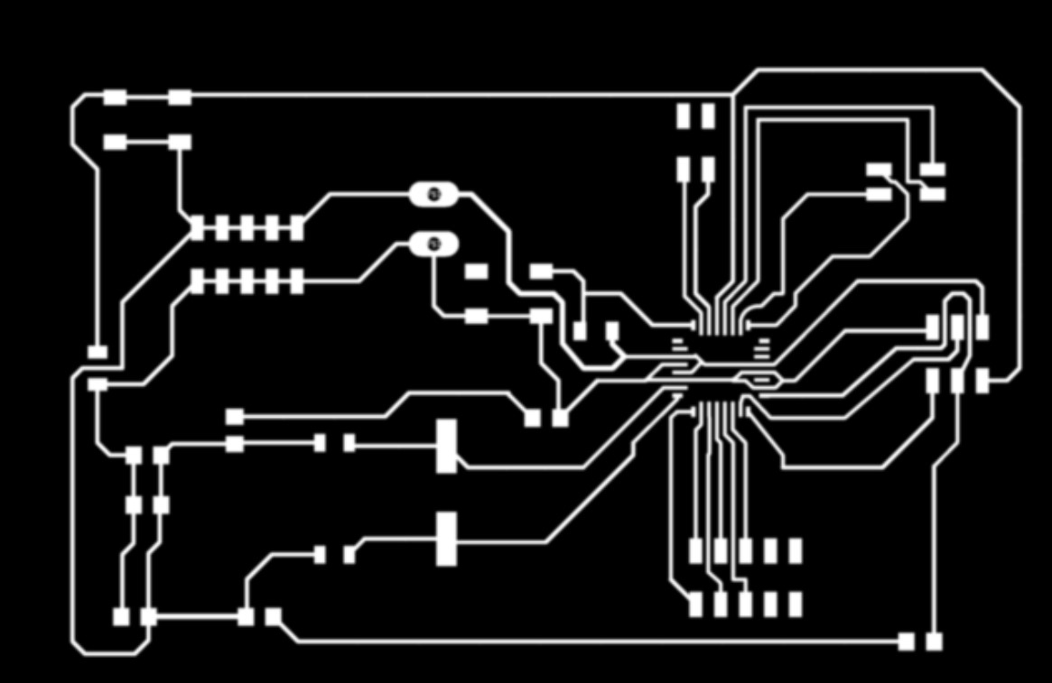
Schematic images of the board which was made in the Eagle software is shown below:
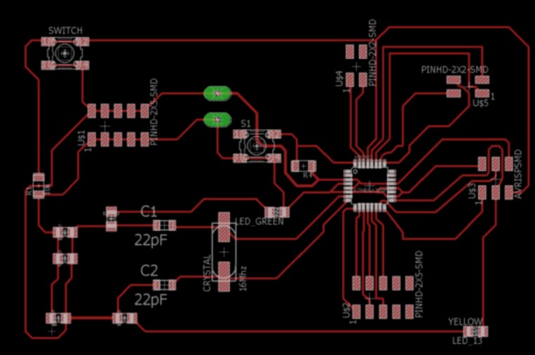
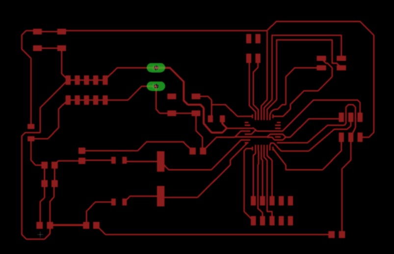
Board images of the final PCB are as follows:
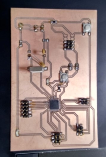
The board after milling and soldering the components shown below:
Connect the following pins to board.
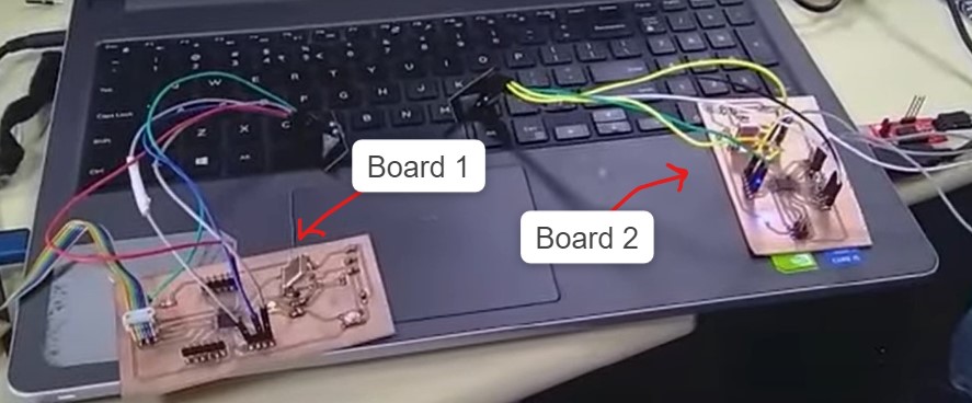
In the image below board one is the transimitter and board 2 is the receiver board.
As soon as the led from board 1 is ON the led from board 2 follows and it ON and when the led is off from the board 1 and then led from the board 2 is also OFF and it follows the board.
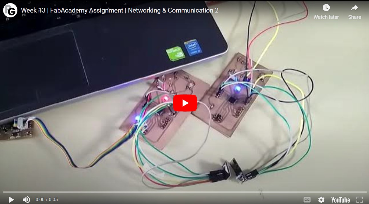
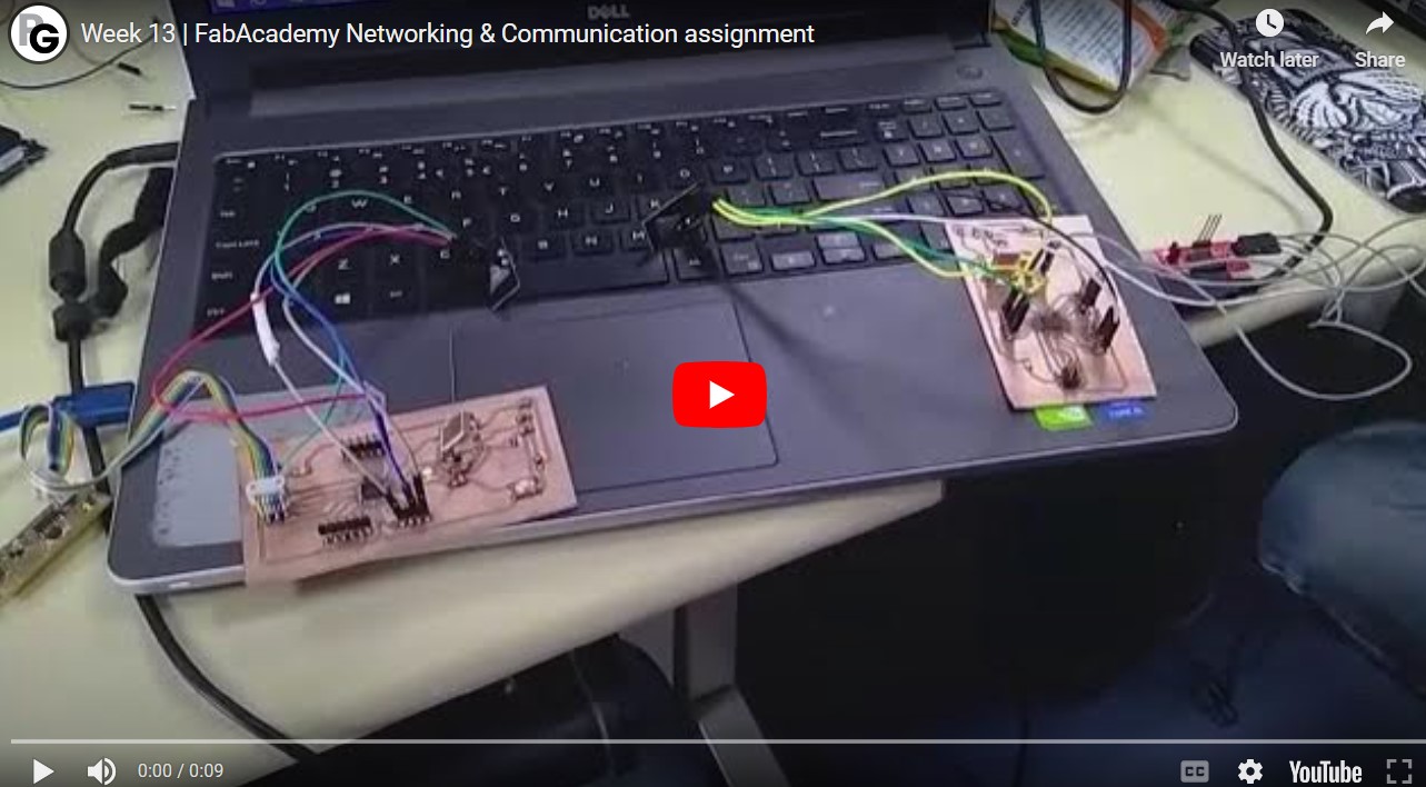
Video demonstration:
Codes
Receiver end code:
              #include <SPI.h>
              #include <nRF24L01.h>
              #include <RF24.h>

              RF24 radio(7, 4);

              const byte rxAddr[6] = "00001";

              void setup()
              {
                while (!Serial);
                Serial.begin(9600);
                radio.begin();
                radio.openReadingPipe(0, rxAddr);
                radio.startListening();
              }

              void loop()
              {
                if (radio.available())
                {
                  char text[32] = {0};
                  radio.read(&text, sizeof(text));
                  if(text==true){
                  digitalWrite(13, HIGH);
                  delay(1000);
                  }
                  if(text==false){
                  digitalWrite(13, LOW);
                  delay(1000);
                 }
              }
Transmitter end code:
            #include <SPI.h>
            #include <nRF24L01.h>
            #include <RF24.h>
              RF24 radio(7, 9); // CNS, CE
              const byte address[6] = "00001";
              bool text =true;

              void setup()
              {
              pinMode(13, OUTPUT);

                Serial.begin(115200);
                radio.begin();
                radio.openWritingPipe(address);
                radio.setPALevel(RF24_PA_MIN);
                radio.stopListening();
              }
              void loop() {
                  if(text==true){
                  digitalWrite(13, HIGH);
                  radio.write(&text, sizeof(text));
                  Serial.println(text);
                  delay(1000);
                  }
                  if(text==false){
                  digitalWrite(13, LOW);
                  radio.write(&text, sizeof(text));
                  Serial.println(text);
                  delay(1000);
                  }
                  text =!text;
                  }
Download files
Board filesArduino IDE Codes
NRF24L01 Datasheet