11. Input Devices
An input device responds to changes in the environment and produces a suitable electrical signal for processing in an electronic circuit.
In all input devices, other forms of energy are transformed into electrical energy.
Basically, an input device is any hardware device that sends data to the microcontroller, allowing you to interact with and control the board. The input devices such as keyboard, mouse, sensors which send data to the microcontroller.
Sensors are usually refer as input devices. Sensors like phototransistor and photo diode that detects the amount of light, temperature sensors, pressure sensors, humidity sensors, fluid sensors, etc.
An input device reacts to changes in the environment around it and produced a electrical signal for processing to an electronic circuit. It is generally grouped into 2 categories; Active and Passive devices.
Active Input Devices
Acive input devices generated a voltage in response to changes around its environment. The following input devices do not need a separate power supply.Examples are:
Passive Input Devices
Passive input devices have resistances which changes according to the environment around it. They need a separate power supply when in use.Examples are:
Using Ultrasonic sensor as input device
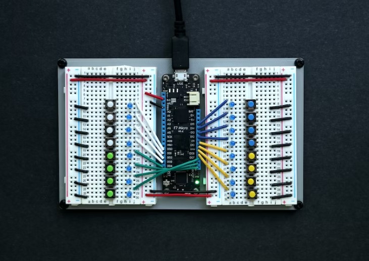
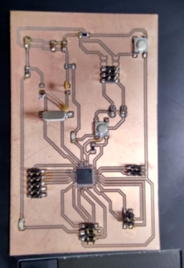
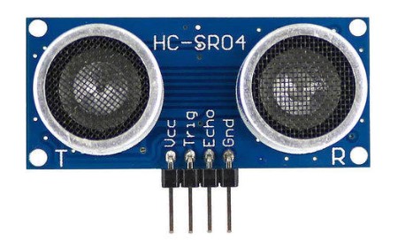
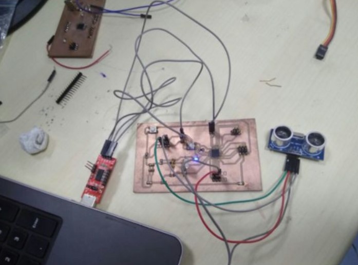
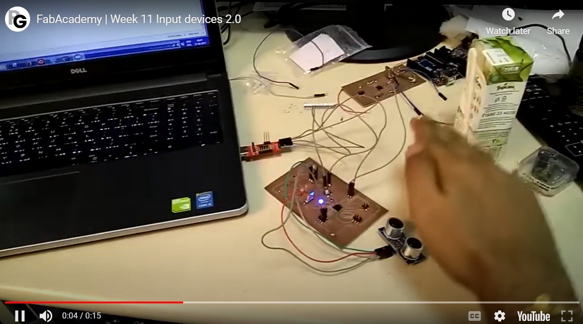
For this assignment I am going to use HC-SR04 which is ultrasonic sensor as input device. I am going to use my final board that I have made which is explained in previous assignment in Output devices. Below are the images of the final board from the previous assignment: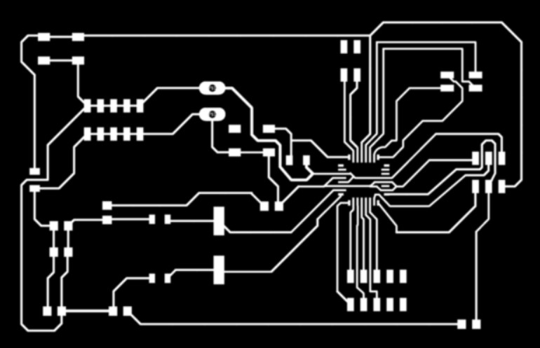
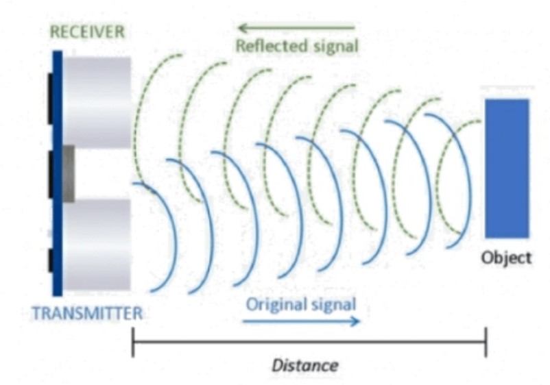
Ultrasonic sensor
Ultrasonic ranging module HC - SR04 provides 2cm - 400cm non-contact measurement function, the ranging accuracy can reach to 3mm. The modules includes ultrasonic transmitters, receiver and control circuit.The basic principle of work:
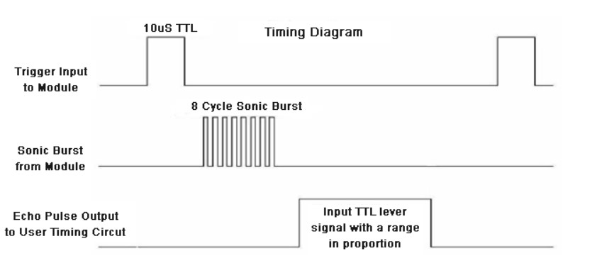
(1) Using IO trigger for at least 10us high level signal,
(2) The Module automatically sends eight 40 kHz and detect whether there is a pulse signal back.
(3) IF the signal back, through high level , time of high output IO duration is the time from sending ultrasonic to returning.
Test distance = high level time × velocity of sound (340M/S) / 2,
Timing Diagram:
Connection Diagram:
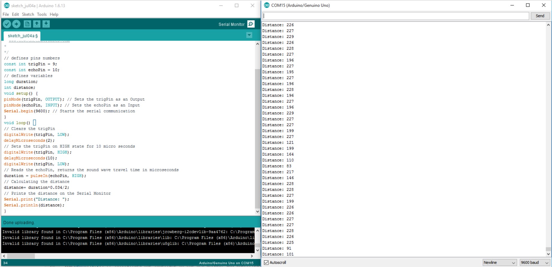
First you have to define the Trig and Echo pins. In this case they are the pins number 9 and 10 on the Board and they are named trigPin and echoPin. Then you need a Long variable, named “duration” for the travel time that you will get from the sensor and an integer variable for the distance.
In the setup you have to define the trigPin as an output and the echoPin as an Input and also start the serial communication for showing the results on the serial monitor.
In the loop first you have to make sure that the trigPin is clear so you have to set that pin on a LOW State for just 2 µs. Now for generating the Ultra sound wave we have to set the trigPin on HIGH State for 10 µs. Using the pulseIn() function you have to read the travel time and put that value into the variable “duration”. This function has 2 parameters, the first one is the name of the echo pin and for the second one you can write either HIGH or LOW. In this case, HIGH means that the pulsIn() function will wait for the pin to go HIGH caused by the bounced sound wave and it will start timing, then it will wait for the pin to go LOW when the sound wave will end which will stop the timing. At the end the function will return the length of the pulse in microseconds. For getting the distance we will multiply the duration by 0.034 and divide it by 2 as we explained this equation previously. At the end we will print the value of the distance on the Serial Monitor.
Arduino code and output:
Below are the working videos of ultrasonic HC- SR04 Sensor:
Switch as a input device
The simple form of the input device is button, which can be simply read by the MCUs.Momentary v/s Latching switches
A Momentary push button function means that when pressed down, it immediately returns to its natural state. For it to either change the function, it’s required to be touched or pressed.
A latching push button function also referred to as maintained, means that it remains in a position until pressed again. It required to be pressed down or touched multiple times to either turn on or off the device or function. It aims to push to make and push to break a cycle and can also be referred to as normally closed push switches.
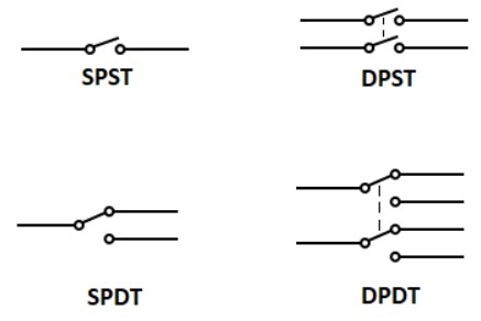
What are SPST, SPDT, DPST, DPDT switches?
SPST means Simgle Pole Single Throw and SPDT means Single pole Double throw and similarly others. What is pole? and What is throw? These questions can be answered better by understanding the image below:
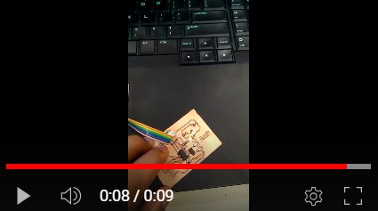
The following video is showing the use of simple push button as a input device, the code is written in a way to turn ON the led and turn OFF the led when the button is pressed.
What does the code do?
We set the pinButton variable as integer 8 and we connect the button at pin 8 on the Board. Then the LED is connected to pin 2 using the resistor in series with it.
Related Products: Switch Slide | Switch Snap Action | Switch Tactile
In the setup() function we set the pin 8 as INPUT and pin 2 as OUTPUT. In the loop() function we read the value of the pin 8 and store it in the variable stateButton. Using a if() function the Arduino makes some decisions: if the button is pressed (stateButton == 1) then give voltage to pin 2 (HIGH), else, if stateButton is not 1 (not pressed) do not output voltage on pin 2.
Use of input devices for Final project
After learning from this, I have also coded a similar version for the final project. The details of the same can be found in the Final project page. The code used there was completely freshly written as attached below. This code was used for one of the initial iterations and focuses on using switch as input device.
        #include <Servo.h>

          Servo myservo;

           int pos = 0;
          int vin = 0;
          const int ledPinRED = 8;
          const int ledPinYELLOW = 7;
          const int ledPinBLUE = 6;
          float valueRED;

          void setup() {
            myservo.attach(9);
           pinMode(ledPinRED, OUTPUT);
           pinMode(ledPinYELLOW, OUTPUT);
           pinMode(ledPinBLUE, OUTPUT);
           digitalWrite(ledPinRED, LOW);
          }

          void loop() {
            valueRED=analogRead(vin);
           float vin = valueRED * (5.0 / 1023);
          if (vin < 0.20)                   // Flush anything below 0.02 volts
            {
              vin = 1.0;
            }
            else
            {
              vin = 0.0;
            }
            delay(100);
            if (vin = 1.0)
            {
              pos = 40;
              digitalWrite(ledPinRED, HIGH);
              myservo.write(pos);              // tell servo to go to position in variable 'pos'
              delay(150);
            }
            else
            {
              pos = 0;
              myservo.write(pos);
              delay(150);
            }


          }
Download files
Arduino IDE codeAtmega328p file