09. Output Devices
An output device is any device used to send data. General example of the output devices are printers, screens, LEDs, motors etc.
I started with understanding output devices first. Output devices can be broadly categorized into several types, including visual output devices, audio output devices, and physical output devices. Let's explore each category a bit in detail first.
Visual Output Devices
These output devices are used to display visual information.Audio Output Devices
These output devices are used to play sound or musicPhysical Output Devices
These output devices are used to create movement or other physical effectsWorking with Servo motor as an output device
So the requirement of this assignment is to add an output device to a microcontroller board and program it to do something. For this assignment I am going to use Servo Motor as output device. I am not going to use my attiny412 board here but going to try out new things in this assignment.In that regards, I am trying to design a PCB to replace my arduino based current electronics in my final project on "Adjustable Hour Glass" I have prepared the final PCB board which I am going to use for this assignment and also the other assignments like input devices. The board is same as the Arduino UNO Board because it has the same IC i.e. 328p, and does all the functionality of UNO.
Steps followed are as follows:
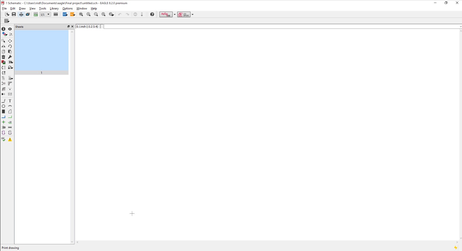
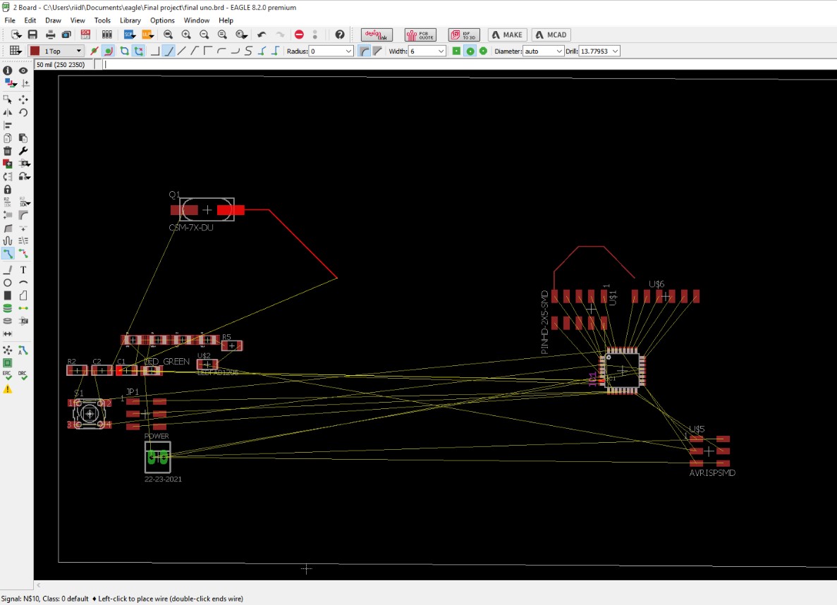
1. So I have used EasyEDA many times, and Neil mentioned to try new things out so I used Eagle Software for designing of my final PCB for my final project. and couple of these input output device assignments.
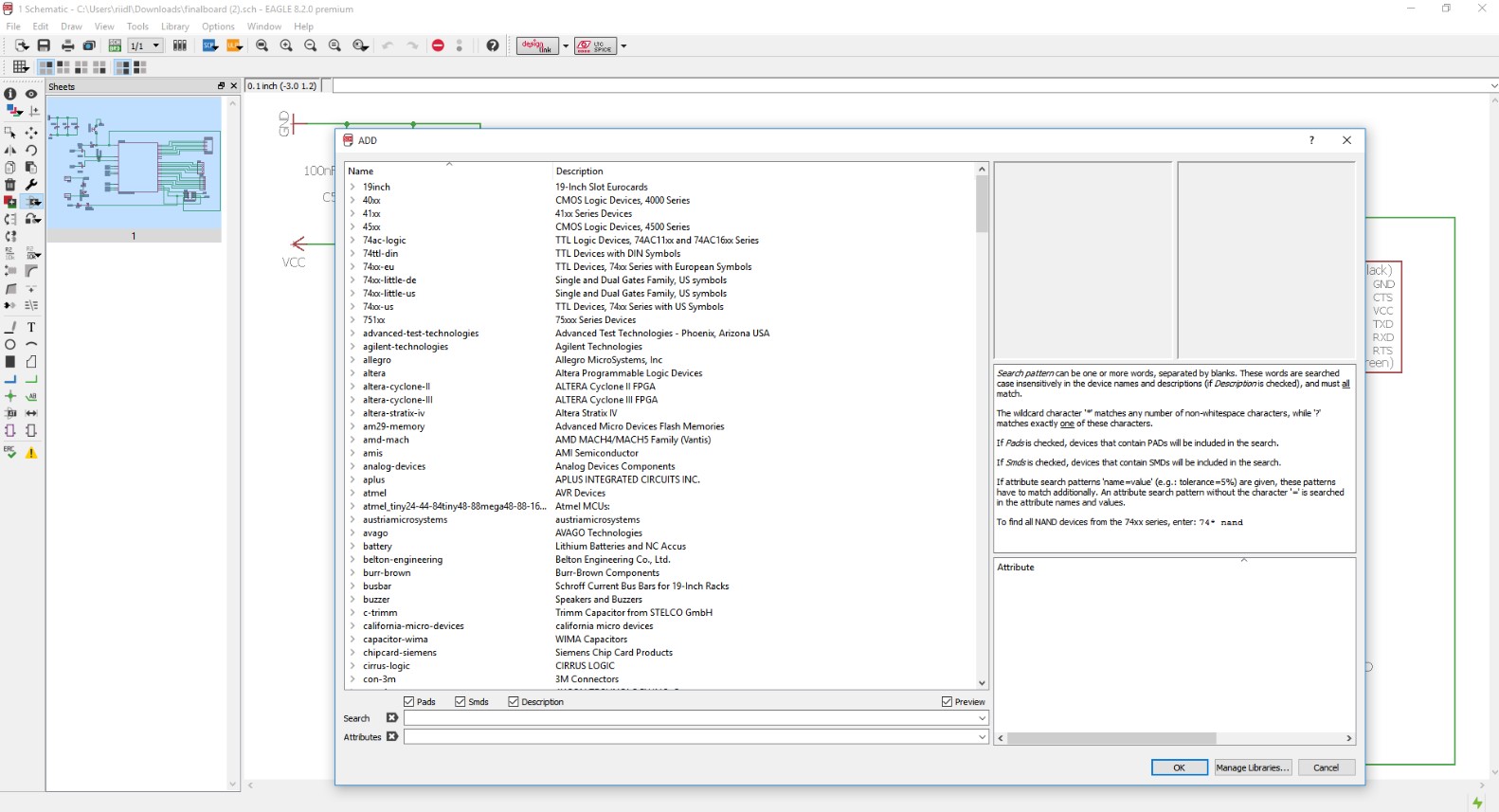
2. Use the ADD command to add the components to the design layout which is available under the command button bar.
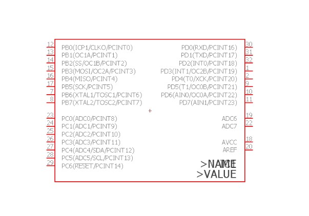
3. Add the atmega328p which is the arduino UNO chip.
4. Add all the components such as resistor, capacitor, Leds, button, AVRISP SMD header pins, etc.
5. Use the command net to join the two components pins with each other.
6. After connecting all the component with each other, to know whether all the components are connected or not with the ERC command.
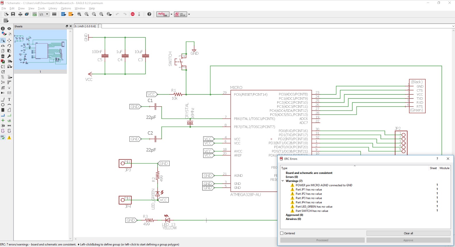
7. If there is no error from the ERC error dailaog box, we are ready to switch from the schematic file to board file.
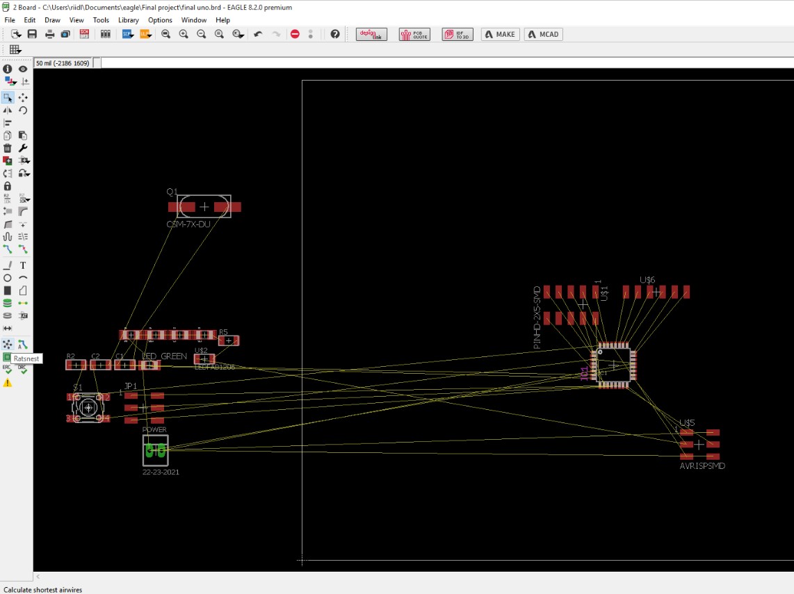
8. In the Board version, after arranging the components in the proper place, then route the wire with the routing option available from the command button bar. Before using the route option, select the ratsnet to so that the number of wires should be reduced.
9. Then use the route option to make respective connections.
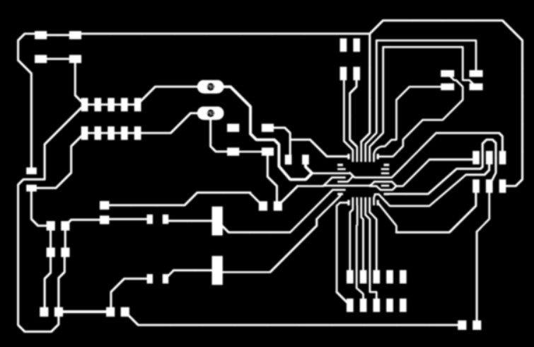
10. Then export the file for fabrication. Save it in .png format 600dpi monochrome.
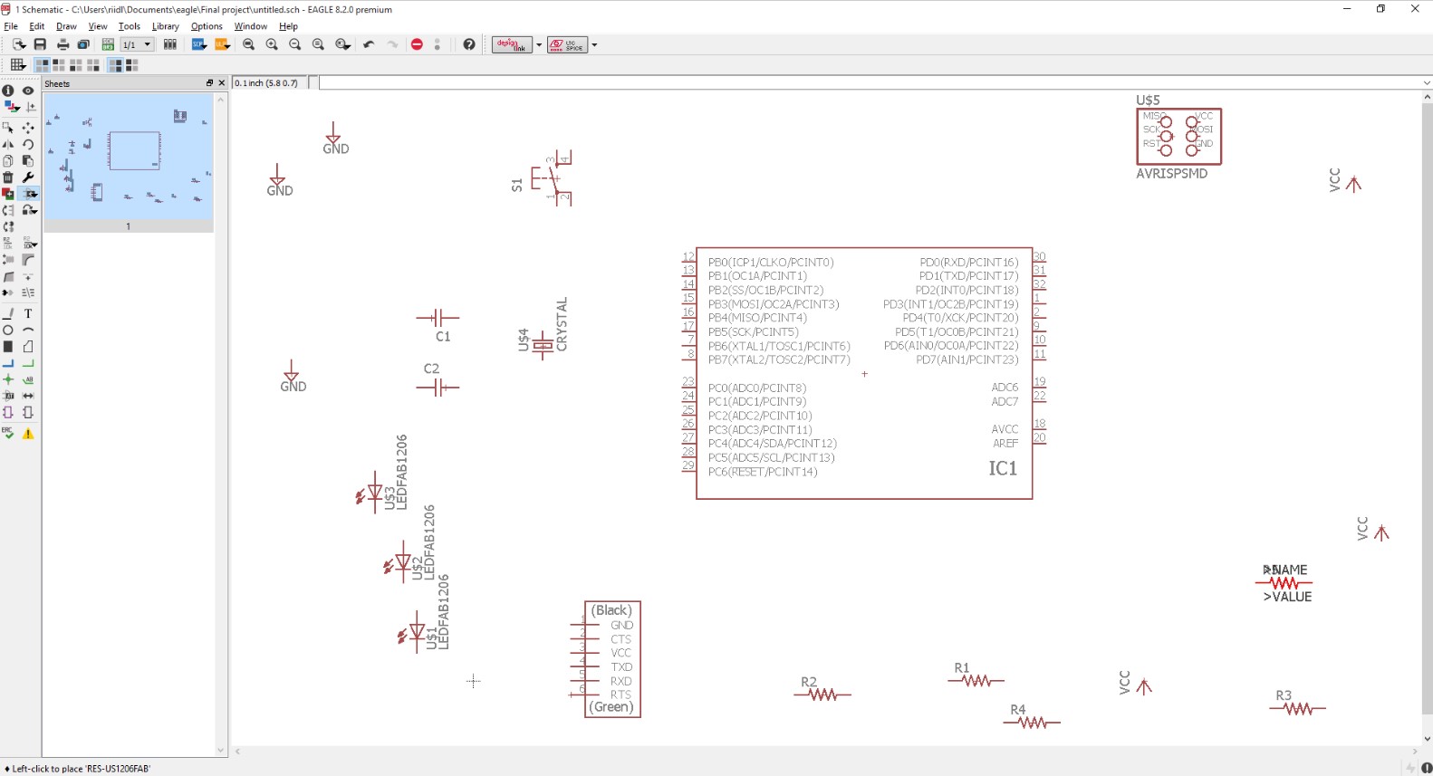
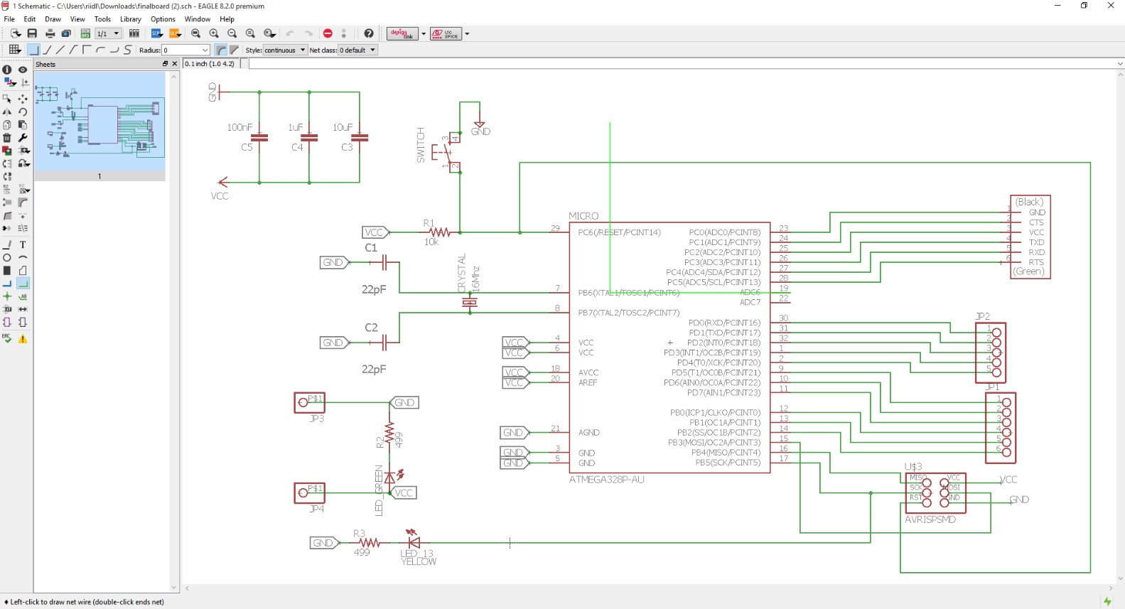
Below are the images of the final board:
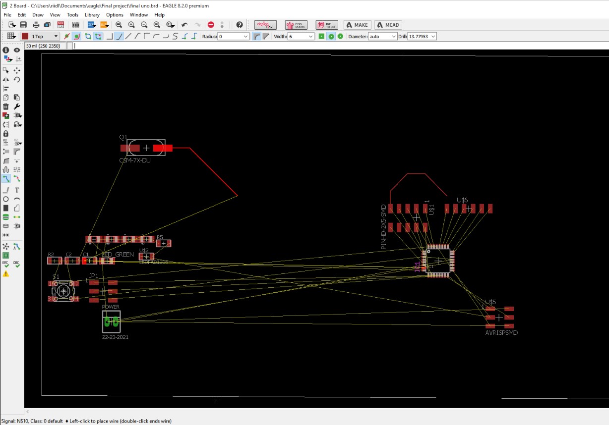
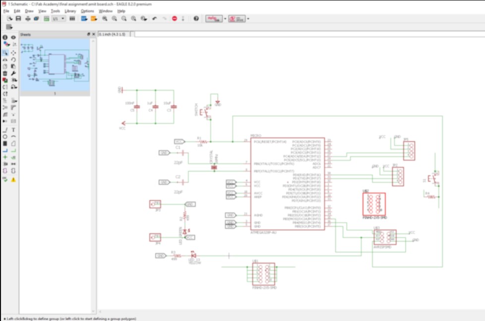
Schematic images of the board which was made in the Eagle software.
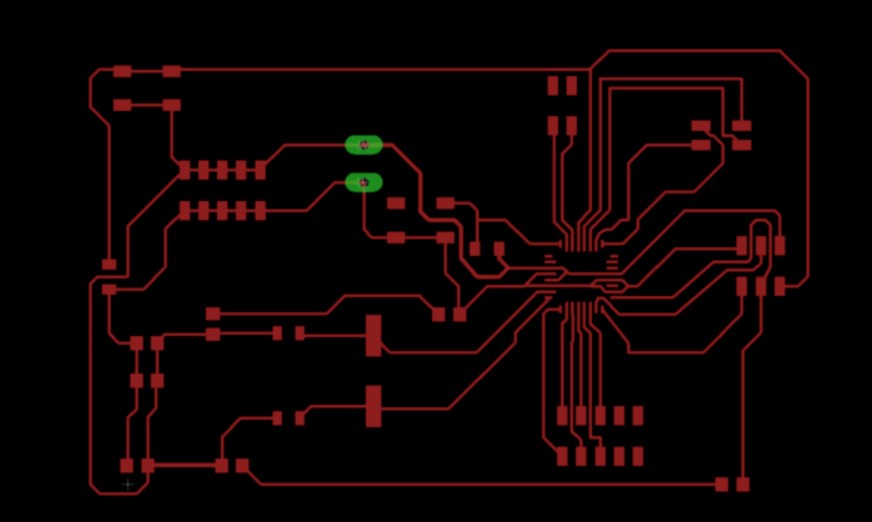
Board images of the final PCB.
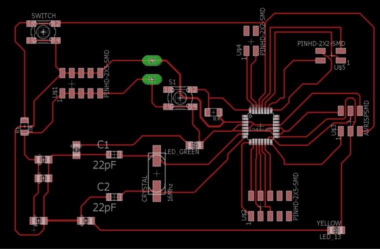
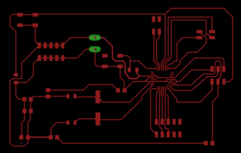
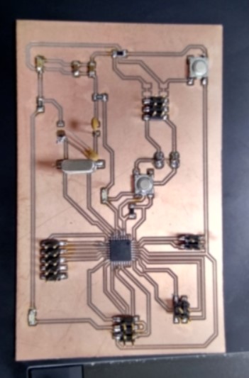
Image of the board after milled.
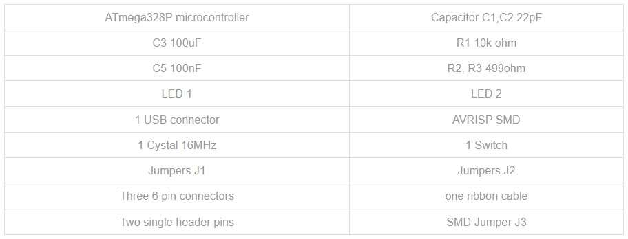
Components needed for the board:
What is a servo Motor?
The servo motor is most commonly used for high technology devices in the industrial application like automation technology. It is a self contained electrical device, that rotate parts of a machine with high efficiency and great precision. The output shaft of this motor can be moved to a particular angle.Mechanism of servo Motor:
A servomotor is a closed-loop servomechanism that uses position feedback to control its motion and final position. The input to its control is a signal (either analogue or digital) representing the position commanded for the output shaft.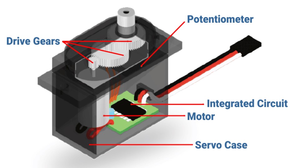
Types of servo Motor:
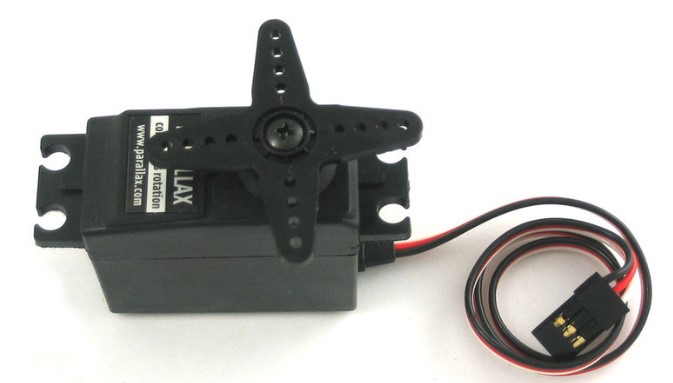
Servo motors are classified into different types based on their application, such as AC servo motor, DC servo motor, brushless DC servo motor, positional rotation, continuous rotation and linear servo motor etc. Typical servo motors comprise of three wires namely, power control and ground.
I am going to use Continuous Rotation Servo Motor.
The basic code of servo motor.
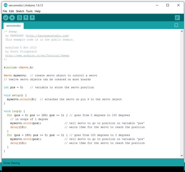
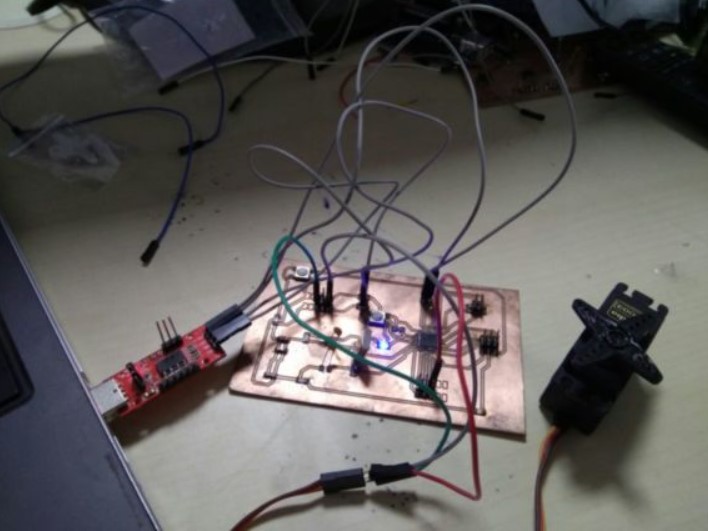
Connection circuit of servo motor where signal pin of servo motor is connected to digital pin 9 on the board.
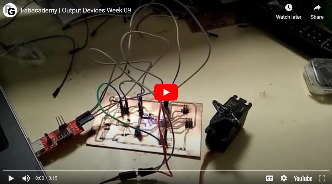
Below is the working video of Servo motor as output device.
Use of output devices for Final project
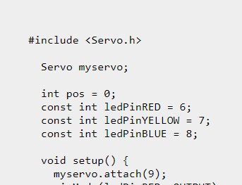
After learning from this, I have also coded a similar version for the final project. The details of the same can be found in the Final project page. The code used there was completely freshly written as attached below. This code was used for one of the initial iterations and focuses on using Servo motor as output devices.
          #include <Servo.h>

            Servo myservo;

            int pos = 0;
            const int ledPinRED = 6;
            const int ledPinYELLOW = 7;
            const int ledPinBLUE = 8;

            void setup() {
              myservo.attach(9);
              pinMode(ledPinRED, OUTPUT);
              pinMode(ledPinYELLOW, OUTPUT);
              pinMode(ledPinBLUE, OUTPUT);
            }

            void loop() {
                for (pos = 0; pos <= 180; pos +=1) {
                  myservo.write(pos);
                  delay(150);
                }
                for (pos = 180; pos >= 0; pos -=1) {
                  myservo.write(pos);
                  delay(150);
                }
                digitalWrite(ledPinRED, HIGH);
                digitalWrite(ledPinYELLOW, HIGH);
                digitalWrite(ledPinBLUE, HIGH);
            }
New Learnings - Adding code as a sample in your HTML file
So for convinience, I was adding many of the times some arduino codes on my pages directly by just enclosing it in "pre and code" which is defined in style.css file. But there was one error, the #include Servo.h was not being displayed properly as it was read by the HTML as its own syntax. As shown in the image below: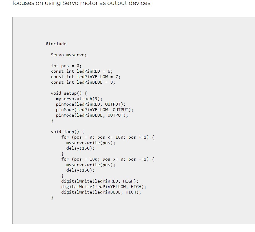
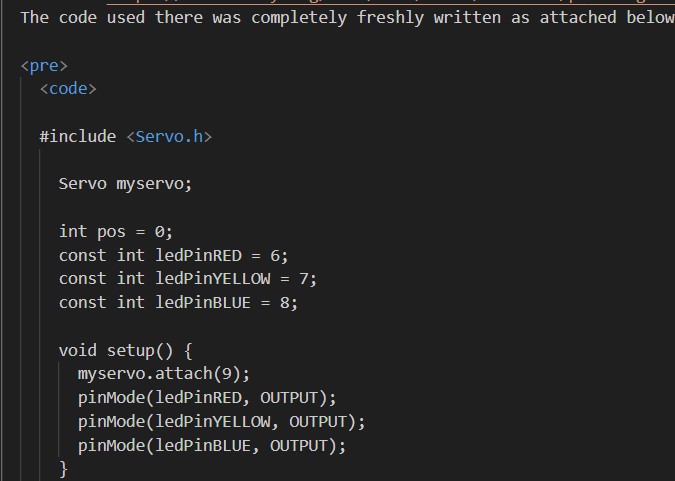
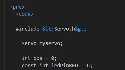
So to avoid that to happen, either always make sure to attach codes as zips or use the following solution.
Use < and > as shown in the image below:
Download files
Arduino IDE codeAtmega328p file