7. Computer controlled machining
So Computer controlled machining includes Computer Numerical Control (CNC) machining, which is basically a manufacturing process in which pre-programmed computer software dictates the movement of factory tools and machinery. The process can be used to control a range of complex machinery, from grinders and lathes to mills and CNC routers. This week, we will explore CNC machines and its usage to build something big!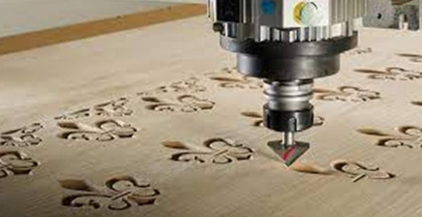
CNC Machines and its types
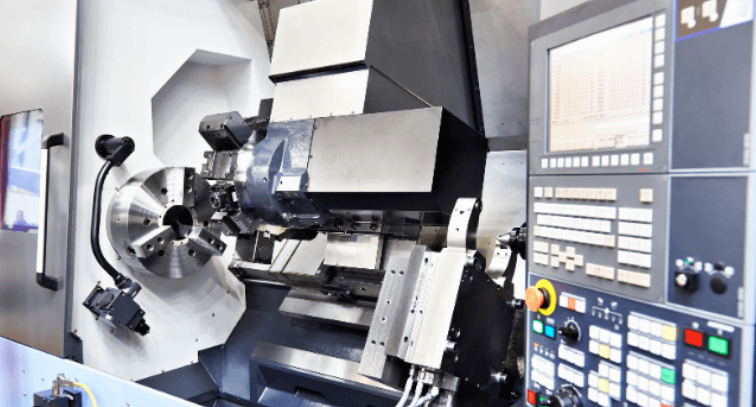
CNC stands for computer numerical control and these machines play an important role in the manufacturing industry. These complex machines are controlled by a computer and provide a level of efficiency, accuracy and consistency that would be impossible to achieve through a manual process. Just as there are many different parts that CNC machines can make, there are also various types of CNC machines used to accomplish this. Each machine differs in construction, the way they operate and the types of product they can make. Let's first understand different CNC machines as listed below: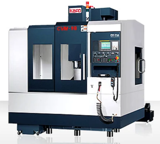
Apart from these most commonly used CNC machines, there are also some other CNC machines as listed below:
Understanding riidl's CNC router
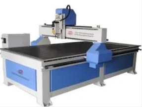
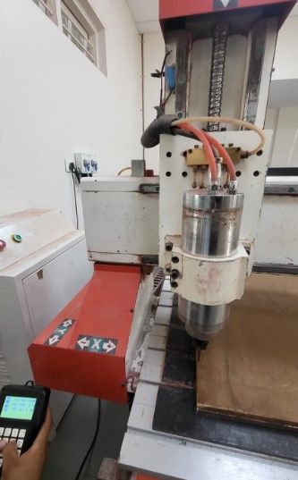
riidl's FABLAB has a CNC router inhouse and thus we are going to make something big using a CNC Router and wooden ply. CNC router at our FABLAB is as shown in the image below: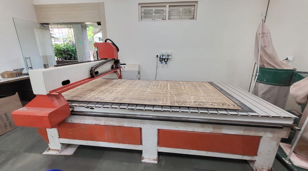
The CNC router consists of following parts:
Safety instructions for using the CNC router
Making something big
So for the "Make something big" assignment, I decided to build the "shoe rack" I had been planning to have at my office since long. The steps from ideating to actually assembling it together are explained below in detail:Step 01: Ideation
Visualising the storage space was very important at first. So we have a bunk bed at home to both save space as well as childish craving to have one. But due to the RCC walls and the bunk bed dimensions, there is an huge empty space left between the bed and the wall of our bedroom. Inorder to utilise this space in a more efficient way, a storage space is an ideal solution. But ofcourse it needs to be customised based on the constraints and dimensions of the cavity created between my bed and the wall.
These contraints were first noted down to define a volume claim as follows:
Based on these constraints, I sketched few ideas/concepts on paper first as shown in the figure below:
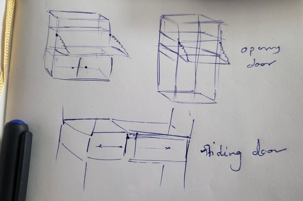
The storage space is designed of 12 components in total:
2 on the sides, 6 alternates at the back, 2 in the middle and 1 at the top and bottom each
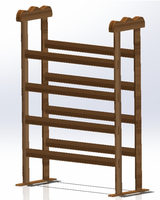
But then I felt holding such a storage space without glue and fasteners would be a difficult task. Atleast in first attempt. So I decided to pivot and change my idea. SO I designed a simple shoe rack. I directly started designing it on Solidworks this time as it was supposed to be the simplest one. I will first get the simple things done and if I get time, I will come back to my storage space and get it cut at well.
I also have plans to try parametric designs like a CNC cut table and chair combo. Or a work design table as shown below:
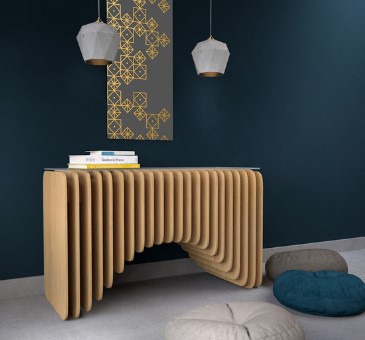
Hopefully I will get time in coming days to try these big things out.
Step 02: Conceptualisation
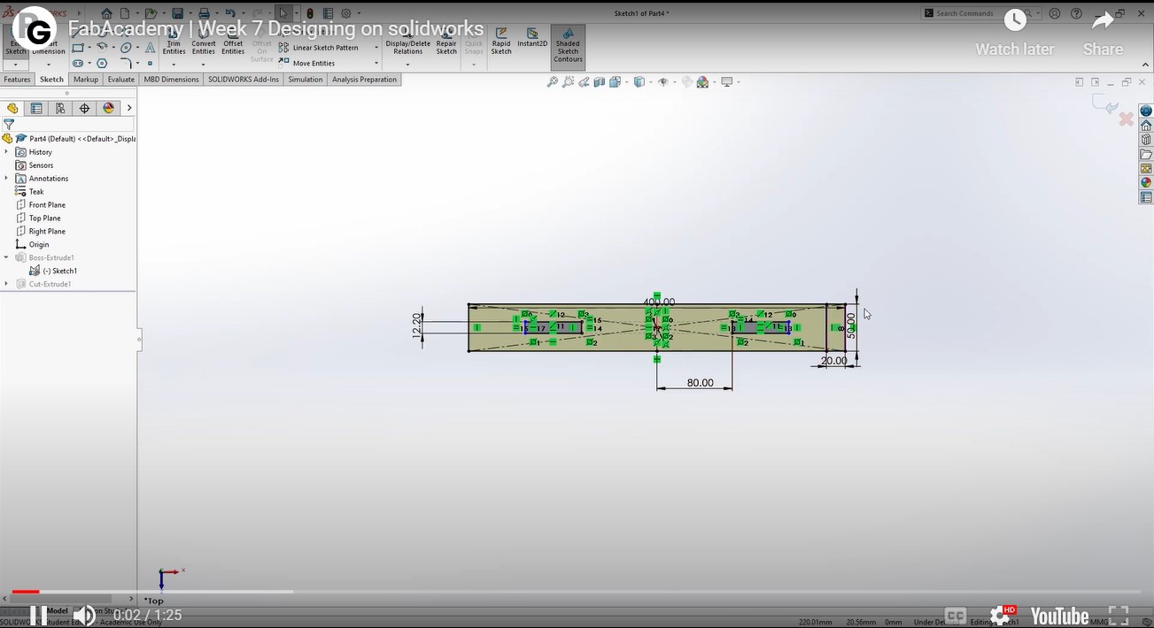
The design was designed on Solidworks and the interference slots were designed based on the material thickness and the tool kerf The design is planned to be ideally assembled without glue or anything. The solidworks design looks as shown in the figures below:
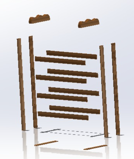
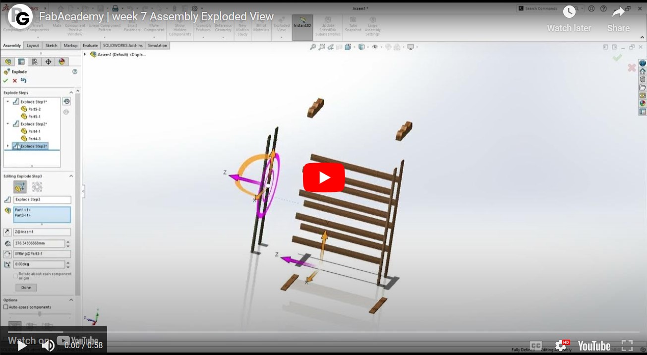
The exploded view above shows the assembly order as well.
The parts designed are described in the video below:
The exploded view order of instructions is explained in the video below:
Few important stages/decisions during the designing phase:
1. Decide the material in advance
2. Talk to the vendor about the availability of the desired thickness of the material
3. Design the interference fits based on the material thickness and kerf of the machine
4. Possibly test the interference fit with small test cuts first
5. Know and understand the end tool your lab has. (For example 6mm bit will not be able to give a proper fit for 6mm thick ply)
6. The material thickness needs to be atleast 2 to 3mm more than bit size.
Step 03: Prototyping
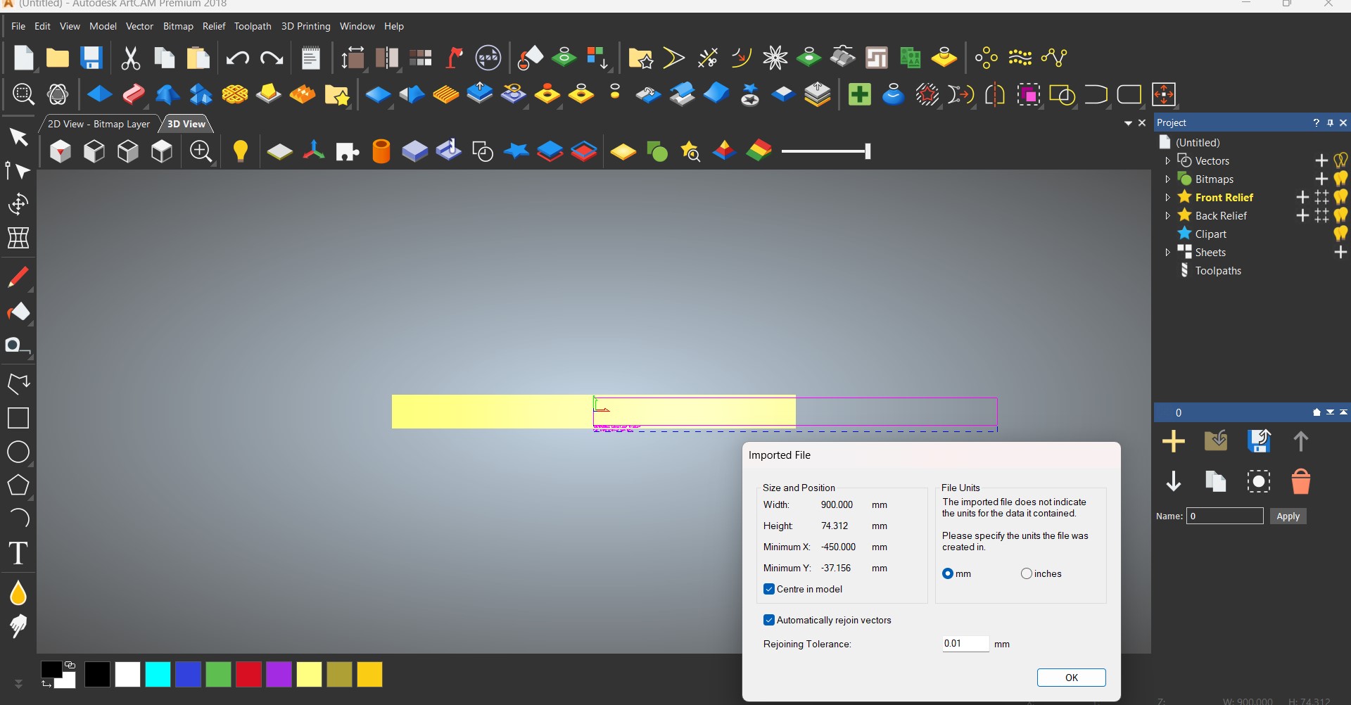
Once the design is ready, it needs to be exported in XYZ format using Autodesk ArtCAM. Solidworks can't export in that file format. So I exported by design from Solidworks in .iges file, opened it again in Autodesk ArtCAM and exported the file in the right format. The toolpath is defined in this file itself. Once the file is ready, its time to go to the machine! The toolpath is designed on ArtCAM software.
Exploring the CNC router
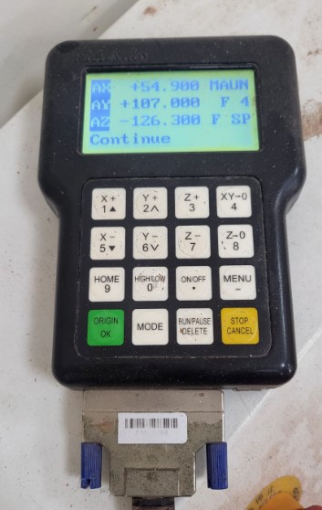
The CNC router at riidl is a pretty old one but still efficient enough at its cutting.Step 01: Homing the machine
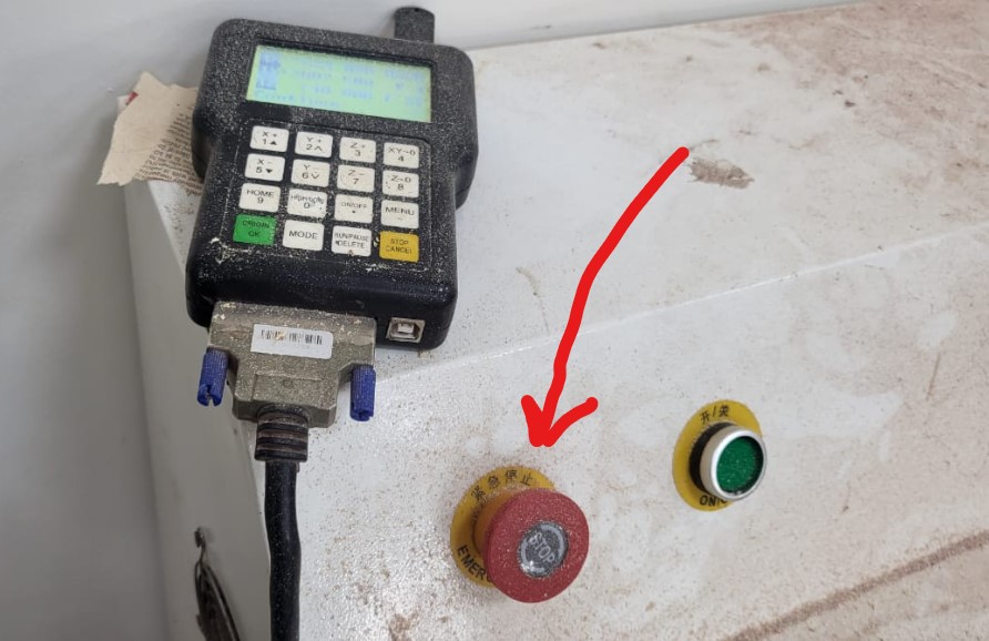
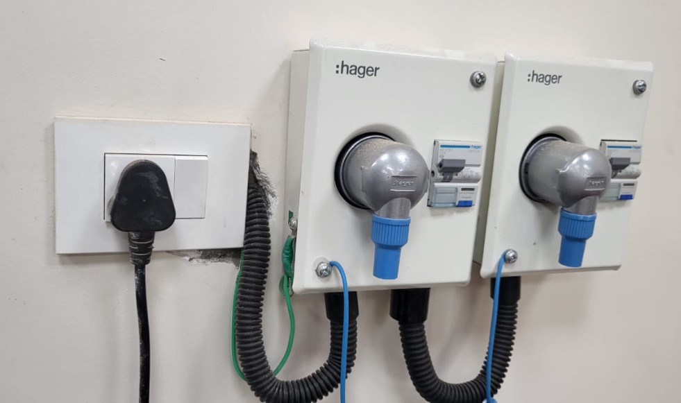
Turn the Machine ON by turning ON the MCBs as shown. Then you can manually move the spindle in X, Y and Z axis using the controller. The red button shown in the second image below is for emergency stop in case of emergency during the operation of the machine.
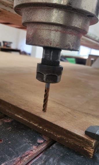
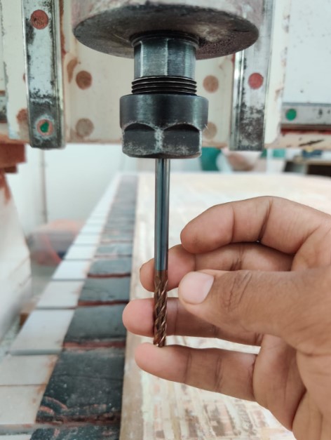
Step 02: Setting the tool
The tool we use is a 6mm diameter end mill tool. The tool is mounted to the spindle as shown below.
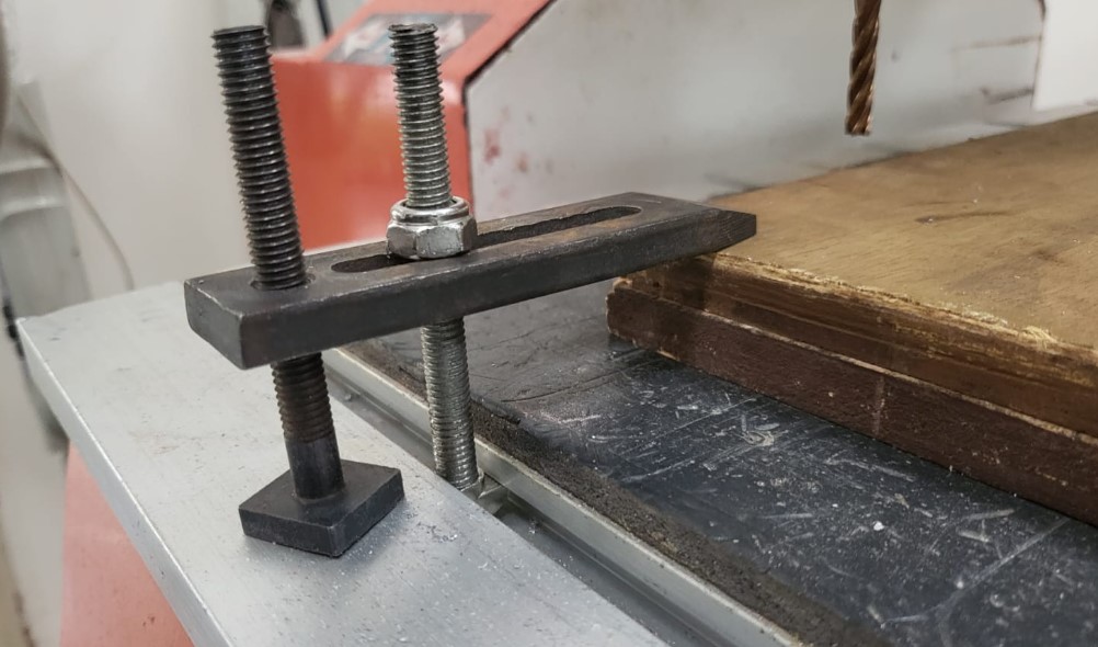
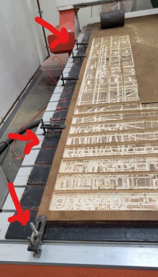
Step 03: Adding the plywood sheet and clamping
Once the tool is set, the next step is to put the plywood sheet you want to cut on the bed and clamp it ideally from all sides.
Step 04: Uploading the file and settings
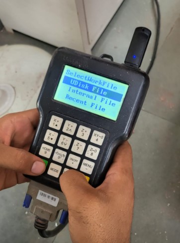
Put the file in a pendrive and connect the pendrive to the controller.
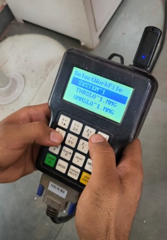
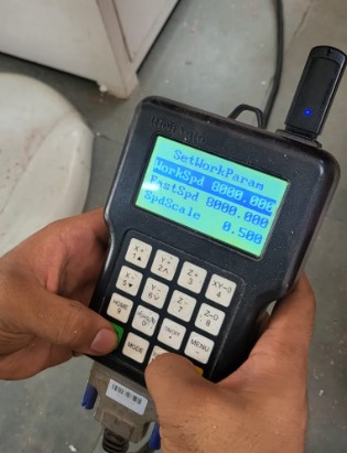
Choose the Udisk > choose you r file name > set the speeds as shown > Start cutting
Note: If the pendrive has multiple files, it takes a lot of time to load on the controller. So it is better if the pendrive has only the toolpath file that you want to cut.
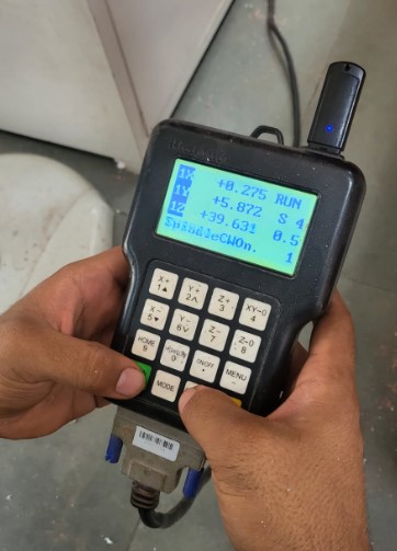
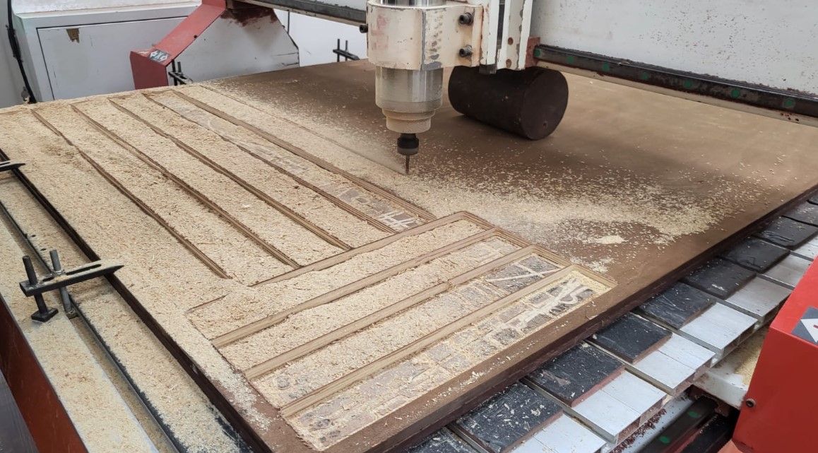
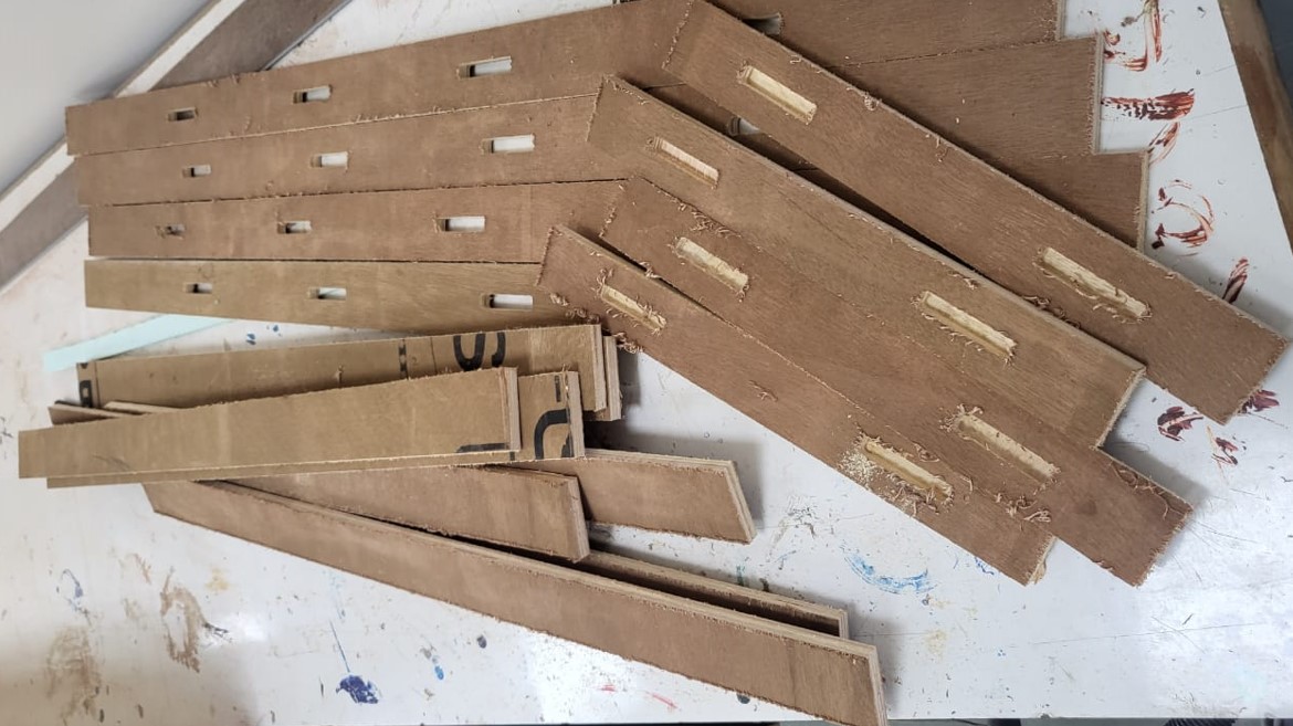
Step 05: Cutting the file
Now the machine endeffector follows the toolpath set and cuts the files.
Step 06: Post processing cut files
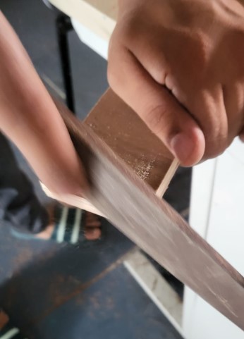
The wooden ply needs to be post processed by sand paper or a wood file to remove any burrs and sharp edges.
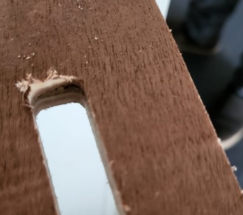
Note: One thing I missed is the fillet that you get at the corners of the cutting. You should ideally add butterfly cut at such corners to relief the corners. As a result of which, I had to sand down the corners using a triangular file as shown below:
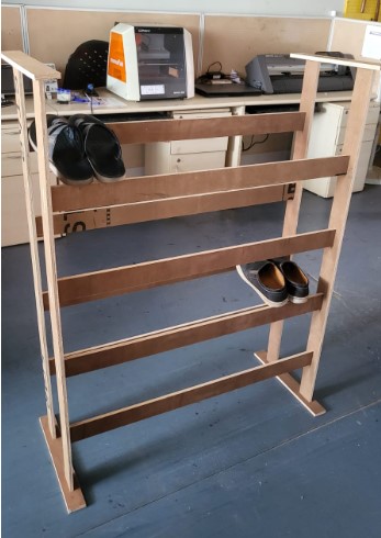
Step 07: Assembly
Final step is the assembly of the same. The assembly was pretty simple and is basically snapping the right parts into right slots by referring to the exploded view.
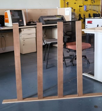
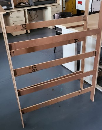
Final Product
The shoe rack is in use at riidl 520 workspace.

Download design files
Solidworks zip fileDXF files zip