4. Embedded Programming
Programming week! My weak spot as of now. Programming is one of those sectors that I haven't explored much yet and are completely new to me. Previously I have had only used Arduino in an extensive way. Other microcontrollers and chips are beyond my knowledge as of now. But sounds interesting! I am going to explore these in coming weeks in detail This week's assignment is to read and understand the datasheet of any one microcontroller and then program for one. Let's start with the basics first...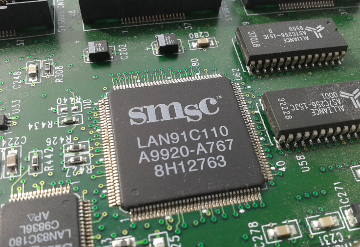
What is programming?
Programming involves instructing computers to perform tasks. It could be a simple task like displaying the sum of two numbers or solving complex problems like the operation of self-driving cars. ALso, it is often confused between programming and coding being more or less the same. THe infographic below shows the difference between the same.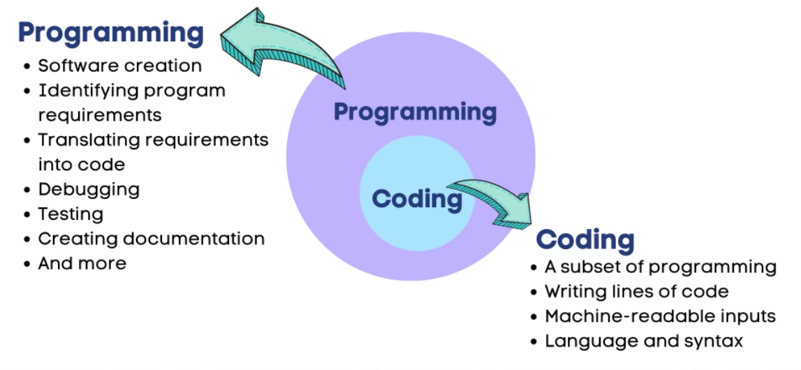
What exactly is a programming language?
A programming language is a set of instructions written by a programmer to deliver instructions to the computer to perform and accomplish a task. This set of instructions is usually viewed as incomprehensible code structured following a definite programming language syntax.
What is a microcontroller?
A microcontroller is an integrated circuit (IC) device used for controlling other portions of an electronic system, usually via a microprocessor unit (MPU), memory, and some peripherals. These devices are optimized for embedded applications that require both processing functionality and agile, responsive interaction with digital, analog, or electromechanical components.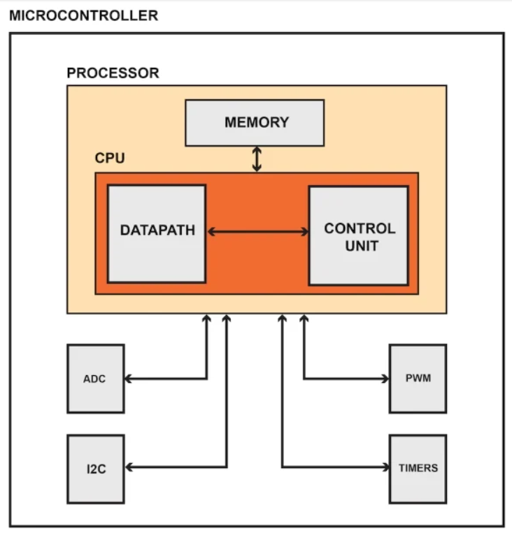
What is embedded programming?
An embedded programming language is a programming language that developers use in embedded systems. In general, the languages offer low-level access to the device hardware. Developers use several common programming languages for embedded systems. The most used languages include:
Understanding the datasheet of ATmega 2560
The ATMega2560 from Atmel is an 8-bit low-power microcontroller that is found in the popular Arduino Mega development board. It is based on the 8-bit AVR RISC architecture and has 256KB flash memory, 8KB SRAM, and 4KB EEPROM. It also has a wide variety of peripherals, including timers, counters, PWM generators, a comparator, and ADCs. It can be clocked up to 16MHz with a 5V supply.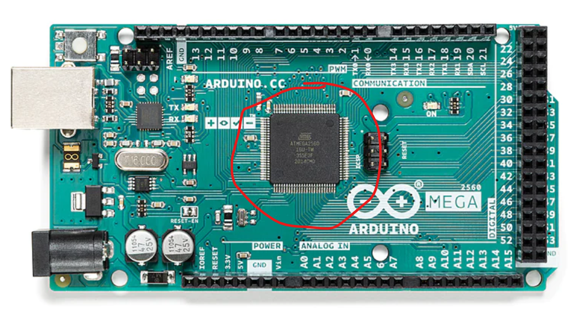
A typical datasheet of a microcontroller contains pinout configurations, internal block diagram, pin descriptions in details, architectural overview and a lot of things. The pinout for ATmega2560 is shown below:

Block diagram of ATmega2560:
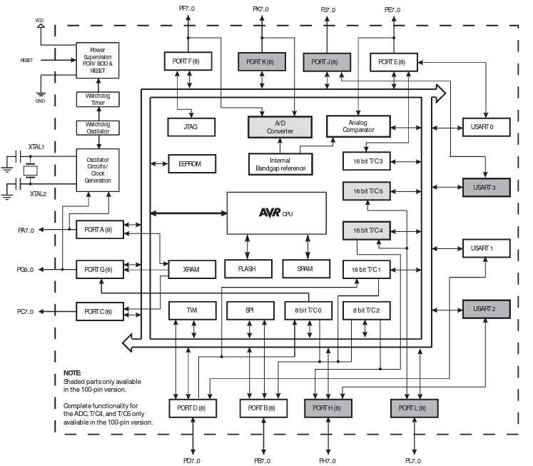
The datasheet for ATmega can be referred from this link: ATmega 2560 Datasheet
Programming a microcontroller development board
The development board I chose to experiment on is ESP32. Through this, we will learn the basics of programming a development board, how to write a code, upload a code, interact with input output pins and how to communicate. The software and hardware required for this is basically an IDE software application and the development board itself. For the software, we will use Arduino IDE software. Learn how t0 download and install Arduino IDE here: Arduino IDE installation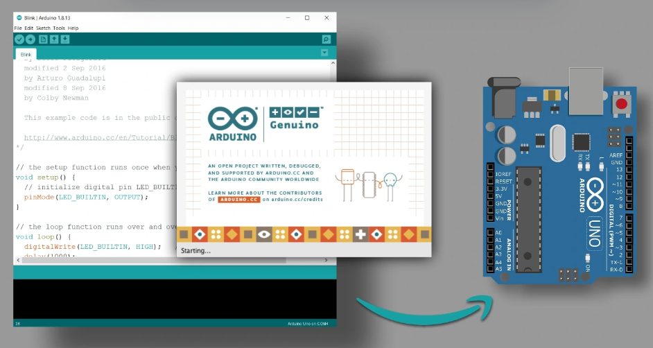
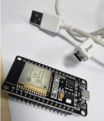
For the hardware, we just need the ESP32 development board and the USB cable to connect to the laptop. THe ESP32 development board can be bought online here: ESP32 development board
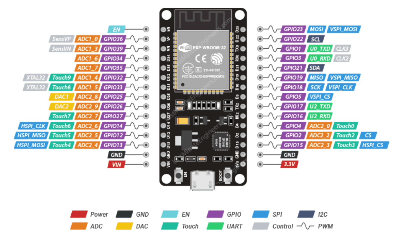
ESP32 pin configuration is as shown in the figure below:
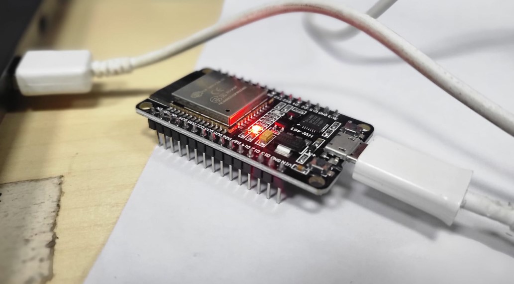
Step 01: Connect ESP32 Board to system using USB cable
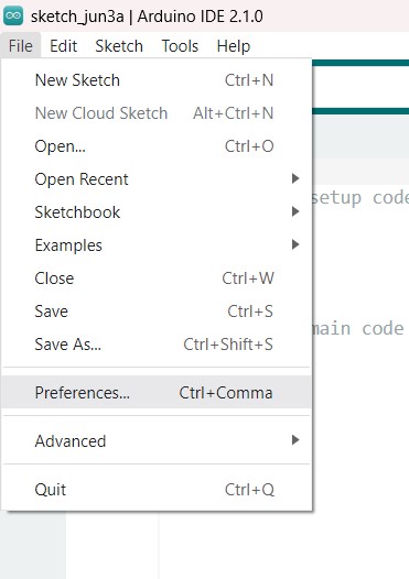
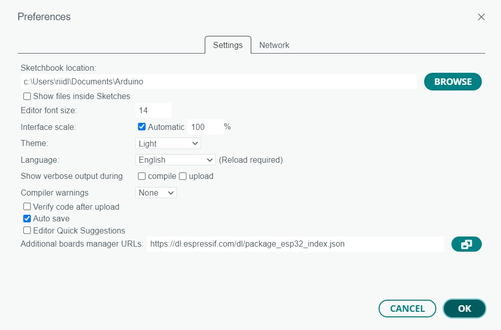
Step 02: Open the Arduino IDE, go to File -> Preferences and enter the following URL in the Additional Boards Manager URLs
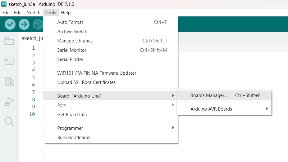
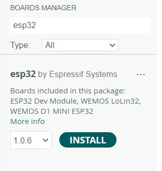
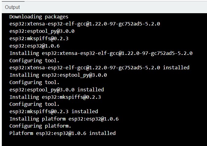
Step 03: Then go to Tools > Board > Boards Manager. Search for ESP32 and install the ESP32 by Espressif Systems board definition
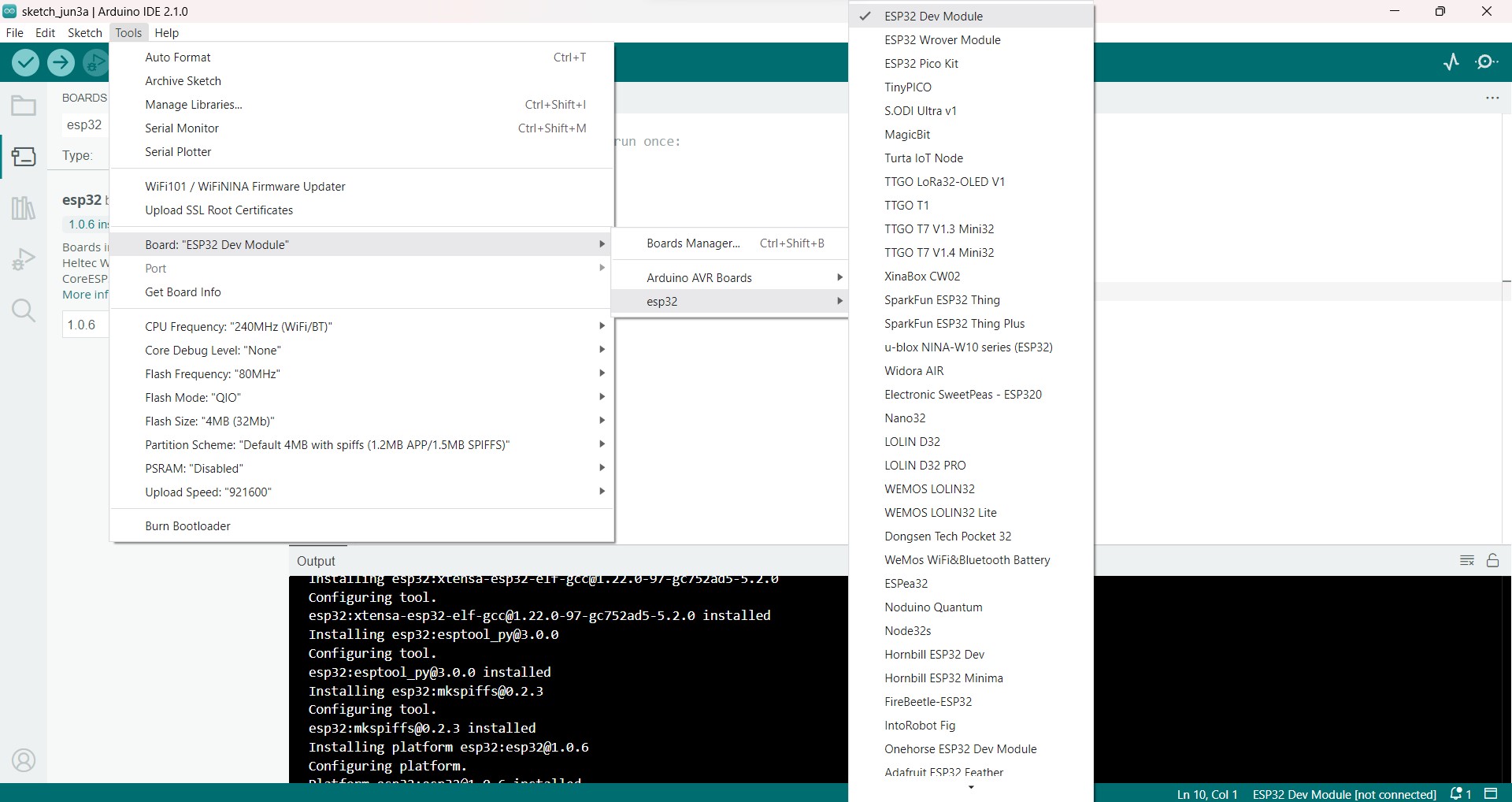
Step 04: Select ESP32 Dev Module as the board
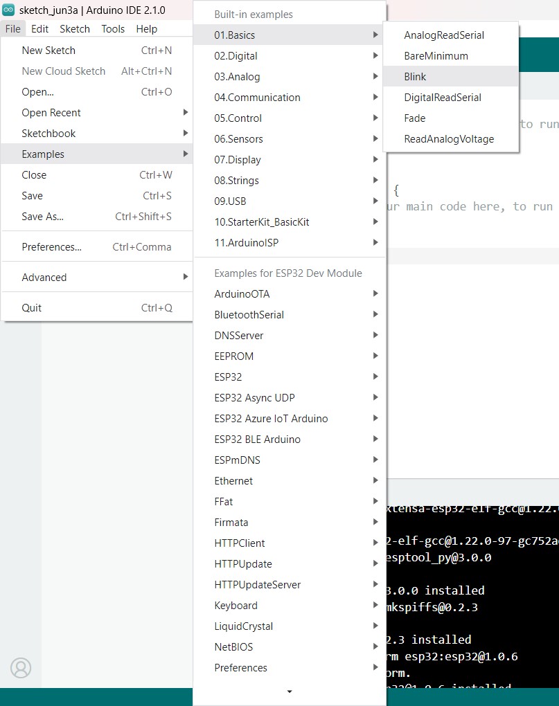
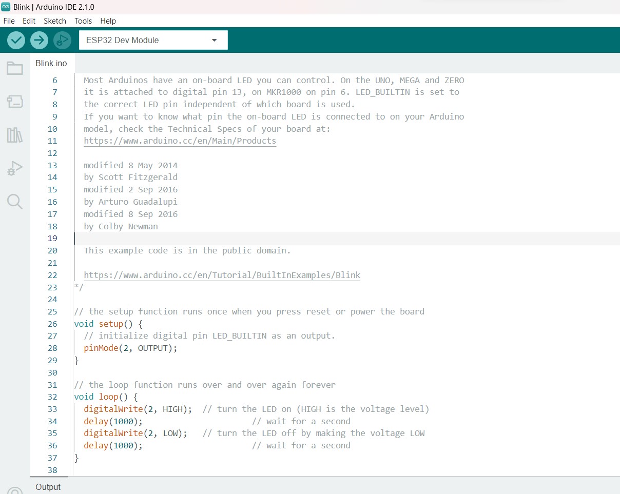
Step 05: Upload the Blink Program: Go to File > Examples > 01.Basics > Blink to open the Blink example program
Step 06: Make changes as per Board, for ESP WROOM 32, the LED pin is “2”. So either define LED BUILTIN as 2 or replace the same with “2”.
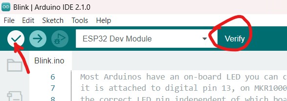
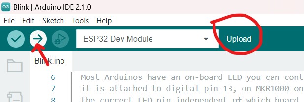
Step 07: When the programming is finished and compiled, it must be uploaded to the board.
Code
        /*
  Blink

  Turns an LED on for one second, then off for one second, repeatedly.

  Most Arduinos have an on-board LED you can control. On the UNO, MEGA and ZERO
  it is attached to digital pin 13, on MKR1000 on pin 6. LED_BUILTIN is set to
  the correct LED pin independent of which board is used.
  If you want to know what pin the on-board LED is connected to on your Arduino
  model, check the Technical Specs of your board at:
  https://www.arduino.cc/en/Main/Products

  modified 8 May 2014
  by Scott Fitzgerald
  modified 2 Sep 2016
  by Arturo Guadalupi
  modified 8 Sep 2016
  by Colby Newman

  This example code is in the public domain.

  https://www.arduino.cc/en/Tutorial/BuiltInExamples/Blink
*/

// the setup function runs once when you press reset or power the board
void setup() {
  // initialize digital pin LED_BUILTIN as an output.

  pinMode(2, OUTPUT);
}

// the loop function runs over and over again forever
void loop() {
  digitalWrite(2, HIGH);  // turn the LED on (HIGH is the voltage level)
  delay(1000);                      // wait for a second
  digitalWrite(2, LOW);   // turn the LED off by making the voltage LOW
  delay(1000);                      // wait for a second
}
Embedded programming for my final project
So I did experiment with some sample examples from Arduino IDE to get a good hold over the syntax and understand the basics of coding. Later, it's time to experiment and explore code that will work for my final project. So for that, initially in the second iteration phase of the project, I want to try out the working of my output and input devices. So the circuit I used was to test the functioning of right LEDs when the corresponding switch is turned on and also the direction the servo motor turns when the corresponding switch is turned on. The circuit diagram design looks like the one I tried on TinkerCAD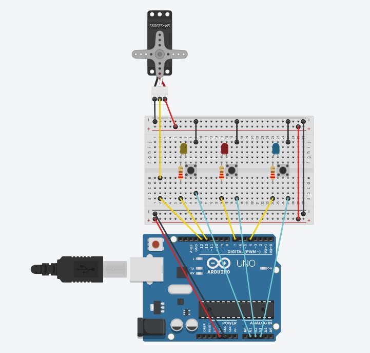
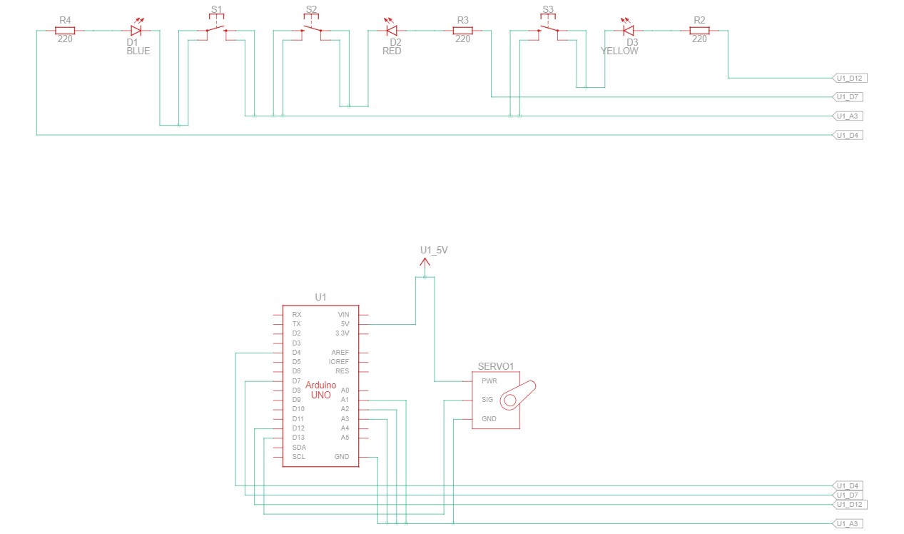
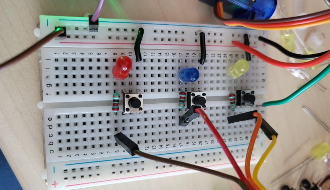
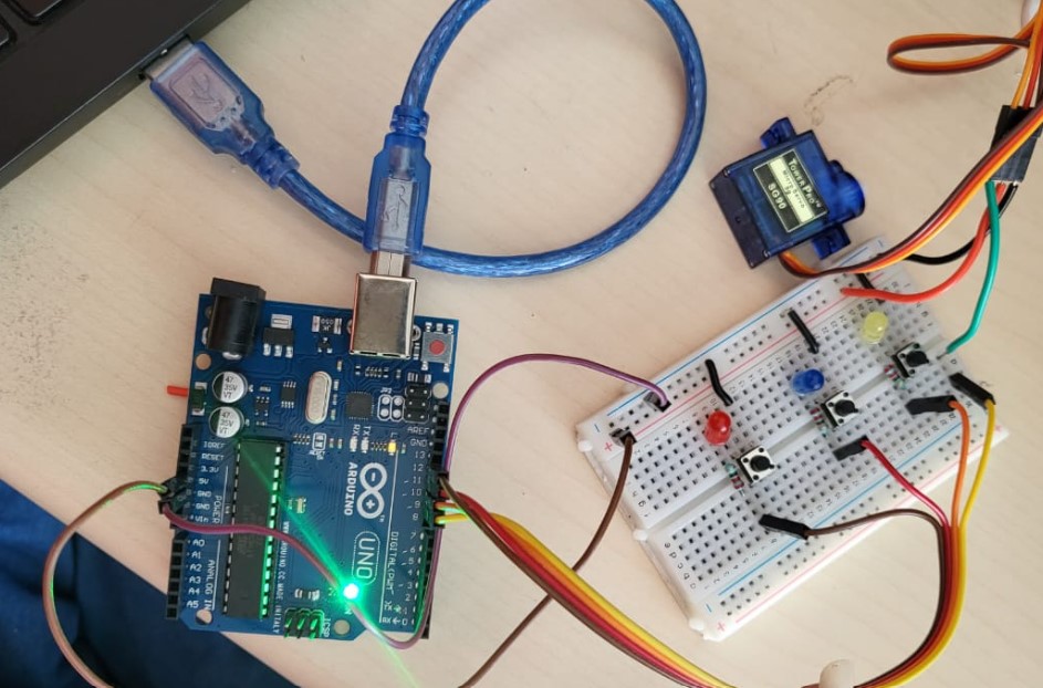
The electronics prototyped on a breadboard in reality is shown below:
Note: Only few wiring is changed. The digital pins are shuffled.
The working video of the same is as below:
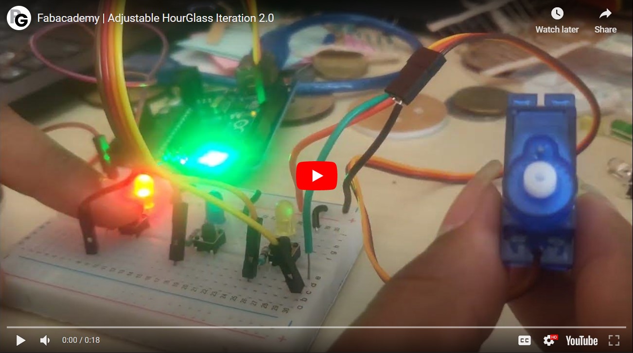
The details of the same can be found in the Final Project page linked.
The code used above is as follows:
        #include <Servo.h>

          Servo myservo;

          int pos = 0;
          const int ledPinRED = 6;
          const int ledPinYELLOW = 7;
          const int ledPinBLUE = 8;

          void setup() {
            myservo.attach(9);
            pinMode(ledPinRED, OUTPUT);
            pinMode(ledPinYELLOW, OUTPUT);
            pinMode(ledPinBLUE, OUTPUT);
          }

          void loop() {
              for (pos = 0; pos <= 180; pos +=1) {
                myservo.write(pos);
                delay(150);
              }
              for (pos = 180; pos >= 0; pos -=1) {
                myservo.write(pos);
                delay(150);
              }
              digitalWrite(ledPinRED, HIGH);
              digitalWrite(ledPinYELLOW, HIGH);
              digitalWrite(ledPinBLUE, HIGH);
          }
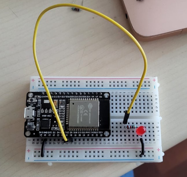
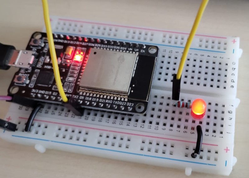
Blinking LED with ESP 32
So I have understood I need to try two different MCU families. SO for that I have written a simple quick LED blinking code with ESP 32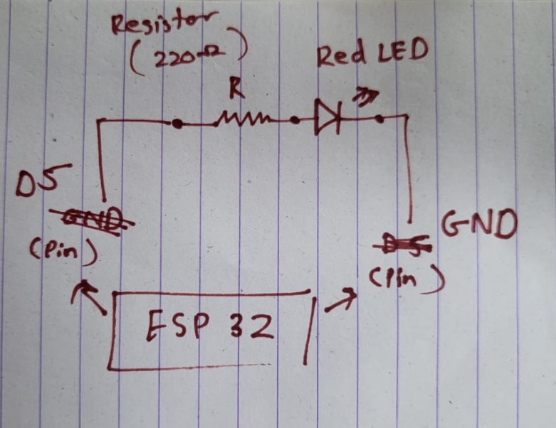
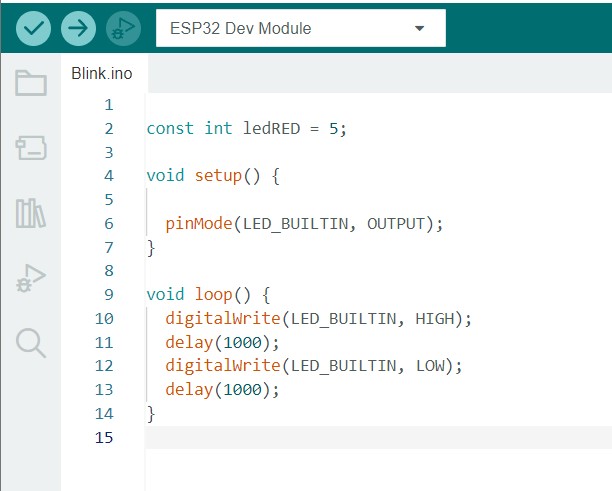
The code for the same is as follows:
const int ledRED = 5;

void setup() {

  pinMode(LED_BUILTIN, OUTPUT);
}

void loop() {
  digitalWrite(LED_BUILTIN, HIGH);
  delay(1000);
  digitalWrite(LED_BUILTIN, LOW);
  delay(1000);
}