11. Input devices♥♡♥♡

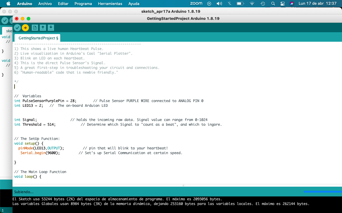
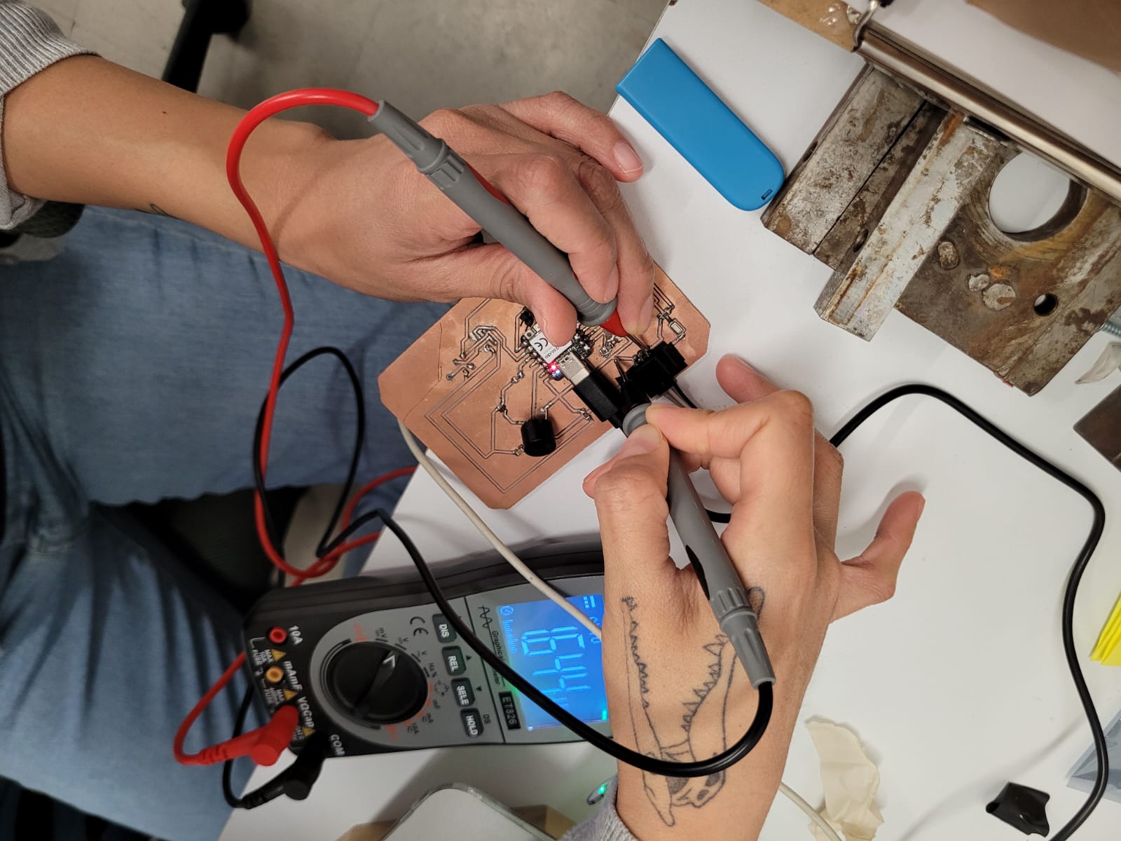
Welcome to "Input devices" week, this time we add a sensor to our PCB we did the last week "Electronics Production".

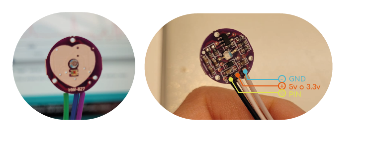
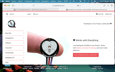
For my project I want to incorporate heart-rate sensors, in order to create an experience of closeness and interaction for the user with their own heartbeat.

Arduino

This sensor measures the heart rate, it is used to easily incorporate data into any project. The current consumption is low, being 4mA with a 5v supply. It is build with a emitting LED and also a intensity receiving sensor. The amount of light reflected by the finger bloodstream defines the output of the sensor, and it is possible to recover data from it.

On the provider's website you can find tutorials on how to install the library and "examples" with different tasks to use in Arduino.

Library

In order to install the library of the sensor, i went to: Sketch > Include Library > Manage Library. Then i look for "pulsesensor" and proceed to install it.

First part

This library have many "examples" for uses with the sensor. At this point i just used the "Getting Started Proyect" code. To experiment with it, i use an Arduino PCB and i put in place the indicated pines.

Arduino PCB

I follow the provider tutorials to make the first activation code from a blue led connected to an arduino plate.

Xiao

I started my programming on the Xiao microcontroller. Tools-> Board-> Boards Manager. Then i select the lastest version of "Raspberry Pi Pico/RP2040"; And finally i just needed to select the port. After this, i modified the code to play it with my PCB schematics.

To check the heart rate in Arduino, i went to: Tools -> Serial Plotter.

Readings

The program have the following instruction: "// If the signal is above "550", then "turn-on Arduino's on-Board LED" but in my signal, the pulse was above 530, therefore i modify the signal to make it act with 514, making easier to turn on the LED.

I was inspired by this tutorial, it helped me a lot.


//  Variables
int PulseSensorPurplePin = 28;        // Pulse Sensor PURPLE WIRE connected to ANALOG PIN 0
int LED13 = 26;   //  The on-board Arduion LED


int Signal;                // holds the incoming raw data. Signal value can range from 0-1024
int Threshold = 514;            // Determine which Signal to "count as a beat", and which to ingore.


// The SetUp Function:
void setup() {
  pinMode(LED13,OUTPUT);         // pin that will blink to your heartbeat!
   Serial.begin(9600);         // Set's up Serial Communication at certain speed.

}

// The Main Loop Function
void loop() {

  Signal = analogRead(PulseSensorPurplePin);  // Read the PulseSensor's value.
                                              // Assign this value to the "Signal" variable.

   Serial.println(Signal);                    // Send the Signal value to Serial Plotter.


   if(Signal > Threshold){                          // If the signal is above "550", then "turn-on" Arduino's on-Board LED.
     digitalWrite(LED13,HIGH);
   } else {
     digitalWrite(LED13,LOW);                //  Else, the sigal must be below "550", so "turn-off" this LED.
   }


delay(10);


}


♥♥♥♥

I had to modify my pins to make it compatible with my Xiaorp2040. I also have to cover the sensor to avoid any other ligth.

Buzzer

I change the pin in order to turn on the speaker with a tone.

Sound


    //  Variables
    int PulseSensorPurplePin = 28;        // Pulse Sensor PURPLE WIRE connected to ANALOG PIN 0
    int LED13 = 26;   //  The on-board Arduion LED
    
    
    int Signal;                // holds the incoming raw data. Signal value can range from 0-1024
    int Threshold = 514;            // Determine which Signal to "count as a beat", and which to ingore.
    
    
    // The SetUp Function:
    void setup() {
      pinMode(LED13,OUTPUT);         // pin that will blink to your heartbeat!
      pinMode(4, OUTPUT);
       Serial.begin(9600);         // Set's up Serial Communication at certain speed.
    
    }
    
    // The Main Loop Function
    void loop() {
    
      Signal = analogRead(PulseSensorPurplePin);  // Read the PulseSensor's value.
                                                  // Assign this value to the "Signal" variable.
    
       Serial.println(Signal);                    // Send the Signal value to Serial Plotter.
    
    
       if(Signal > Threshold){                          // If the signal is above "550", then "turn-on" Arduino's on-Board LED.
         digitalWrite(LED13,HIGH);
       } else {
         digitalWrite(LED13,LOW);                //  Else, the sigal must be below "550", so "turn-off" this LED.
       }
       
       
         tone(9,130,81);
    
    
    delay(10);
    
    
    }


Downloadable files.

Power

Take out the power consumption, (the power will be the product of the voltage to which it is connected (V) and the intensity of the current that passes through it (I), result P=V*I.

In the reading it gave me was the following: 1.6v and 2 mA.

So the power is 1.6x0.002=0.0032w. In conclusion, the power of my sensor is relatively low compared to other devices and some components of my colleagues.

Again I am excited to see how the program is loaded into the microcontroller, it is like a victory, this emotion is new.

Contact me

dimaricruzchavez Linkedin