9. Output devices

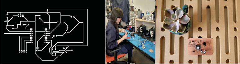
Welcome to electronic Production week, the goal of this assignment is to learn more about elecetronic desgn and programing them to perform task. I will use the boards I built during the week of electronic production and electronic design. In this area so unknown to me, I am very grateful for the help of my partner and now instructor Fábell.

Tinkercad:

Users can begin with a starter circuit or build their own. Virtual-circuits are a great way to learn and tinker before. https://www.tinkercad.com/

Neopixel

“NeoPixel” is Adafruit’s brand for individually-addressable RGB color pixels and strips based on the WS2812, WS2811 and SK6812 LED/drivers, using a single-wire control protocol.

NeoPixels don’t just light up on their own; they require a microcontroller (such as Arduino) and some programming. We provide some sample code to get you started. To create your own effects and animation, you’ll need some programming practice. If this is a new experience, work through some of the beginning Arduino tutorials to get a feel for the language.

These have 3 pins: +5v, GND and Din-Do, the latter is the input and output of the data pin.

Neopixel Programing

I started by programming the neopixel to turn on and off, first integrating the Adafruit library: https://learn.adafruit.com/adafruit-neopixel-uberguide/arduino-library-use

More Programing

Then I included in my programming a buzzer that turned on together with the neopixel. Lastly, I added a button and a red led, the latter turned on when I pressed the button.

Play

I incorporated several elements into one program, I was proud, but it was the easy part.

Xiao

I downloaded my board again to start my programming on the Xiao microcontroller. Tools-> Board-> Boards Manager. Select the lastest version of "Raspberry Pi Pico/RP2040" and install it; And finally select the plate and the port.

Editing my pins for Xiao

When I transferred the code I made in Tinkercad to my Arduino software I had to modify my pins to make it compatible with my Xiaorp2040.

:(

When changing my pins, I had failures, in this attempt I only turned on my NeoPixel.

:)

This time I managed to get the programmed tone done.


    #include Adafruit_NeoPixel.h //add the <> symbols
        int boton1 = 0;
        int controlPin =8;
        Adafruit_NeoPixel NP1 = Adafruit_NeoPixel( 1, controlPin + NEO_KHZ800);
        void setup()
        {
        NP1.begin();
        pinMode(1, INPUT);
        pinMode(0, OUTPUT);
        pinMode(9, OUTPUT);
        }


        void loop()
        {
          boton1 = digitalRead(1);
          if (boton1 == 1) {
            digitalWrite(0, HIGH);
          } else {
           digitalWrite(0, LOW);
          }
                       
          NP1.setPixelColor(0, NP1.Color (56 , 4 , 209));
          NP1.show();


          tone(9,130,81);
          
          
          delay(1000);
          NP1.clear();
          NP1.show();
          
          delay(1000);
        
        }


Power

For the neopixel measurement, I used a program for a strip of 4 neopixels with a "rainbow" effect, where the program divides the # neopixels and assigns each neopixel a rainbow color.

In the code you can see the command: pixels.rainbow where I put 4 numbers, these are: (1) the # of times to divide the neopixels so that pressing 1=all neopixels; (225) is the saturation, the 255 is the max; (100) is the intensity of the color, (Consumption: Maximum 60 mA per led, 20 mA for each internal led, White at maximum intensity), here you can vary the intensity, an average consumption of 100 works for me.

In the next part I share the code for the 4 neopixel strip with the rainbow effect.


            #include Adafruit_NeoPixel.h> //add <>
                #ifdef __AVR__
                #include avr/power.h> // Required for 16 MHz Adafruit Trinket
                #endif
                #define PIN 2 // Definir pIN de salida
                #define NUMPIXELS 4  // Cuántos neopixels?
                
                
                Adafruit_NeoPixel pixels(NUMPIXELS, PIN, NEO_GRB + NEO_KHZ800);
                
                #define DELAYVAL 500 // Time (en milisegundos) to pause between pixels
                
                void setup() {
                
                
                #if defined(__AVR_ATtiny85__) && (F_CPU == 16000000)
                  clock_prescale_set(clock_div_1);
                #endif
                  // END of Trinket-specific code.
                
                  pixels.begin(); // INITIALIZE NeoPixel strip object (REQUIRED)
                }
                
                void loop() {
                  pixels.clear();
                     pixels.rainbow (0,1,255,100);
                     pixels.show();
                
                  
                }


Take out the power consumption, (the power will be the product of the voltage to which it is connected (V) and the intensity of the current that passes through it (I), result P=V*I.

as a result I got a low value of 2.01 mA for every neopixel with good neopixel illumination.

# Neopixels V I P
4 5.10v 8.10mA 41.31mW

This week I was excited by the programs I was able to do, it took me a lot to get used to the requirements of each step, but with practice the steps will be more intuitive.

Contact me

dimaricruzchavez Linkedin