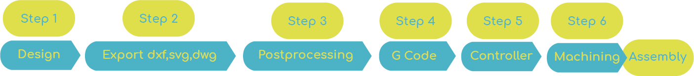
7. Computer controlled machining
In this week I work in a Router CNC, this sistem is a manufacturing method that automates the control, movement and precision of machine tools through the use of G code preprogrammed, which is embedded inside the tools.
The machine I worked on is an ASIA ROBOTICA that has a power of 4 or 6HP at 24,000 rpm. Its work area is 1.22 x 2.44m, and a precision of +/- 0.15 mm.
Test
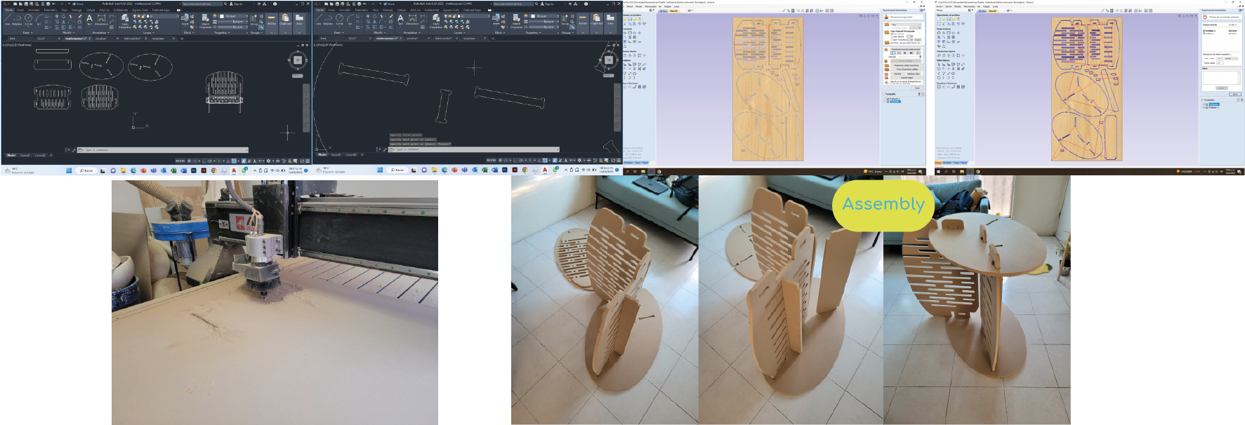
For my tests I made a pattern and an assembly in AutoCAD. Save the file in DXF and open the file in V CARVE program to do G code programming.

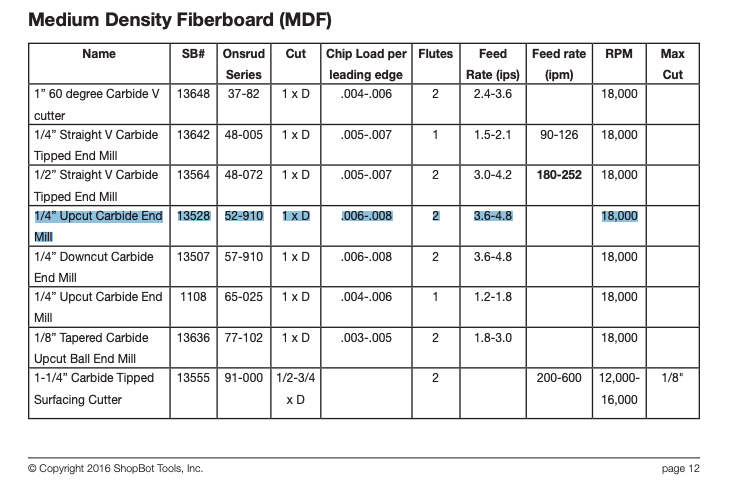
Data for cutting MDF with a 1/4 endmill
For the MDF cutting, i found the table provided by Shopbot in the Feeds and Speeds Charts document.
Amana tools has the Chip load per tooth properties to calculate the Feed rate of our tool setup (200ipm/0.0058" chip load per thoot).

Required machining parameters.
In the database of the tool, the program to generate the G code will ask you for the following information.
| Properties | Description | Supplier | Resultado |
|---|---|---|---|
| Machine | CNC | ASIA ROBOTICA | max 24000 RPM |
| Material | MDF | - | 15mm |
| Diameter | Tool diameter | End mill 1/4" max RPM 28000, 2 flutes | D=0.25 inch |
| Depth of pass | How much does the tool cut per pass? | It is specified by the tool supplier, or 50% of the Ø of the tool. | 0.125 inch |
| Stepover | Distance that the tool has between each pass. | Depends on the application | 40% in bas reliefs |
| Spindle speed | How fast is the spindle going to turn? | As per the reccomendation table | 18000 rpm |
| Feed rate | Feed per tooth or Chip Load | As per the reccomendation Amana tools/ or Chip load x rpm x # flute | 200 ipm = 5075.98 mm/min |
| Plunge Rate | Forward speed | Depends on your process and material | To start I use 800 mm/min |
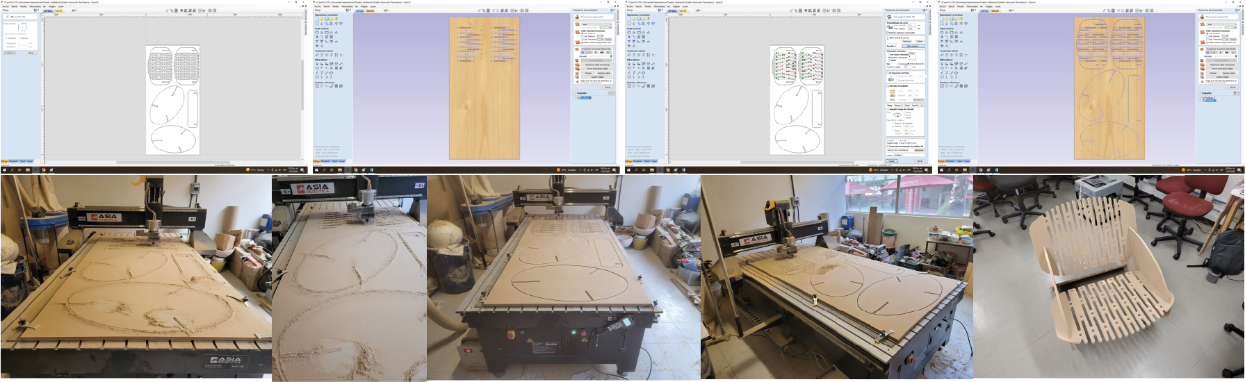
V CARVE
VCarve allows to create an 3D or 2D carving from a file.
To use Vcarve, first you open Vcarve. Then you choose the measurements of your material and your zero piece.
In interface controls, you will be able to modify the position, restore or edit your file.

On the left side of the program you can find the "Toolpath operation", first you select your internal vectors and use the "2D profile toolpath" (for cutting through the material).
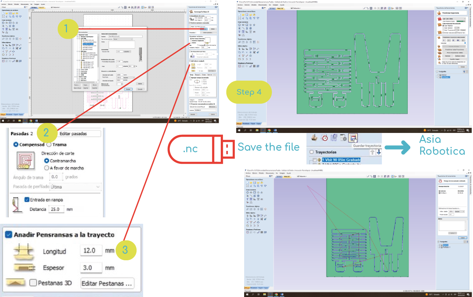
In the first module, it asks us for the depth of cut, I only indicated the final depth of 15.3mm, because I wanted to cut with an extra range of 0.3mm, but, I don't care because I use a 9mm sacrificial table.
1. In the next module you can add your tool by creating a new profile, I used the following parameters for my end mill of 1/4", 2 flute: D=0.25 inch, Depth of pass= 0.125 inch, stepover= 40%, spindle speed=18000 rpm, feed rate= 5075 mm/min and piunge rate= 800 mm/min.
2. In passes, it is recommended not to exceed the r of your tool, if my tool drops 15.3 mm by placing 5 passes on it, this bar will 3.08mm.
Here I can also indicate if the cut is inside or outside, I made 2 profiling files, 1- for the inside profile that will cut my internal lines. and another 2-on the outside for my outer cut.
3.In this module I add tabs, so that my outer cut doesn't move when I'm about to finish the same cut (12x3mm).
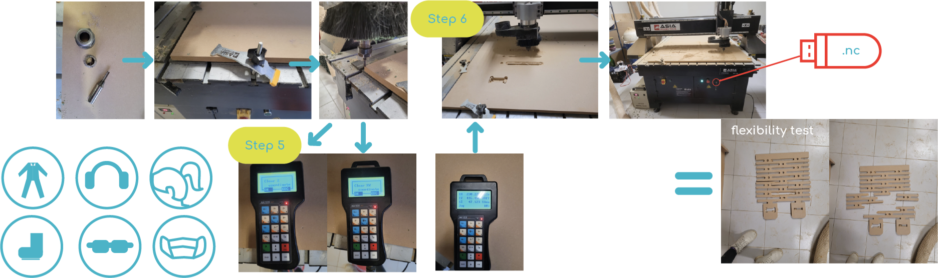
Step 4, I save my file in the Asia Robotica postprocessor and it generates my G code with the ending .nc.
Security measures
When using a CNC machine, it is necessary to consider accident prevention, for which constant training and two rubles of safety equipment are needed: 1) Equipment control or 2) The safety of the strainers.
1) The first aid kit, eye wash, emergency exits and existents are necessary.
2) For personal use: Protection glasses, ear plugs, non-slip metallic toed shoes and gloves to handle the material face coverings, tie your hair and wear appropriate clothing.

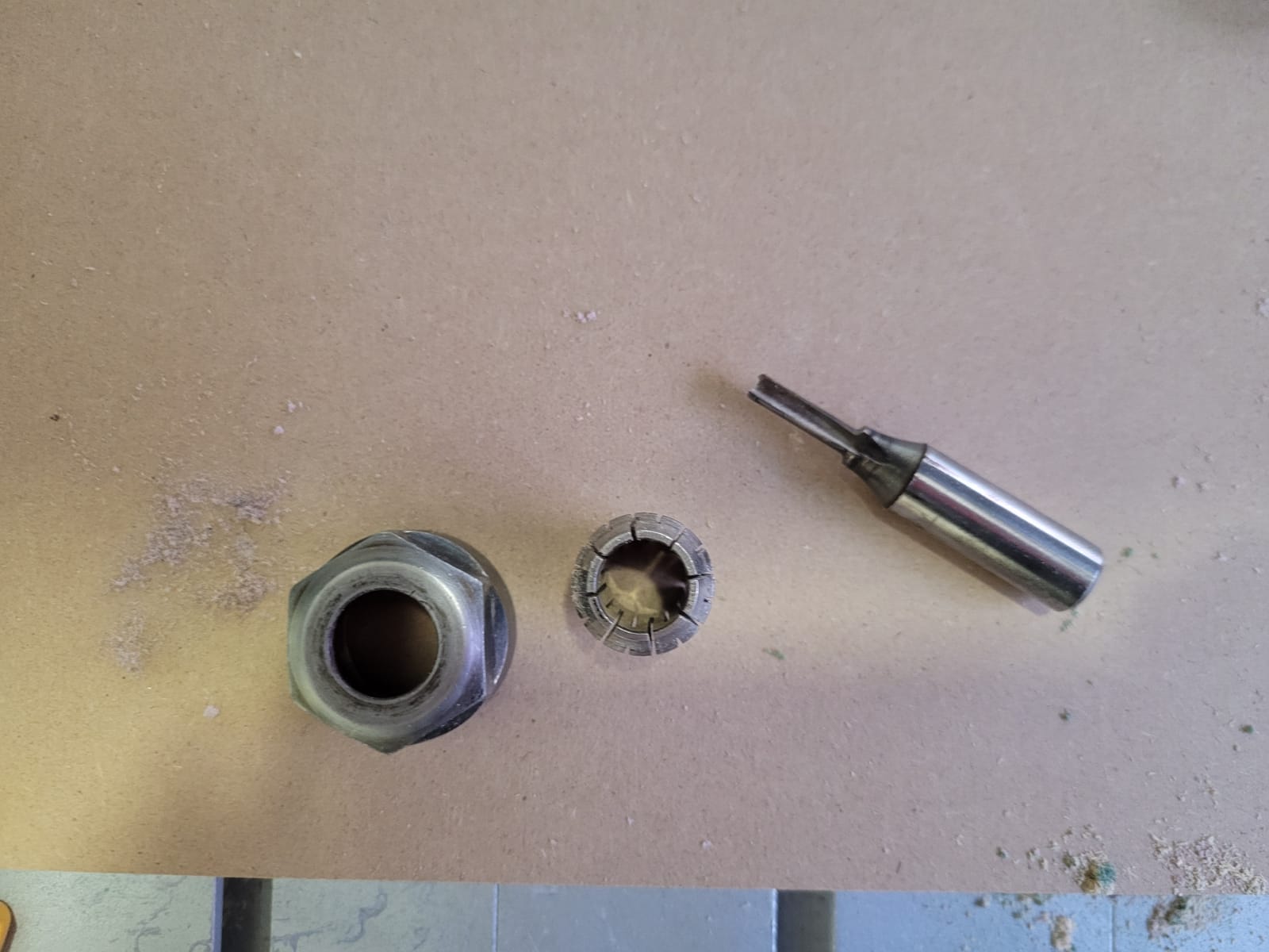
This is the cutter that I use, it is 1/4".
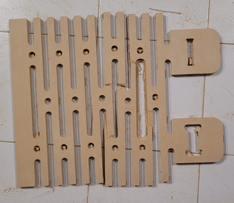
Flexibility test
Taking into account the security measures, I carried out the first test, at the end the result was that flexibility could be achieved in the material (MDF-15mm) and that my gap between assemblies was too much, so I decided to lower it to a size of 0.3mm.
Test
With this test I also saw that the cut was not exact, I measured it and it had an excess of 1.5mm towards the interior, so you must consider that the cuts should be 1.5 looser per side in MDF.
I also tried 2 types of size in the assembly, it is important that your internal cuts have this excess that you see in the image, because with the rounding of the cutter it will leave a rounding and will not fit your piece. Just slightly going over the thickness works, so it's not too showy either.
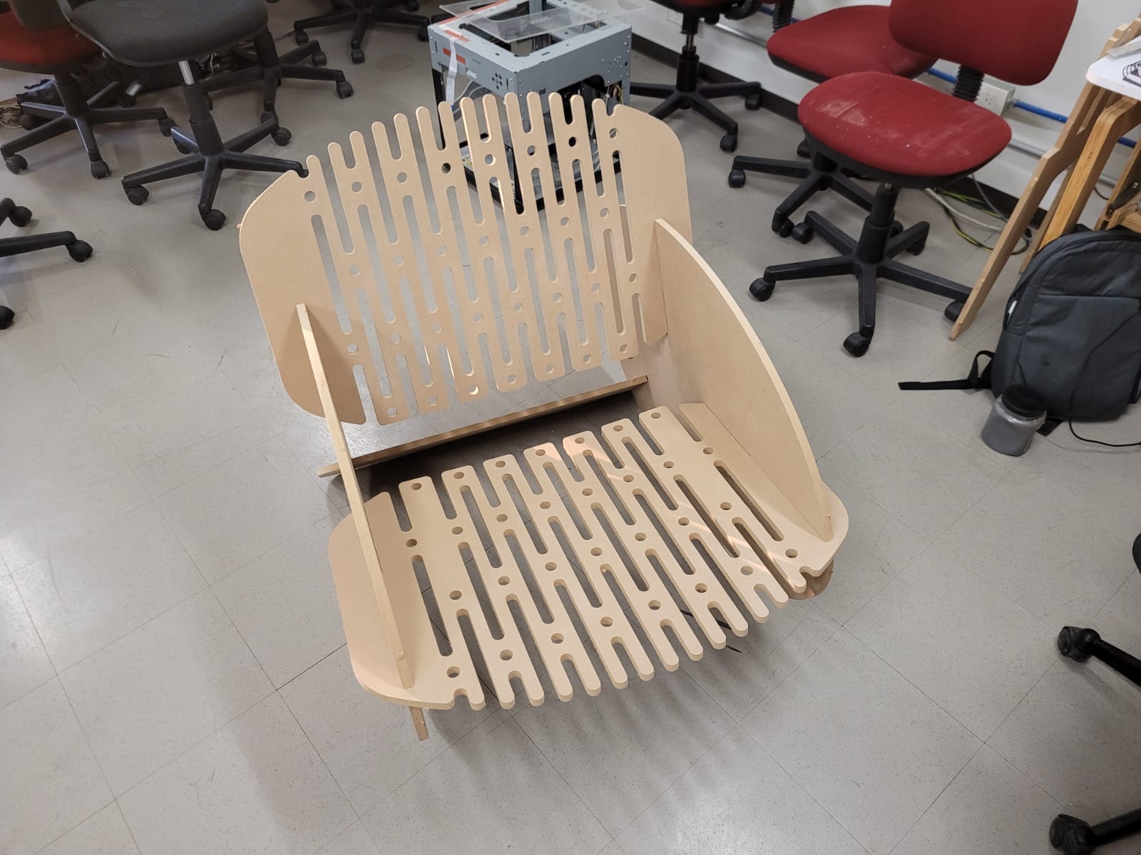
First cut
Inspired by: CHAIR
To make the design of my chair I used the global variables that solid has, to add the range of 1.5mm of looseness (in assemblies) and also the thickness of my material of 15mm. Then I exported my DWG file to open it in AutoCAD to check the vectors, if any vector is open, you can use the "join" command by typing it in the command bar to close vectors, then save the file as: AutoCadR12/LT2( *dxf).
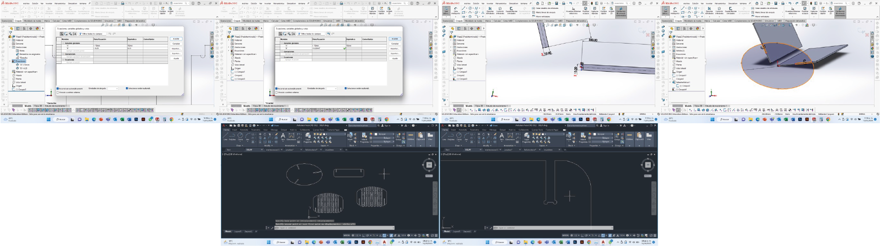
Too much flexibility
In this first attempt, the chair began to break when someone tried to sit down.
In my first design I chose not to do internal assemblies, but this is not so good, because the assemblies don't structure properly. In this test I corroborated that the assemblies must be internal if you want a better result.
In this test the assemblies worked with the looseness of 1.5mm, but structurally they are too easy to disassemble when moving the chair.
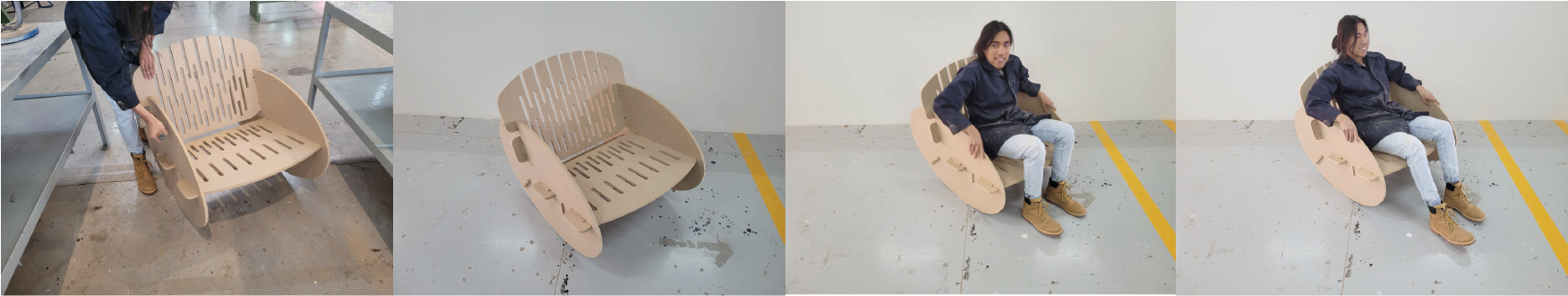
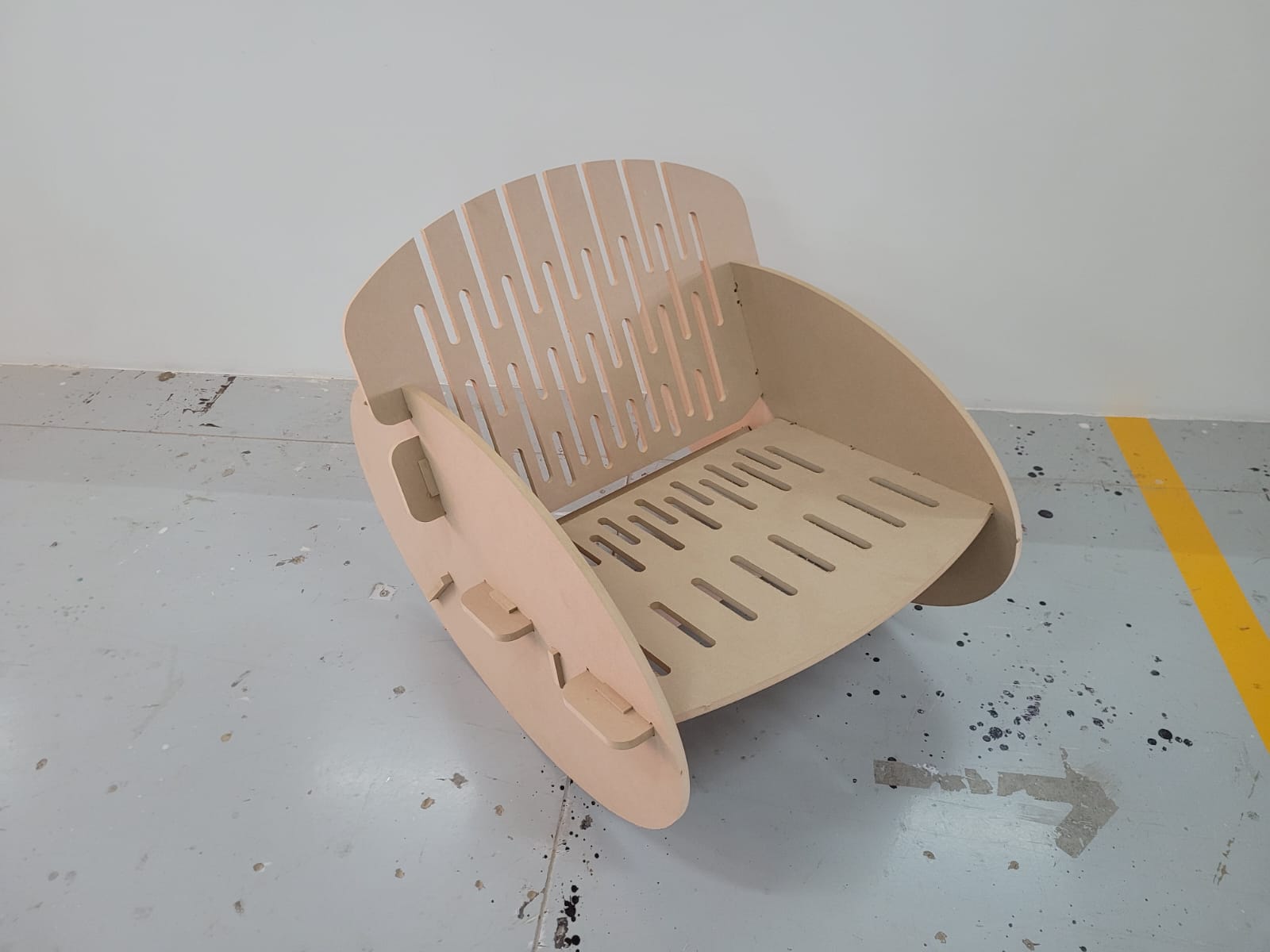
Final
In this attempt, the assembly was made more resistant, making closed assemblies and that only the back of the chair had a little flexibility.
:)
In this proposal, the assemblies are internal and have padlocks to prevent them from coming out, the 1.5mm clearance becomes 3mm because they are internal and it works quite well.
File to download
This week I find it quite interesting and fun, for every week you take into account the time.