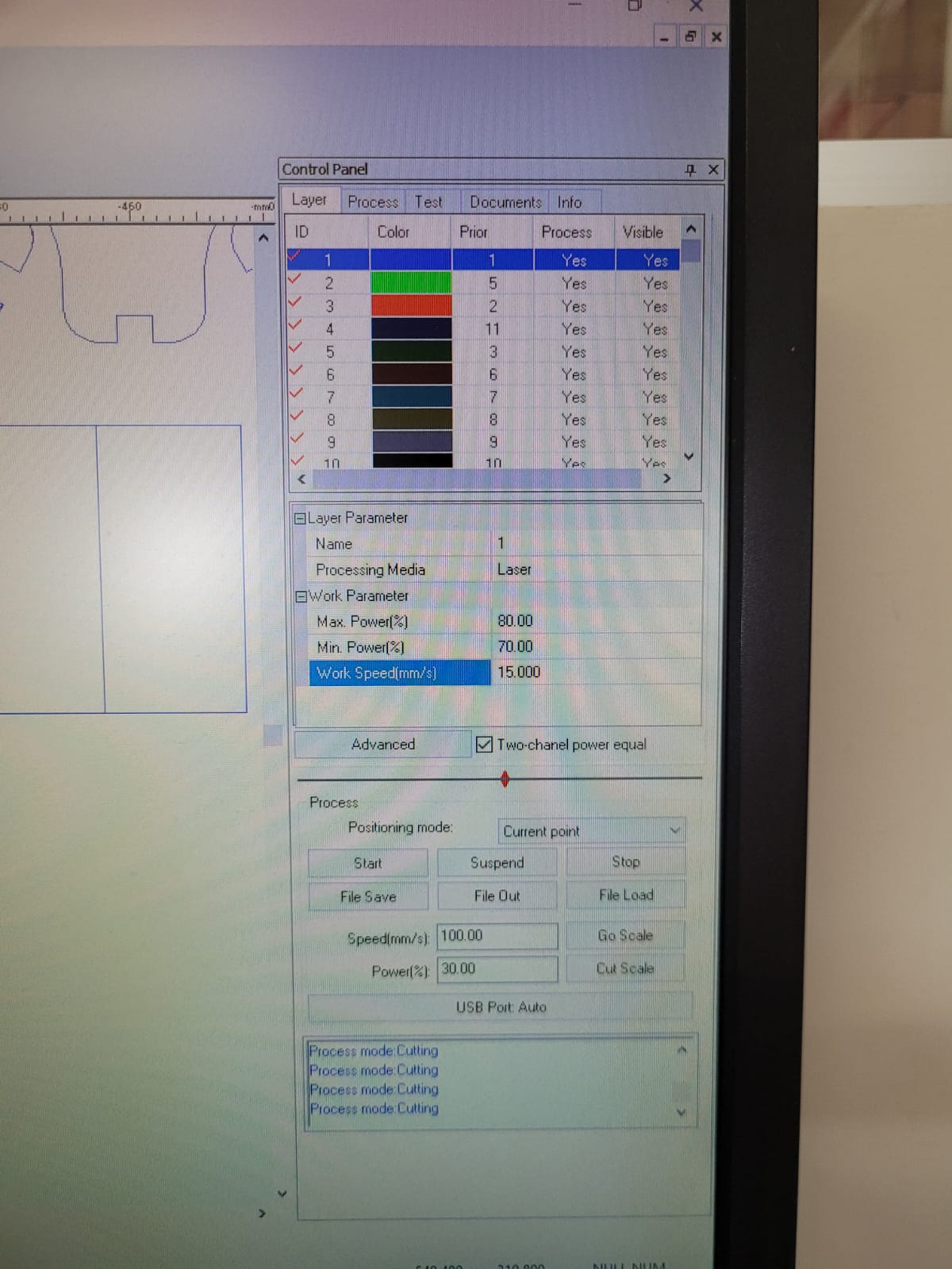
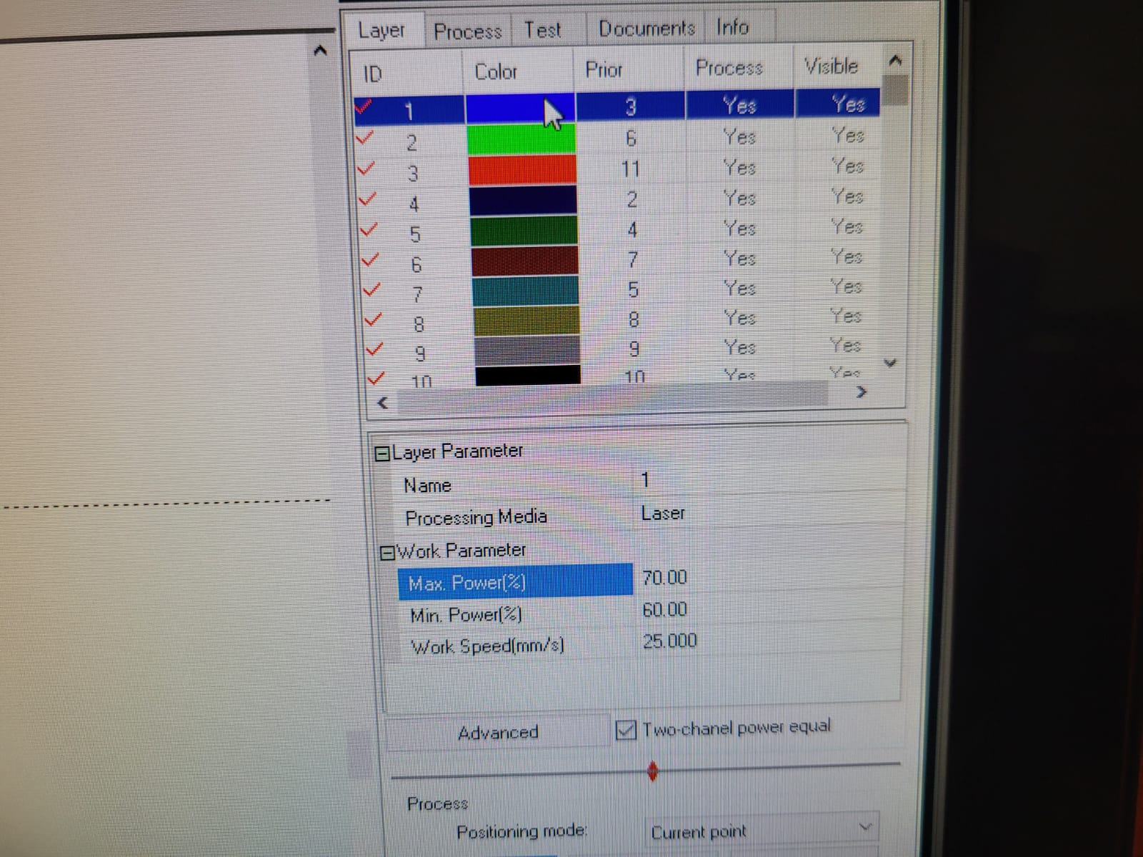
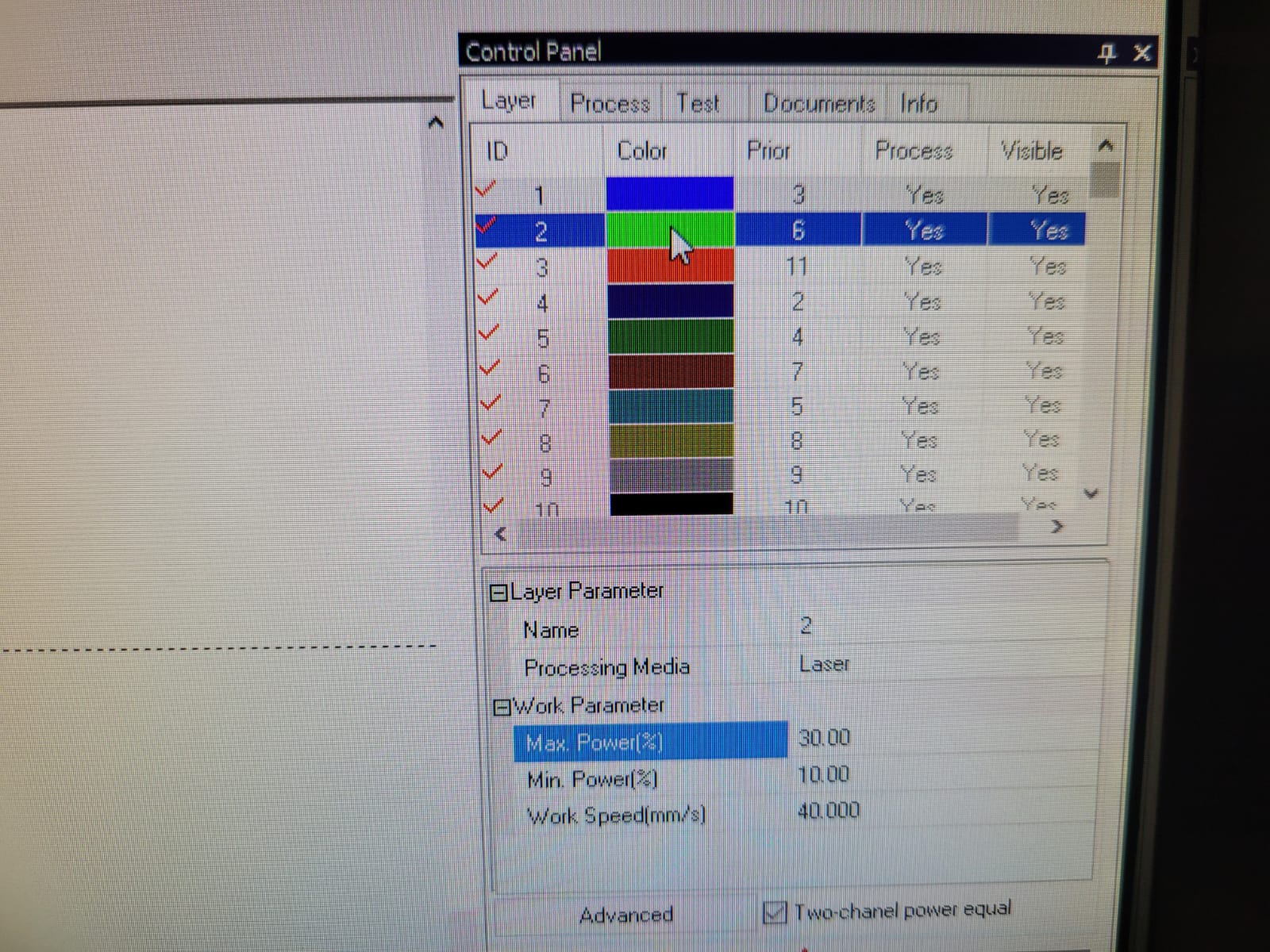
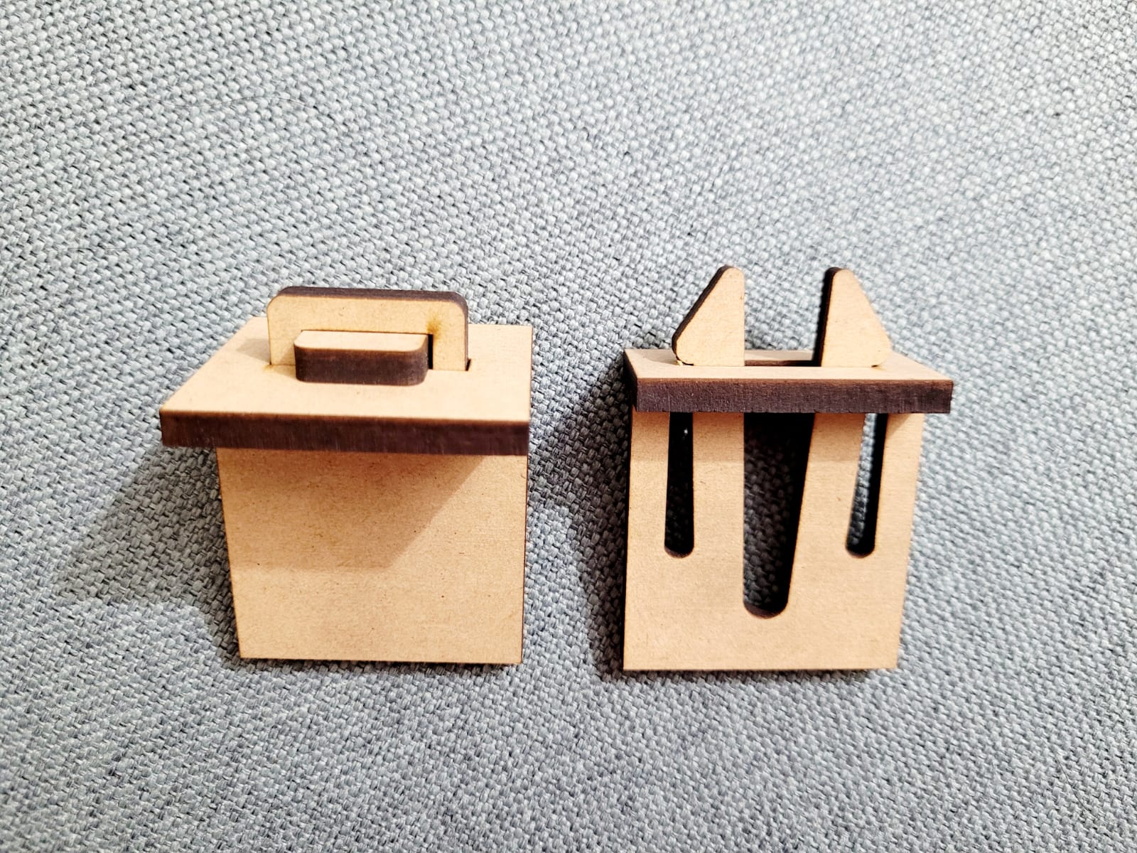
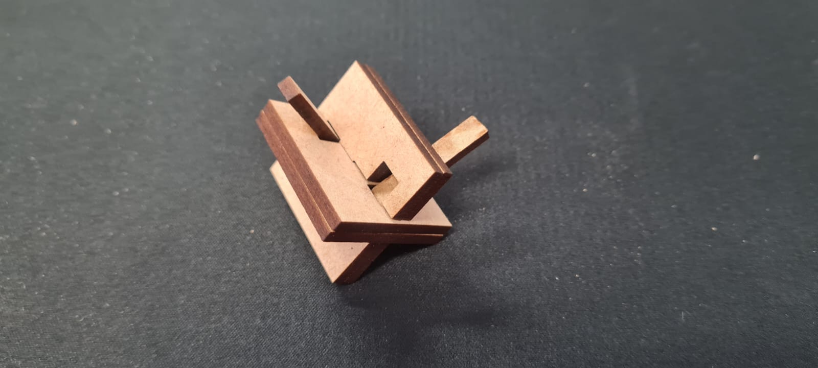
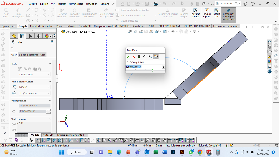
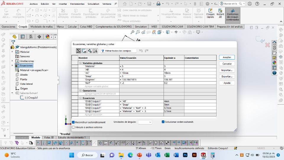
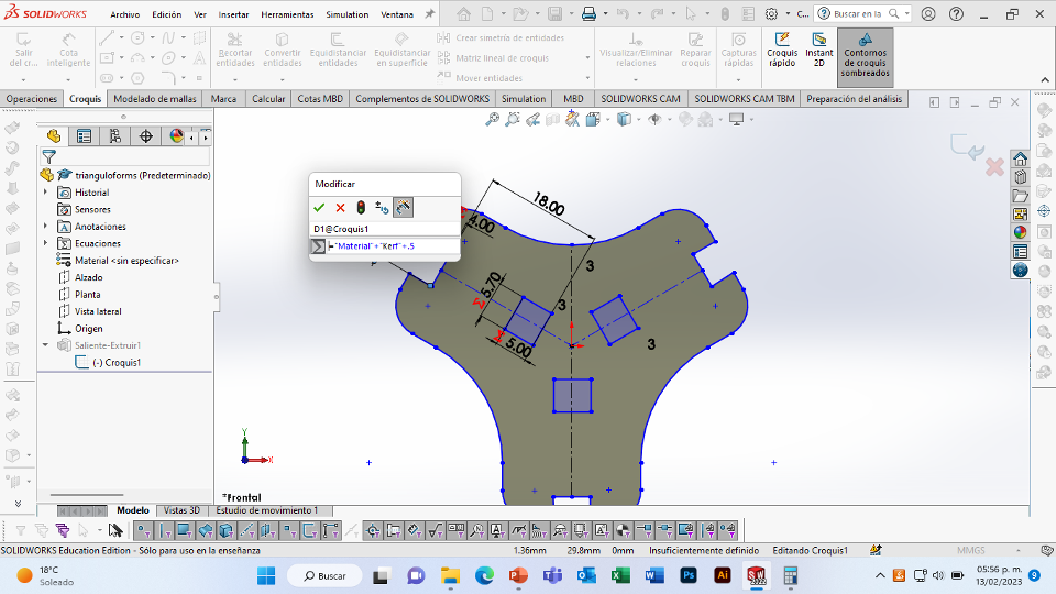
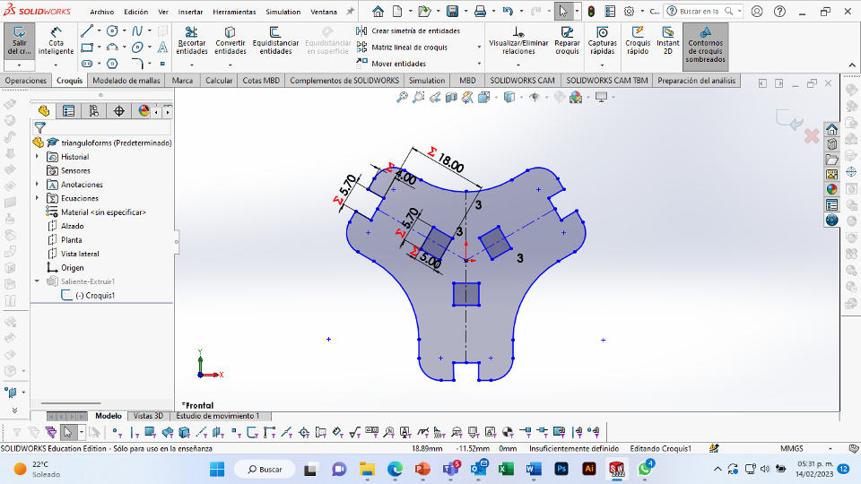
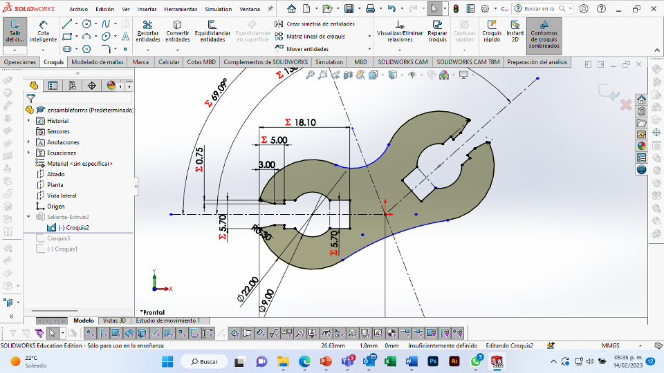
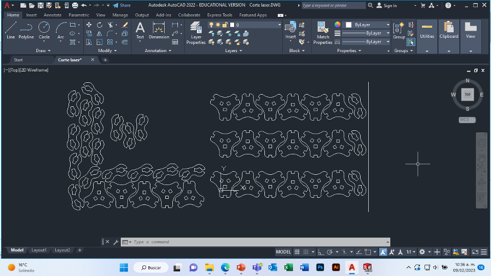
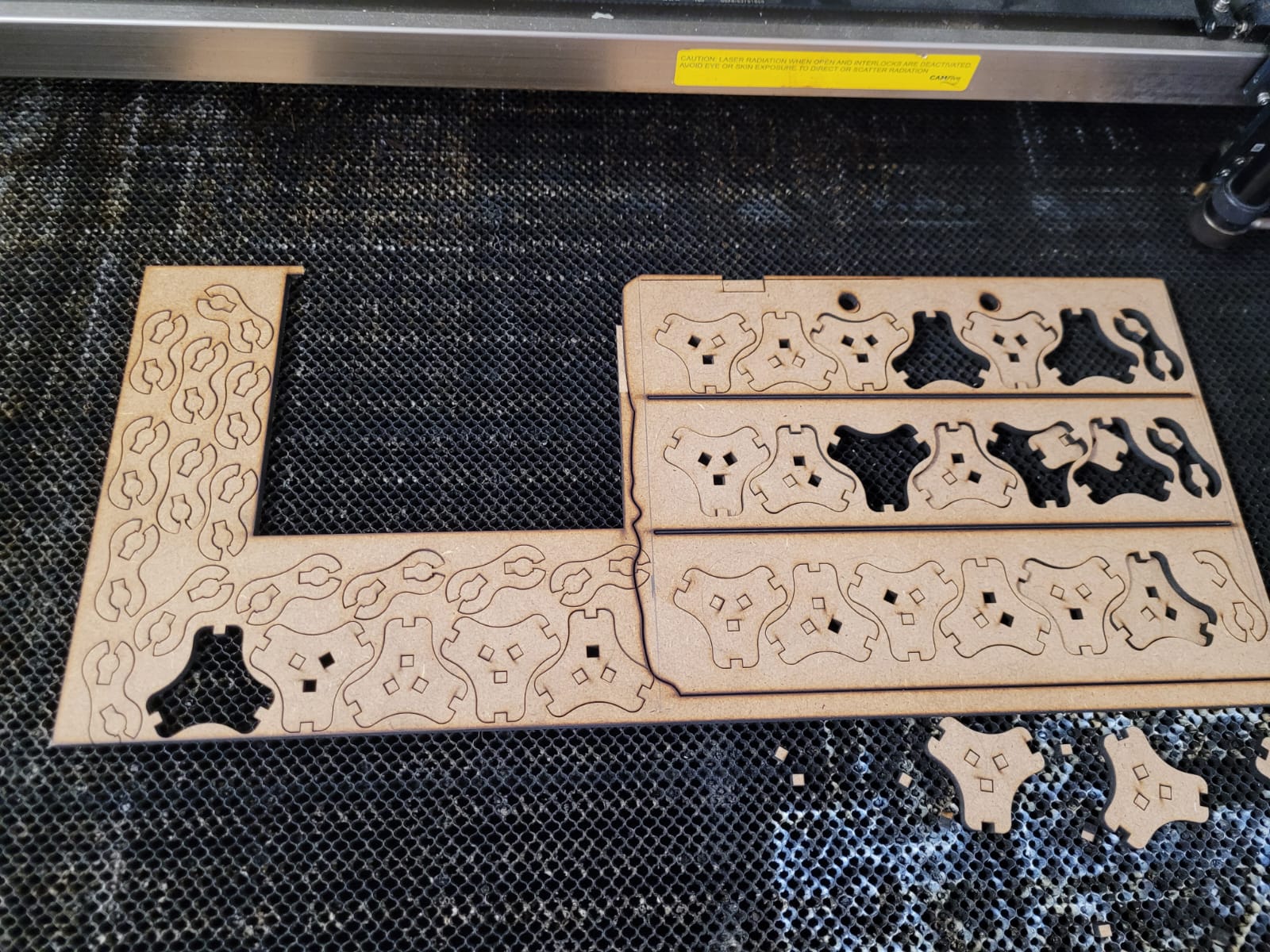
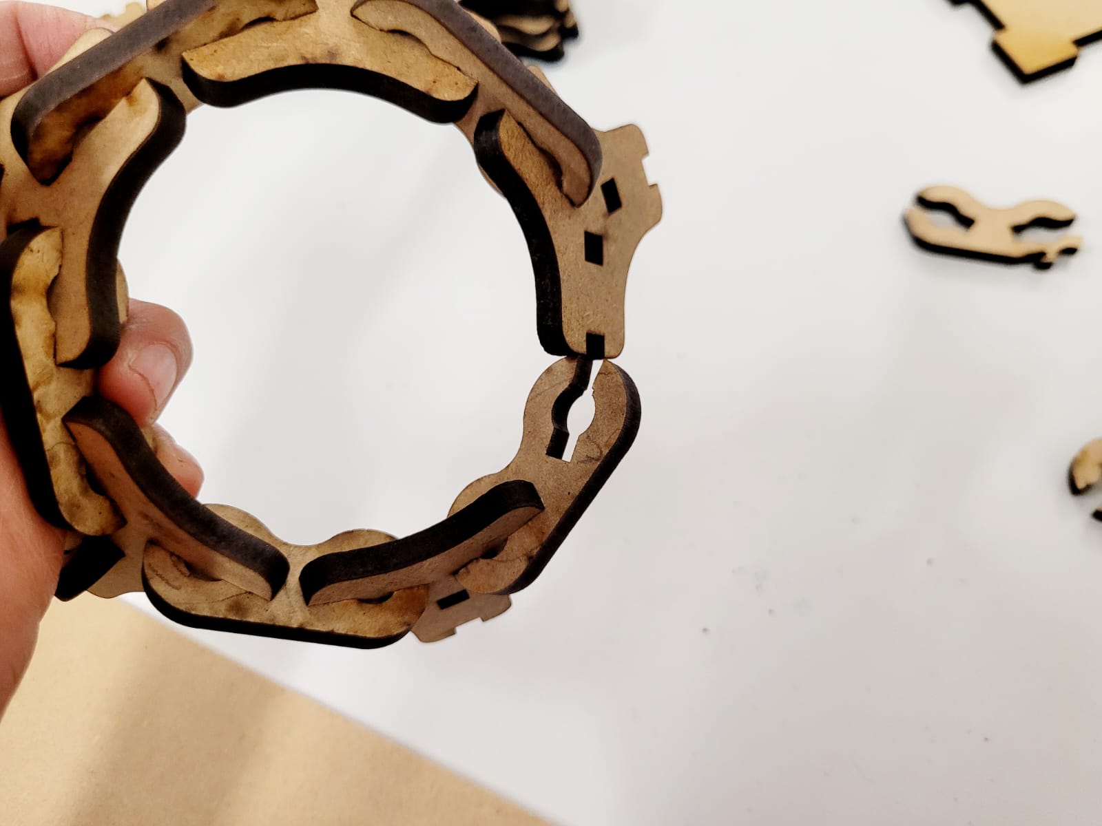
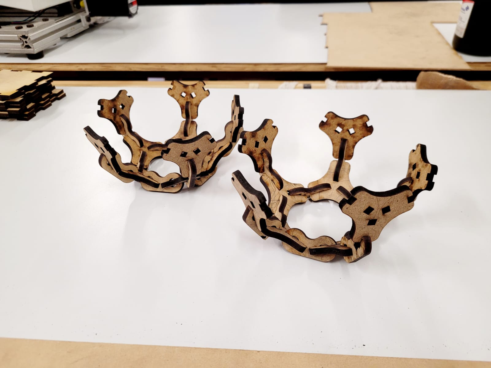
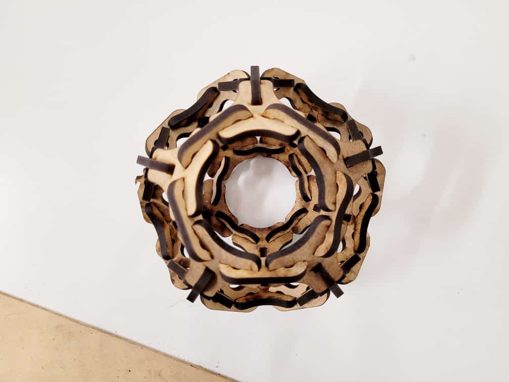
3.Computer Controlled Cutting

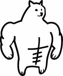
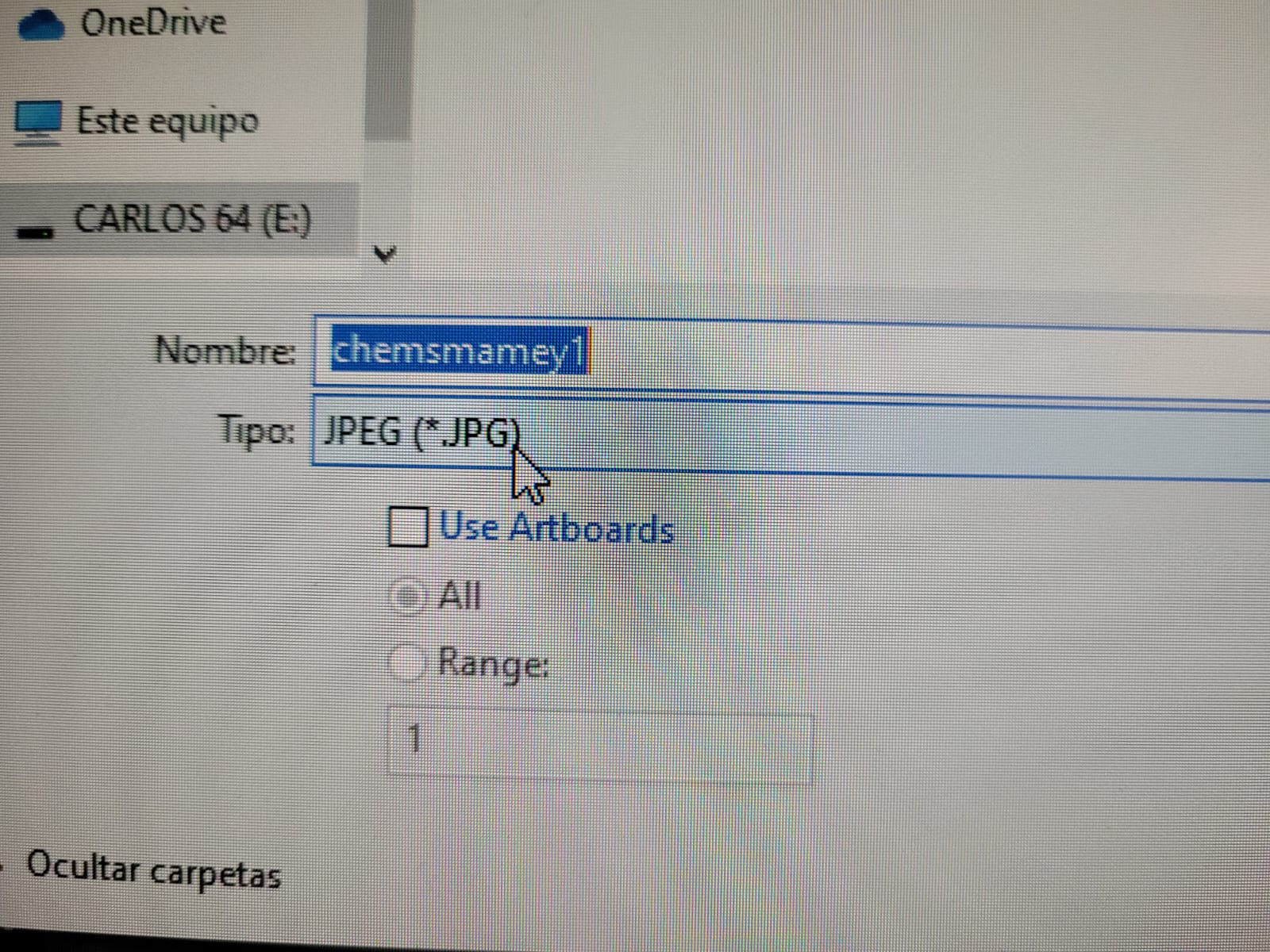
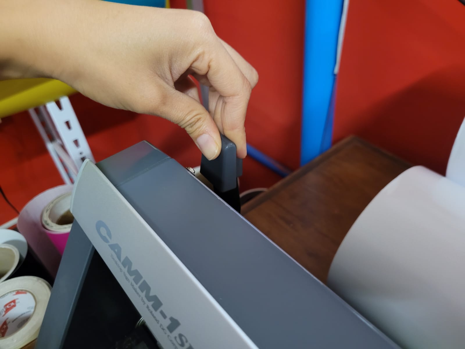
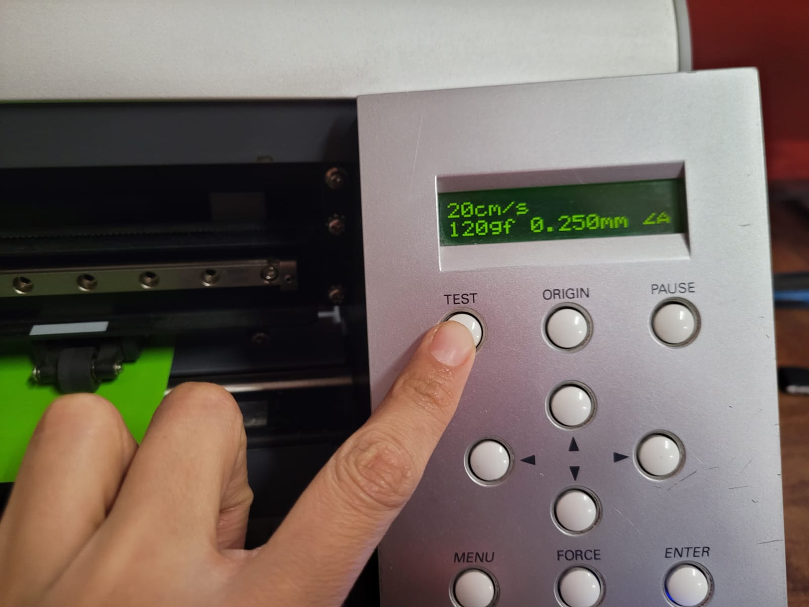
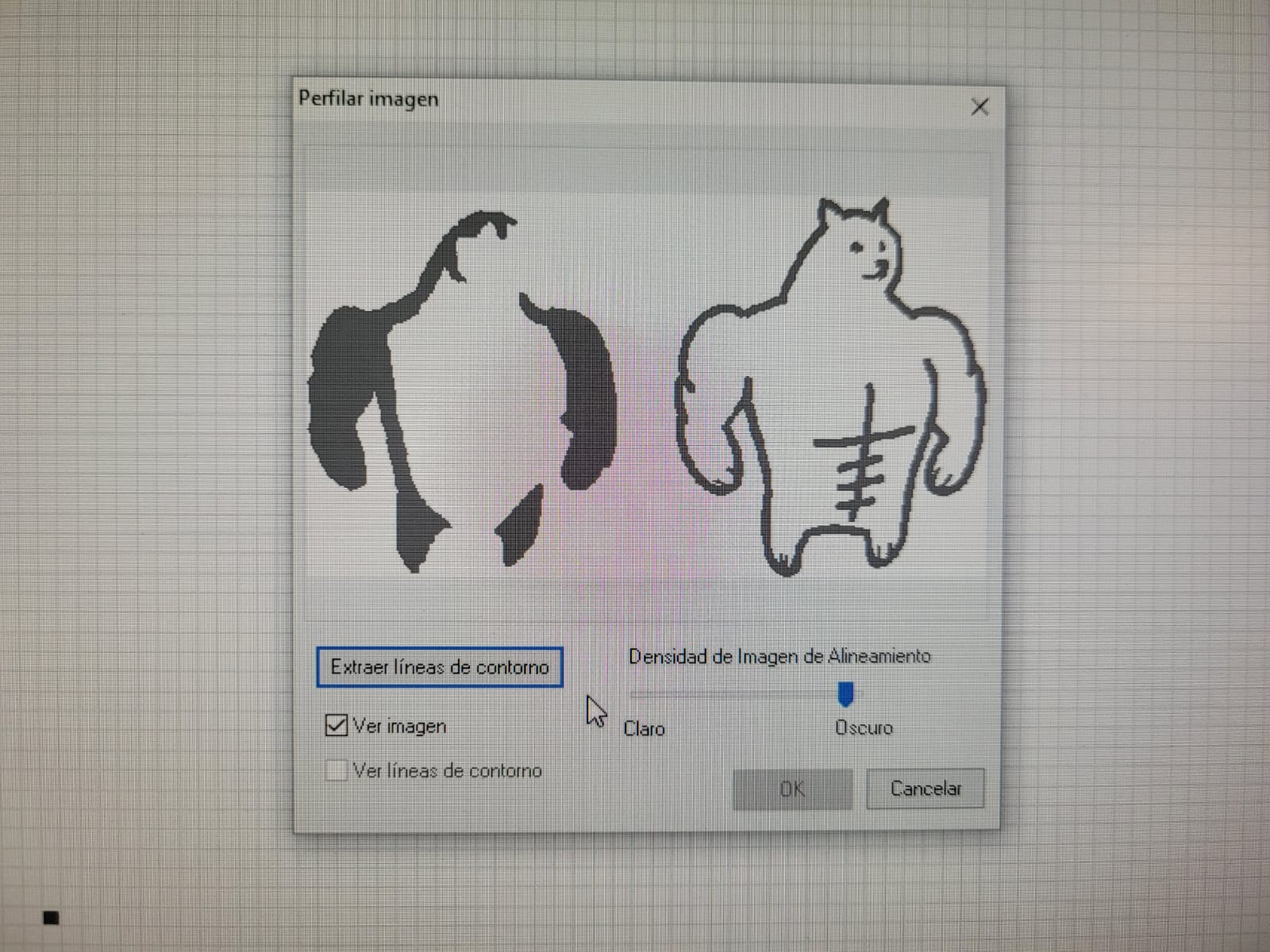
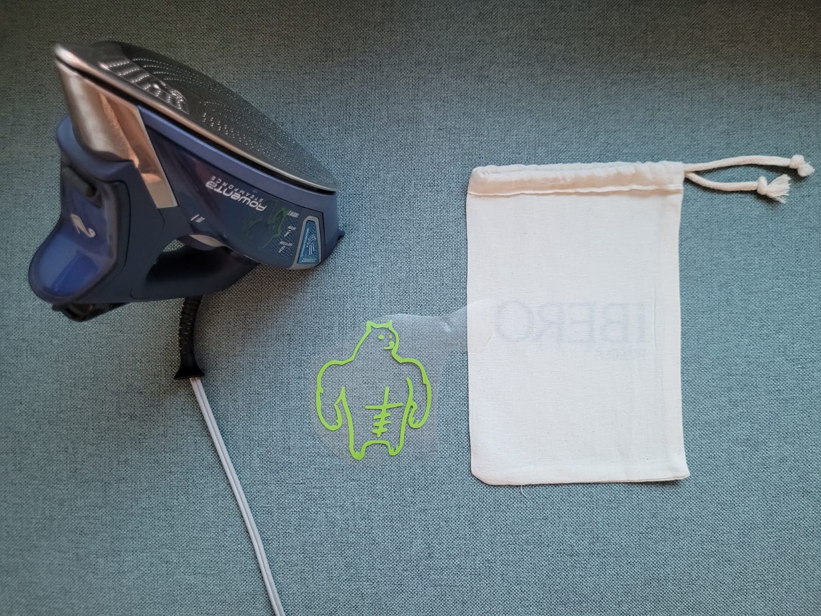
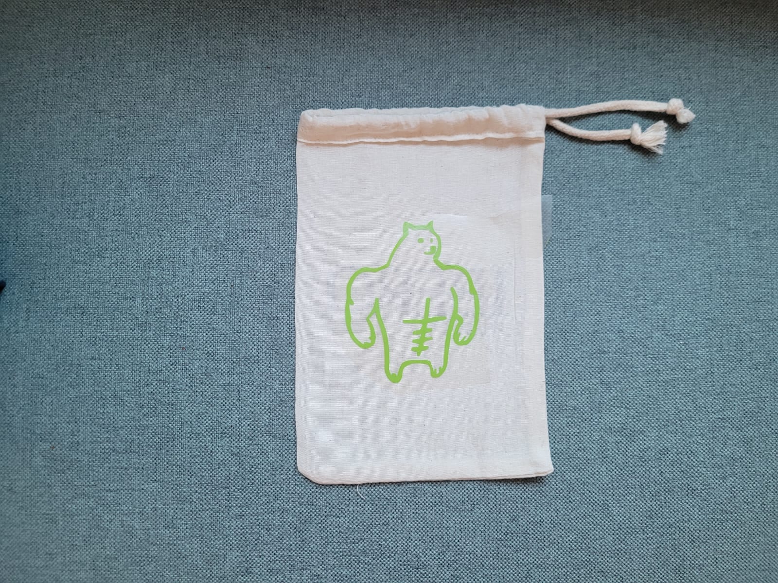
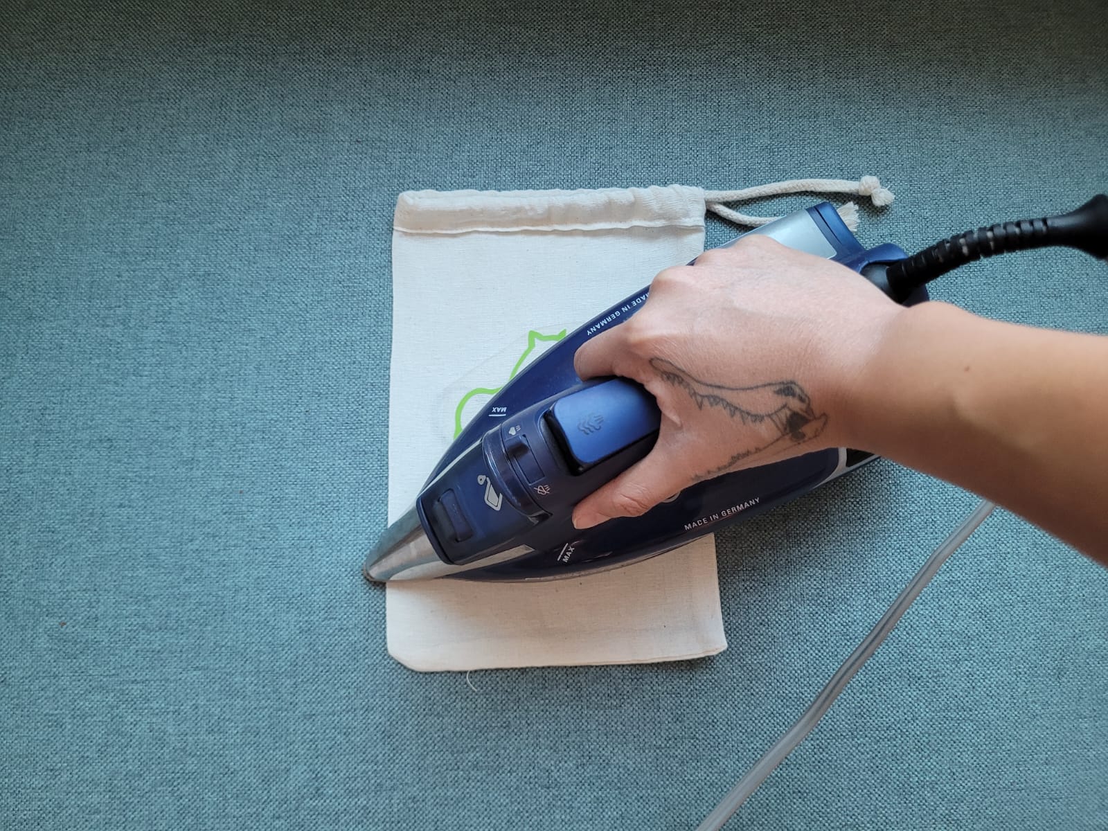
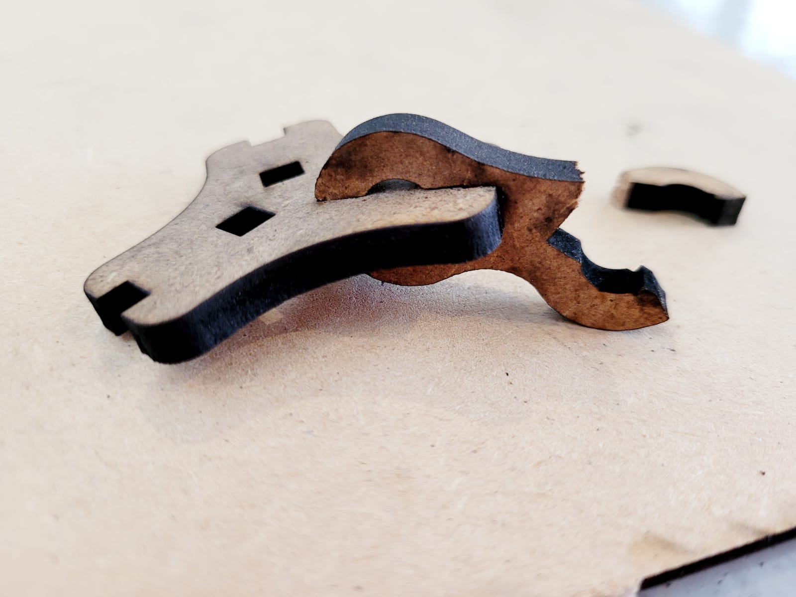
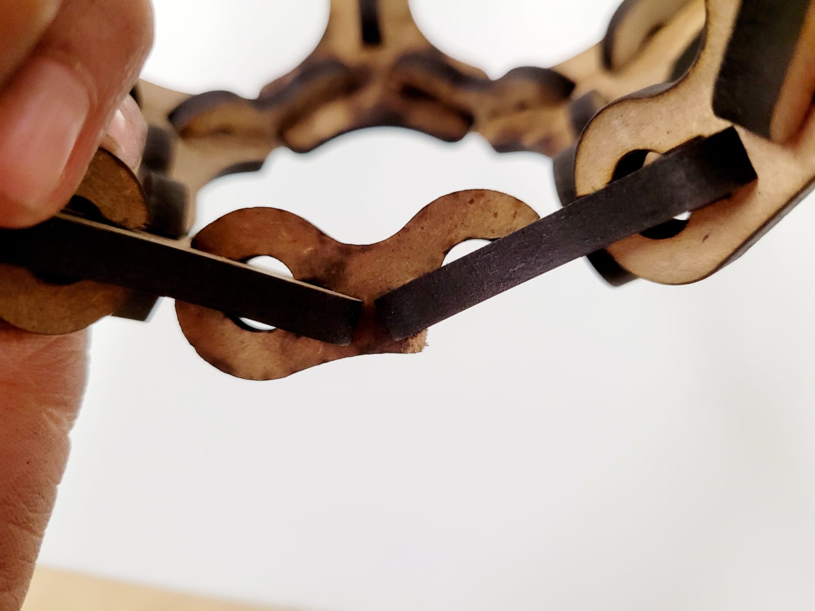
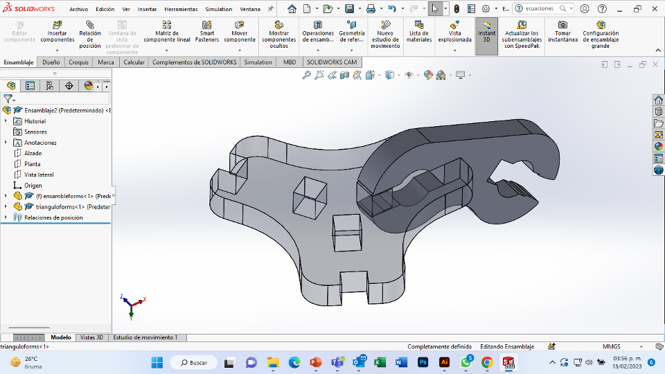
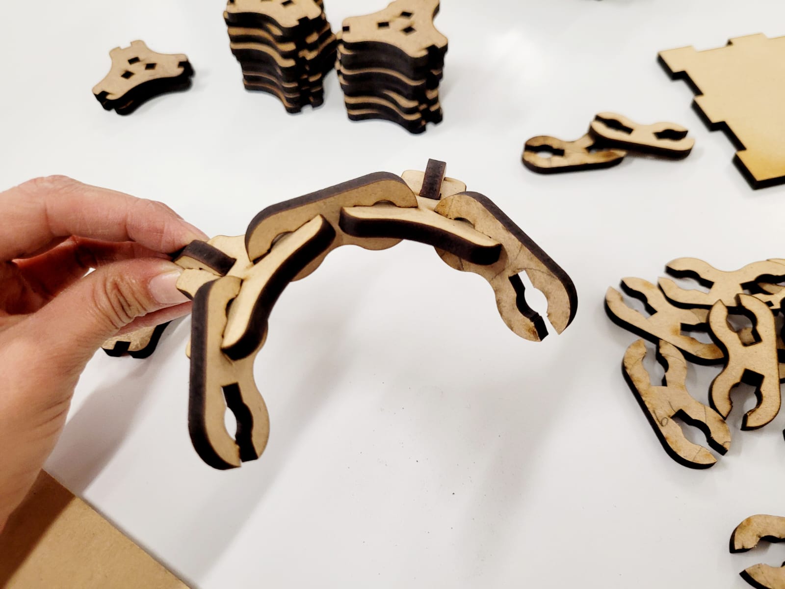
For this week we did the characterization of the laser cutting machine, we designed a parametric equipment that can be attached using only with your own sets. We also did a vinyl cutting exercise. Cutting machines are a tool used in a wide range of industries for precision cutting and designing projects.

800px

Vynil

I chose vynil for textiles to do my assignment. I started by doing my design in the Illustrator program, which is not a free program, but you can request a 7-day free trial. I use the brush tool to draw a "strong chems" that comes out of a well-known "meme" of a puppy.

1. First I raised the clamping lever of the cutting machine, I ajust my vynil with the help of the machine rollers, then I lowered the lever and hit "Enter" so the cutter would slide close of the roller and show me the place where I should start my cut.

2. Set the force and test it to see if it cut enough (20cm/s 120gf 0.25mm). Then i just export my drawing in the format of “jpg” as an image.

3. For the cut I used the cutting program called Roland Cut Studio (it is a software that is not free to use, but it is compatible with the cutters of the same brand), I opened the program and imported my image.

4. With the mouse right click, i select the option “sharpen image” to edit the image density and extract the contour lines.

5. Separate the image from the created lines and delete my image.

6. With the "Cut" option, i executed the cutting.

7. To remove my vynil tube I had to raise the lever and turn off the machine, *In my first cut, the vinyl had to be cut on the opposite side, so I repeated the same process but now with the white part facing up.

The material that I used to place my vynil was a small bag of raw blanket.

1. First remove excess vinyl and trim it for application.

2. This vinyl does not need a transfer, because it adheres with heat, the transparent part helps us keep the vinyl tidy and isolated from direct contact with the iron.

3. Then i place the vinyl with the transparent side up and apply heat with my iron.

4. Finally i remove the transparent protector and I'm ready.

LASER

Laser cutting is a digital fabrication process, Laser cutting is mainly a thermal process in which a focused laser beam is used to melt material in an specific area.

Speaking of characterization for the laser cutting machine, i experiment with the laser power and the cutting speed. I perform my Kerf test and the design assembles with respect to this test. The material I used was 5 mm MDF, but for my parametric design this was one of the parameters that I would change with respect to thickness.

characterization

Each machine (CAM five) has its own parameters and sofware (Smart Carve), such as the nominal power, this machine use a 90 watt CO2 cutting. Other variations to consider are the type of material and his thickness.

to make this, first i start with the blur parameter, in the machine I use 5mm apart from the focal length.

The material that I used was 3 and 5 mm MDF, I started doing different ranges of speed and power for my project.

Work as a team to experiment with the laser cutting process. We experimented with different cutting speed and power ranges to come up with one that was powerful enough to cut through the material but not too powerful to burn the material.

Cut

Material Thickness Max. Power % Min. Power % Work Speed (mm/s)
MDF 3 70 60 25
MDF 5 80 70 15

Engraved

Material Thickness Max. Power % Min. Power % Work Speed (mm/s)
MDF 3 & 5 30 10 40

Cutting method

To calculate the Kerf, is the width of material that is removed by a cutting process, our instructor Oliver taught us this technique, which consists of making a rectangle with different lines, then measuring the excess space and dividing it by the number of lines.

The best cutting parameters were chosen.

The space measures 1.2mm, I divided it between the 6 lines, the result was 0.2mm which is laser roughing.

Ensembles

Our team experimented with different ensembles, the ones that interested me the most were those of Sanap and Wedge.

As a result of comparison the assembles, I decided that the internal assemblies are more difficult to disassemble, also the simple ones can be applied to tasks of covers or elements that are going to be removed several times.

Module

This process helped me to verify the assembly of the pieces that I had previously modeled in 3D and to know its implications.

In my previous 3D modeling, I formed the truncated icosahedron with 142.62° between the polygonal faces of the pentagon and the hexagon; From this modeling i take the angle of the polygonal faces between each hexagon, which was 138.18 °.
For the parametric design, I entered the thickness of the material in the formula table, in this case 5mm MDF, my distances that I wanted in my assembly, the degrees and the Kerf.

Drawing

i start an sketch from a top plane, drawing the shape of the module and its joints with the connector piece. For my assembly distance, I use the sum of material thickness +Kerf+clearance (0.5mm). Then with the “extrude” tool, I created a solid with the thickness of the material.

Crabs!

For the connector piece I created an sketch from top plan, for its design I was inspired by the claws of a crab.

I used the aforementioned angle to form its main axes, to draw and using the previously "mirror" tool.
Again for assemblies, I use the sum of material thickness +Kerf+clearance (0.5mm). For the Snap, i use a total distance of 1.5mm of padlock. Then with the “extrude” tool, I created a solid with the thickness of the material.

Cut

To make the verification and to export my file in the best way, I use the AutoCAD software (you can request a 30-day free trial), although it is not a free software, it has several versions of DXF that are compatible with most cutting machines. I recommend from experience to export in Auto CAD 2013LT2013DXF(*dxf) and AutoCadR12/LT2(*dxf). I prepared my file in the “Smart Carve” software to cut my pieces in the range that works best for me.

:(

I started to assemble the sphere, but I realized that the assembly did not work, it was difficult to assemble the pieces and ssome of them broke. Also, when finishing assembling the sphere, it is necessary that the last 10 assemblies do not have any straps.

Back

I go back to the program and i change the size of the Snap, now use a total distance of 0.5mm of lock. To the length of the assembly i add 0.1mm of clearance. i also reinforce the area of ​​the piece where it broken. Then with the “extrude” tool, I created a solid with the thickness of the material. Add a second connector piece for the final assembly, these would slide on, so I removed the snap. Using the Solid Works “assembly”, i verify the two parts. In total, there would be 20 modules, 20 connectors with snap and 10 connectors without snap.

Finally

I really liked the result and what I learned. This process helped me to verify the assembly of the pieces that I had previously modeled in 3D and to know its implications.

2D

Downloadable DWG files.

DXF

This week I was able to be more organized than I had been in my previous jobs, I liked my projects.

Contact me

dimaricruzchavez Linkedin