2. Computer Aided design

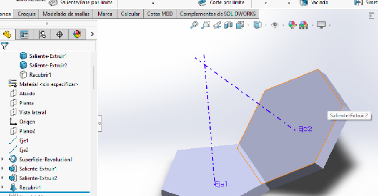
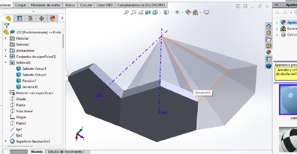
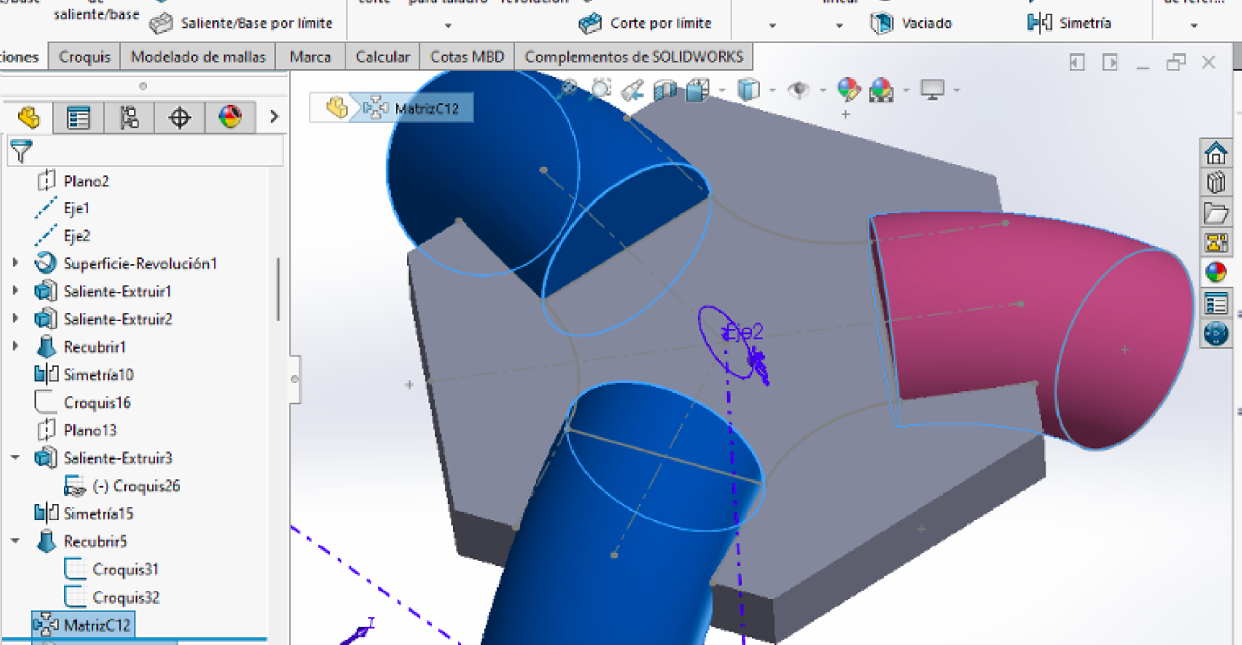
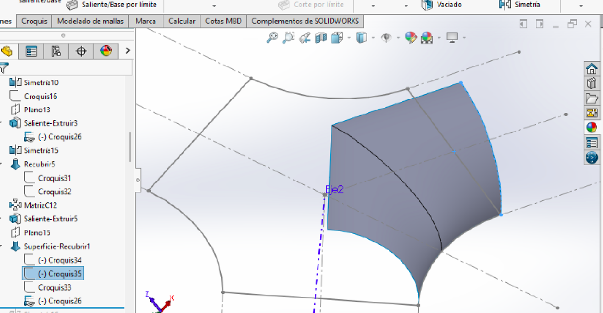
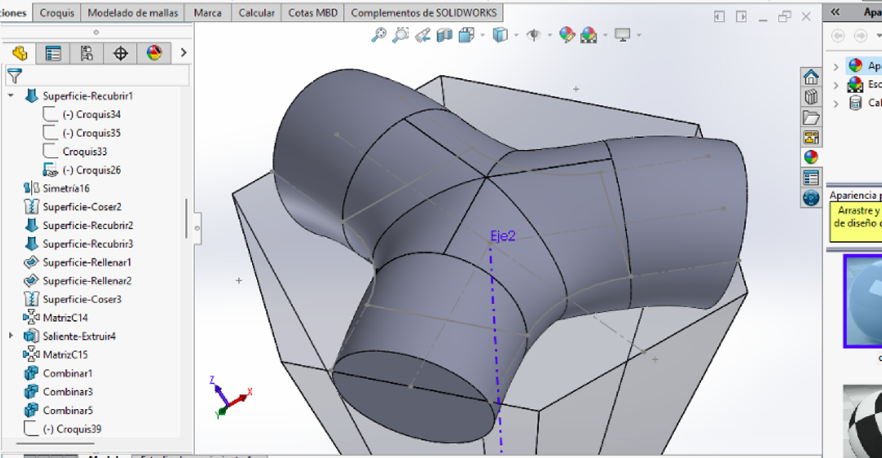
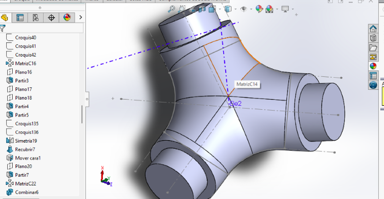
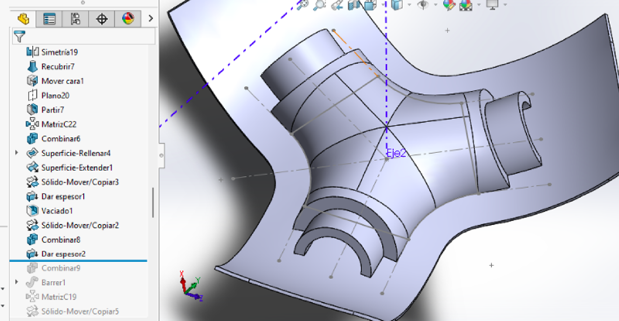
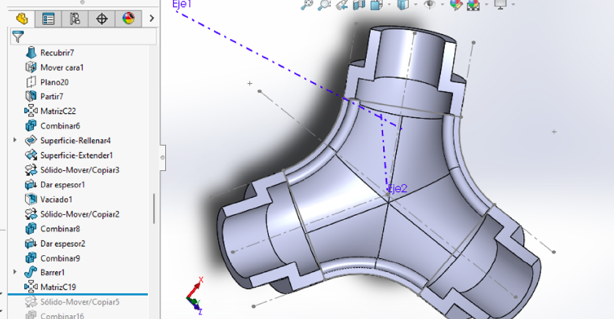
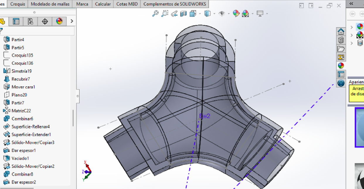
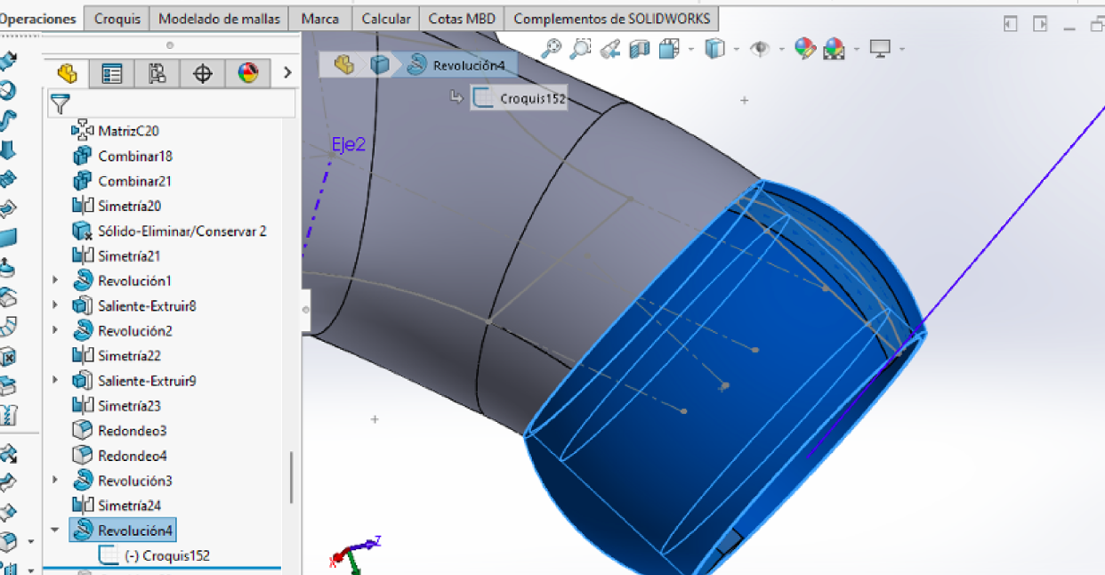
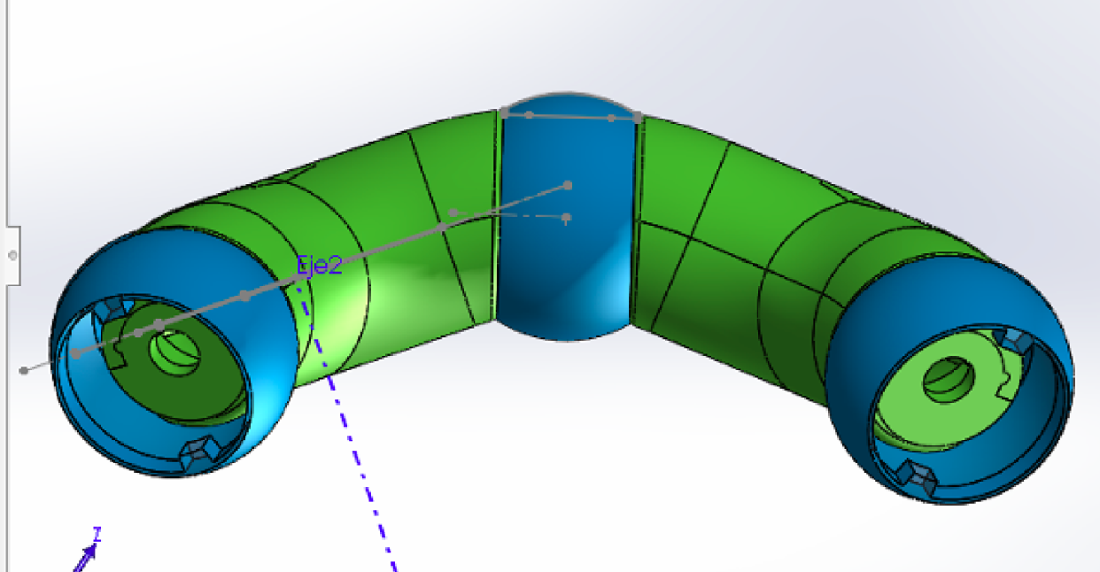
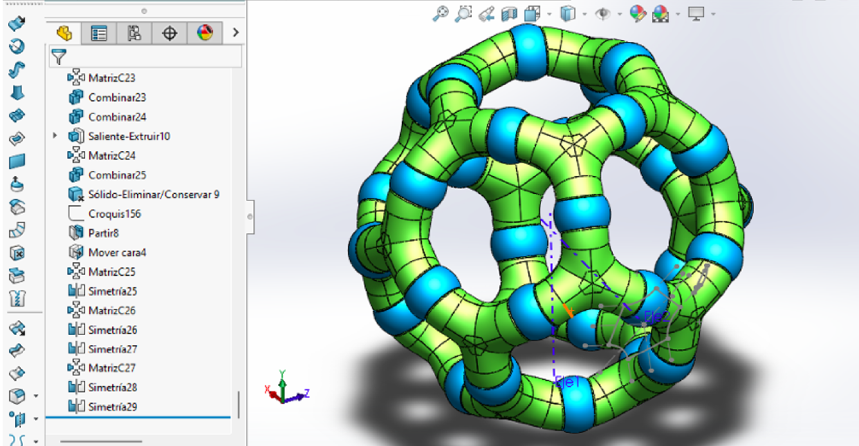
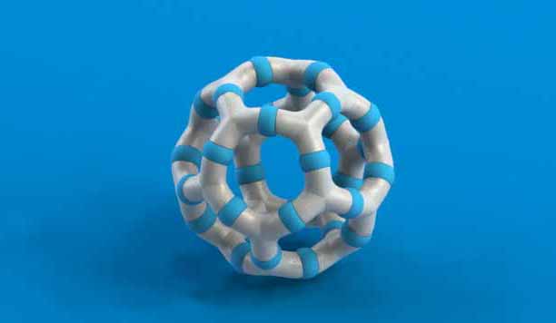
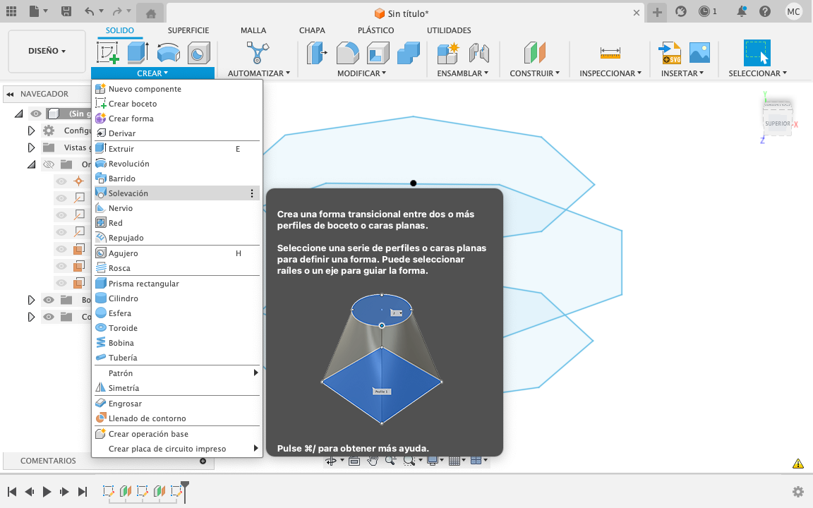
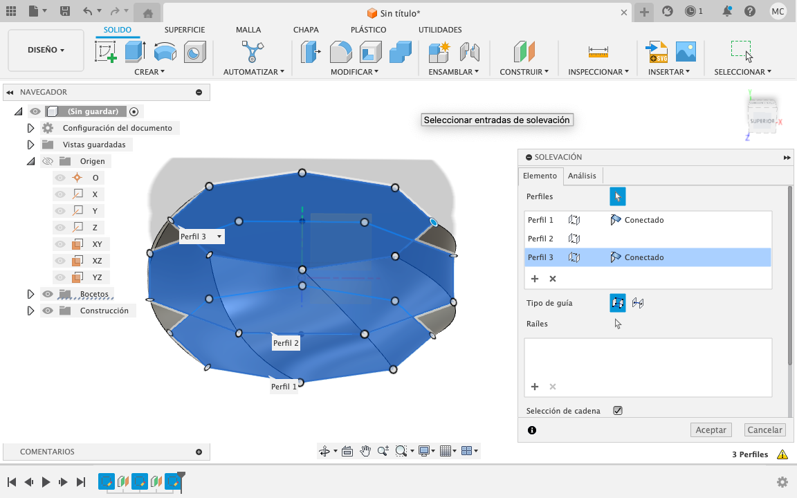
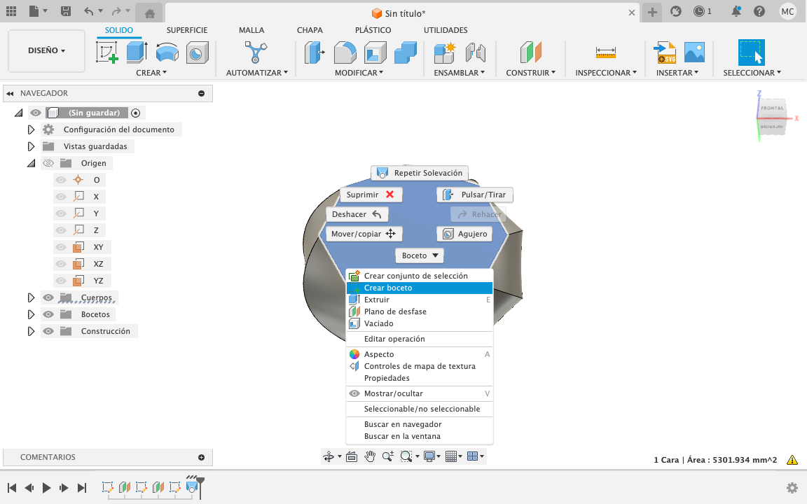
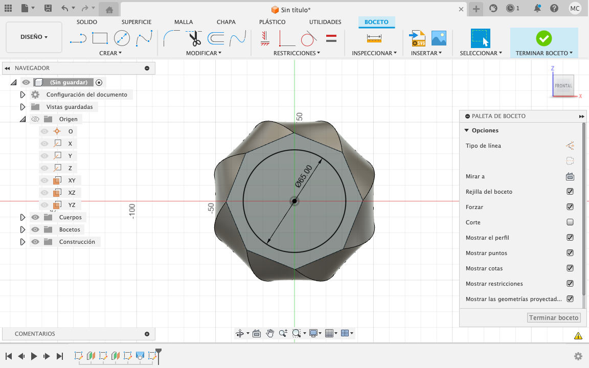
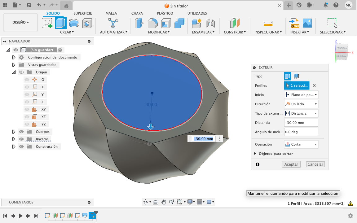
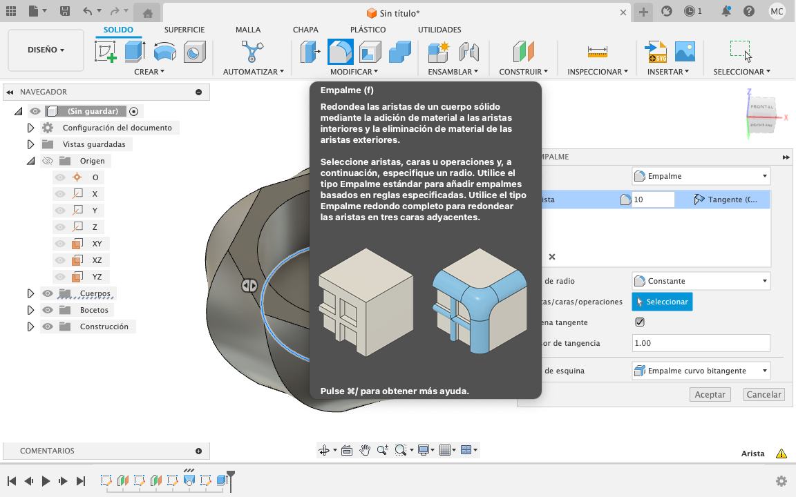
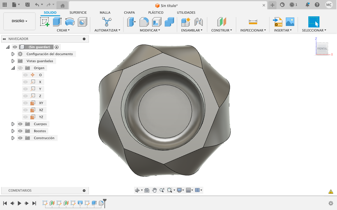
This week I modeled in 3D a possible proposal for my final project, I decided to use Solid Works because it is the program that I commonly use for all my projects, the advantage of this program is his multiple applications such as product design in plastic injection, metal laminated, among others. I personally like the program precision and control of elements. One of the disadvantages is the cost of a montly subscription to this software.

Solid

I started with the polyhedron structure, which is a truncated icosahedron. It is formed by 20 regular hexagons and 12 regular pentagons, and it has 90 edges. The interesting thing about this polyhedron, is the connection system between the hexagons.

To obtain it, I started an sketch from a top plane, drawing one penthagon, then i created a second plane at 142.62° starting on one of the penthagon edges regarding the top plane. And with the “extrude” tool, i created two solids from the sketches.
Then I figure out the center of the truncated icosahedron, creating two perpendicular axes on the center of both sketches that i already have, and putting a point on the intersection. Ending with matrix and mirror tools to verify the closing of the entire truncated icosahedron figure.

Module

I made a new sketch on the face of the hexagon that I had, in order to draw the module that i was interested.

I realized that I needed the faces with the angle of 142.62° to make a face-to-face contact between each module, so I used a hexagonal pyramid that I made with the "recover" tool.
Using the "recover" tool again, I make the module connections, these had to be formed by circles so that can be connected with other modules and used in different positions. Then I repeated this figure using the matrix tool.

To make the body of the module, I draw the guide lines and with the "recover" tool i make the first surface, then the lower one, then i cover these and turn it into a solid, to later join it with the connections that i previously created. And with the ”shell” tool i make this new solid empty, to make it hollow.

UPS!

I realized that I was missing an assembly part to join the connections, then i return one step to make the assembly joints in order to continue with the emptying phase.

With the "split" tool and helping me with a surface, I separate the module in two, upper and lower piece. I also place a guide on the juntion to prevent it from being misaligned when assembling.
I covered the gaps with the extrusion of a circle, above the surface of the joints, and i add a few locks to use them on the upper piece with a boolean subtraction operation. I leave a hole on the center to place the energy conductive material between the modules.
Note: I must keep in mind the safety and amount of energy.

ups again!

I went back again, because I realized that the connections, apart from to being circular, should be symmetrical, so they can be used in various ways.

I only adjusted some errors, but thanks to the solidworks "History", i didn't waste a lot of time redoing the steps I already had.
After this, I just make the connection piece between modules with the assembly system between them, using the "revolve" tool.

Finally

I check the two types of assembly between the modules, one to create the sphere and the other to create a flat structure. I also experiment with a render in solidworks, to preview how would look like.

3D

Downloadable STL files and 3D in SolidWorks.

Render made in Solid Works

Fusion 360

I started using the Fusion 360 program which is a CAD, CAM and CAE software platform for product design and manufacturing, what I liked about this software is its set of tools not only for modeling but also for design of PCB and the machining of parts. You can also use the student version or try the free version for 30 days.

In Fusion 360, there is a step control similar to solid works where you can go back to a specific step or sketch to modify it. To start creating a sketch you must choose a plane and then create a new sketch. In the upper part you will see several tools to start your sketch, for this exercise select the tool "polygon" and modify it to 8 sides with a radius of 50mm.

Then create a second plane with reference to the previous one, now use "construct" tool and select "offset plane", this will have a distance of 20mm.

On this plane you will create a sketch, and draw an octagon with a radius of 40mm.

Then you will create a plane again with reference to the first sketch, and with the same distance of 20mm, but now will be on the opposite direction.

Already having the 3 sketches, we will look for the "loft" tool inside solids section, and we will select the 3 sketches. The construction points must be inserted clockwise.

Now you must create a sketch on top of the solid, and draw a circle with a radius of 65mm.

In solids section, look for the "extrude" tool and select the circle in the properties, the option will be "cut" and the distance will be -30mm.

You have to look for the modify section and select the "fillet" tool with a measurement of 10mm and select the internal edge.

Done, you have modeled a small pot for a mini cactus.

I liked using Fusion 360, it is a very intuitive software, more so if you have already used a similar software and with many tools for different applications.

POT F360 POT STL

2D RASTER

For my 2D design, i rasterize a logo which is a graphic vector that I converted to pixels in case i decide to print it.

Step 1, Start by making a polygon.

Step 2, Use "pen" tool to draw a curved line by points, you can pull these points to create more complex lines.

Step 3, Close the vector with another straight line.

Step 4, Make a matrix with the "rotate" tool that is in the left bar, the angle will be 120° and then click on the copy button, it will only make a element, but to make more press "command" + "D".

Step 5, To finish, use the stroke properties that will be located at the top.

Step 12, To rasterize the image, go to Menu>Object>rasterize and change the values according to your needs. You must remember that you have to save an editable file, because will not be able to edit later, it serves to avoid losing changes.

This week I experimented with a new program, as I had already modeled in SolidWorks, I found it easy to work in Fusion 360, it seemed interesting to me because all of its applications.

Contact me

dimaricruzchavez Linkedin