Input Devices
Week 11 - Documentation
In this week, we are going to go see inputs. Now, the idea is that our electronic circuits receive some action. The following image is a pin diagram of my favlab circuit.
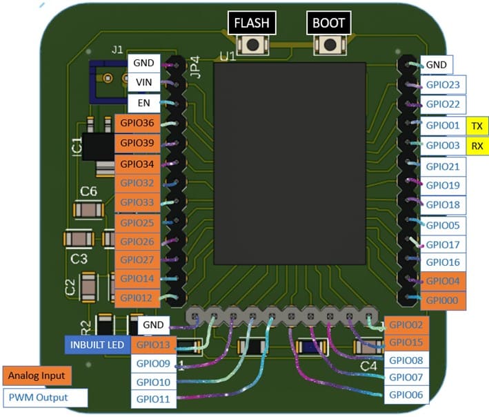
In week 6, electronics design, I reviewed inputs for an esp32 dev board, so we are going to take some of that info to use it here, because it's also relevant.
About electronics desing week
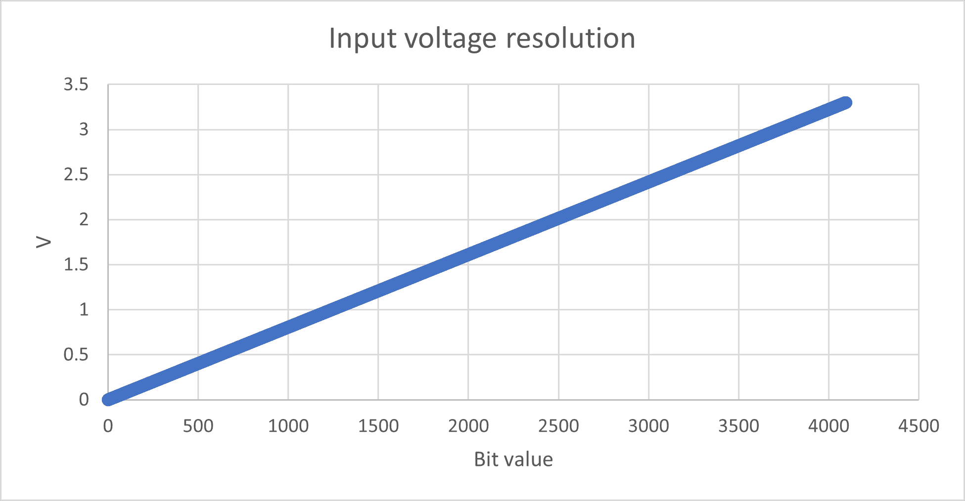
The analog input pins from the esp32 have 12-bit resolution, meaning that the range varies from 0 to 4095, having 0 for 0V and 4095 for 3.3V. In other words, the resolution of every bit is of 0.000806V! In the next graph, you can see the linear behavior for the input resolution.
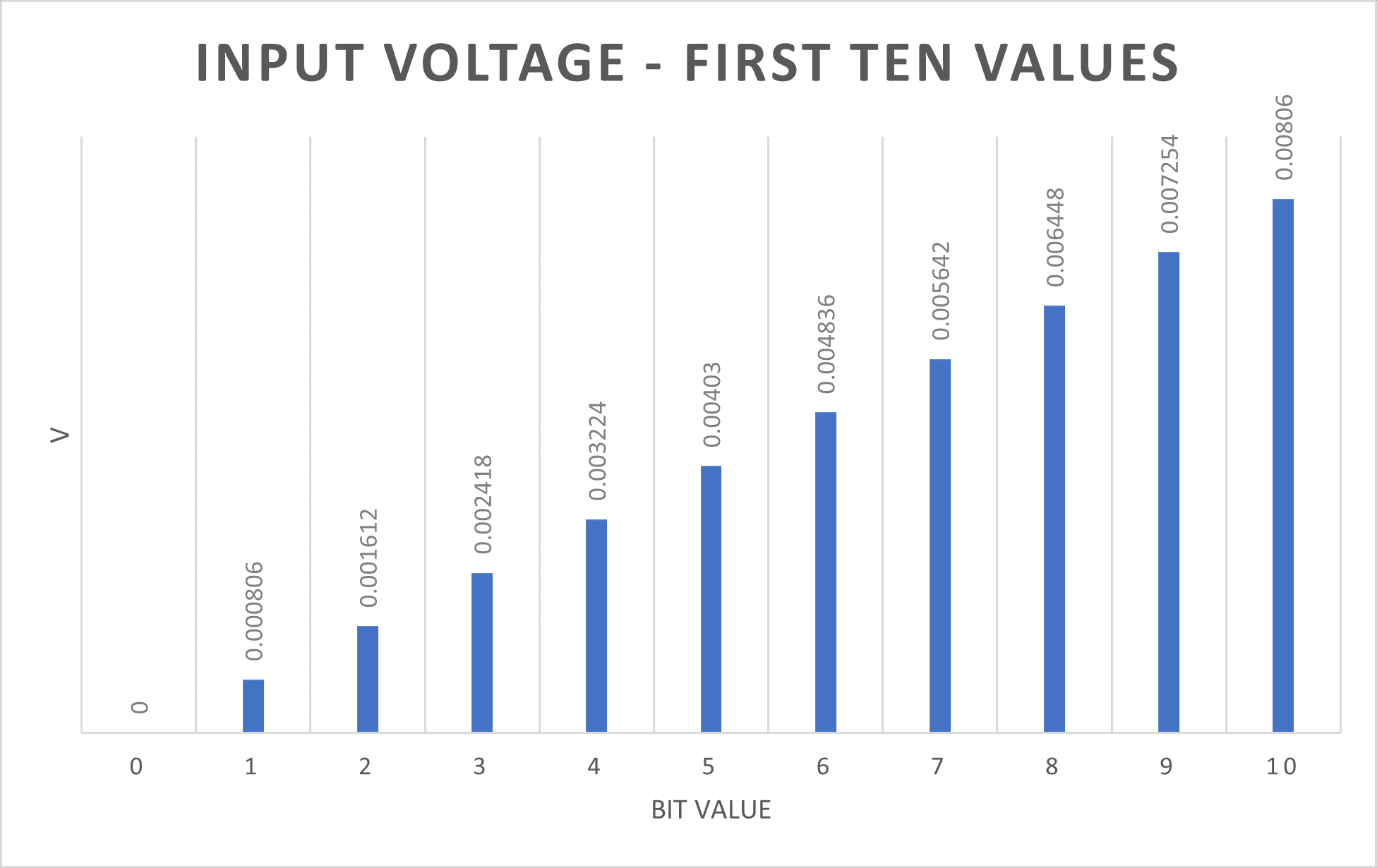
If you zoom in, just to observe the first ten values, you can understand how small the voltage difference is.
Inputs in my circuit
For my individual assignment, I'm using a flex sensor. These sensors change their resistance as you bend it, working like a potentiometer, except that its body substitutes the knob.
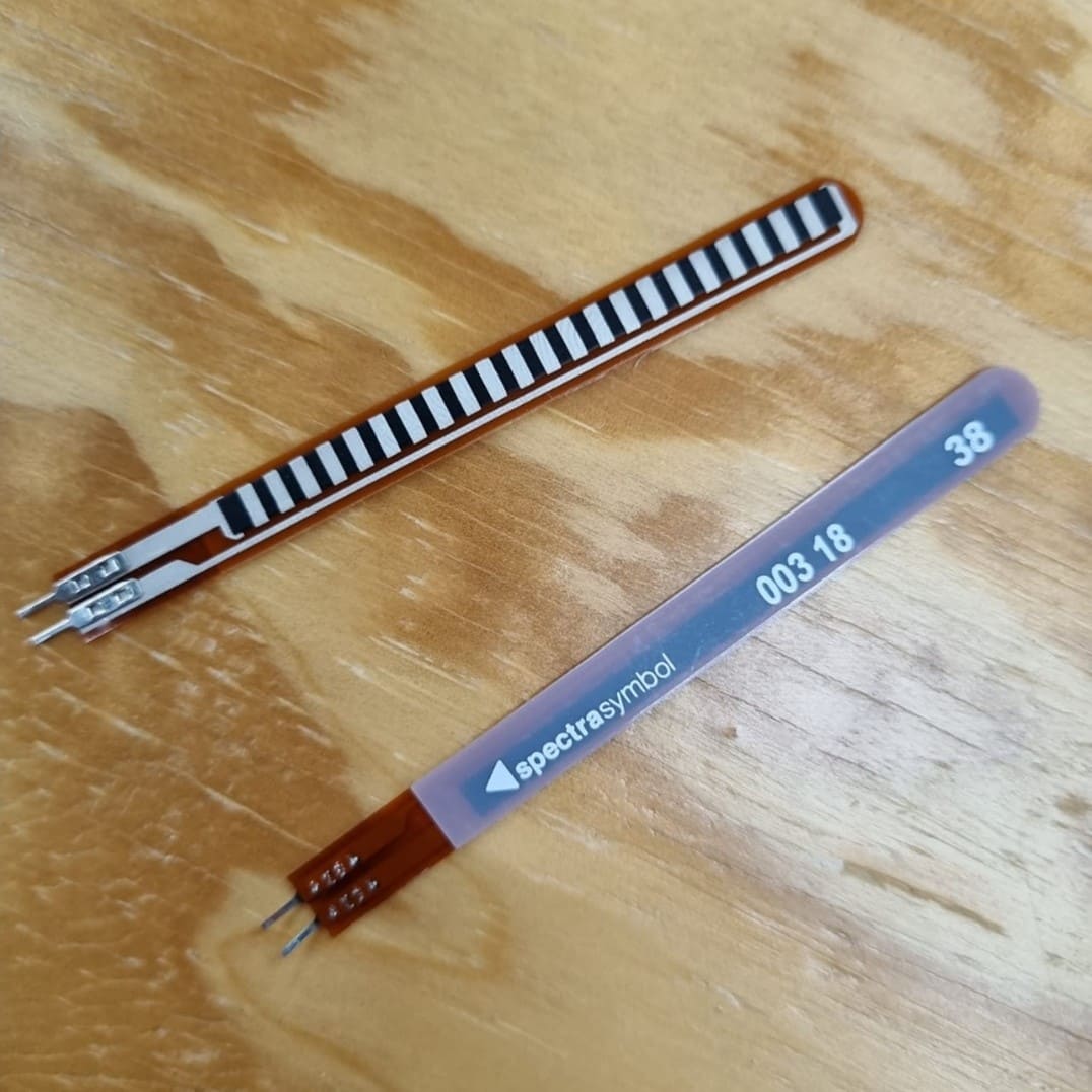
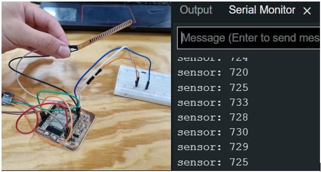
My project consists of measuring the value difference while bending the flex sensor. Measuring the sensor without being bend, I got values around 720. Remember that the sensor is an input, so the value can go from 0 to 4095 and while the sensor is actually changing the resistance, the value that gets in the circuit is the voltage difference.
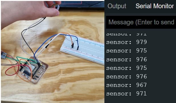
Bending the flex sensor, as seen in the image below, got a value around 975.
Now, that we know these values, we can create a finger activation device, where I can turn on and off a led with the movement of my finger!
*With Protoboard*
*With the inbuilt led*
The group assignment is to probe an input device's analog levels and digital signals, so I connected the circuit to an oscilloscope. In the next video, you can observe how the voltage varies as I bend the flex sensor.
Flex sensor program
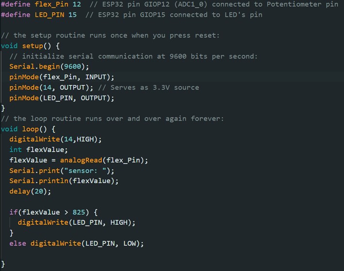
The program for my circuit consists of an input, the flex sensor, and two outputs, one for the led and another one that serves as a voltage source. The setup() initialize serial communication and sets the pins for inputs and outputs. The loop() set the routine that will run over and over, where I´m reading the value given by the flex sensor, and then deciding if it passes the bend umbral so it can turn on the led. I used 825 as an intermediate value given the previous results.
Here, you can download the program: