Output Devices
Week 9 - Documentation
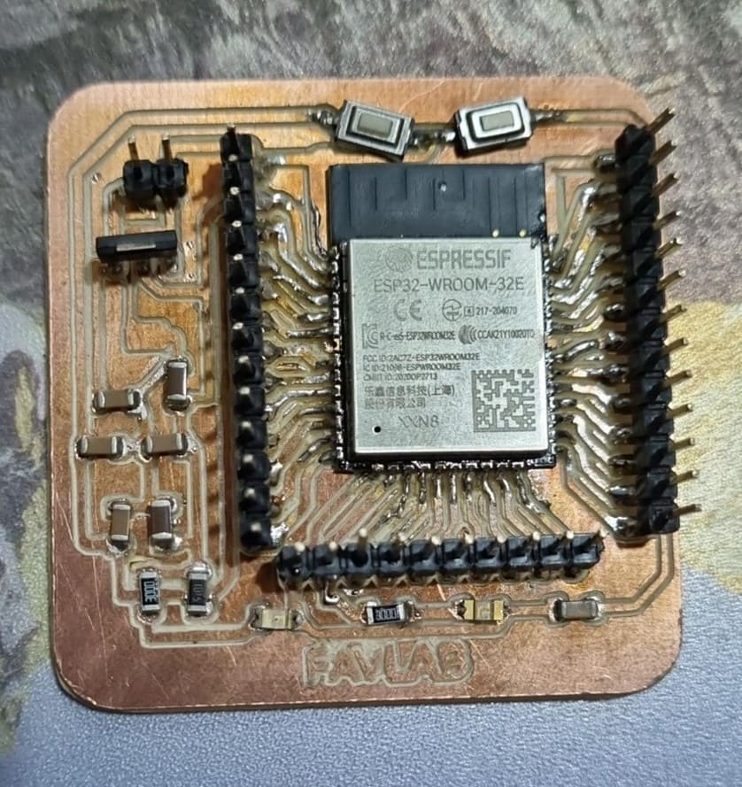
In this week, we are going to see outputs. The idea is to give it some action to our electronic circuits we did last week. Our microcontroller unit is an esp wroom 32, and the circuit has a couple of leds, buttons and pins for the GPIOs.
In week 6, electronics design I reviewed outputs for an esp32 dev board, so we are going to take some of that info to use it here, because it's also relevant for this one.
About electronics desing week
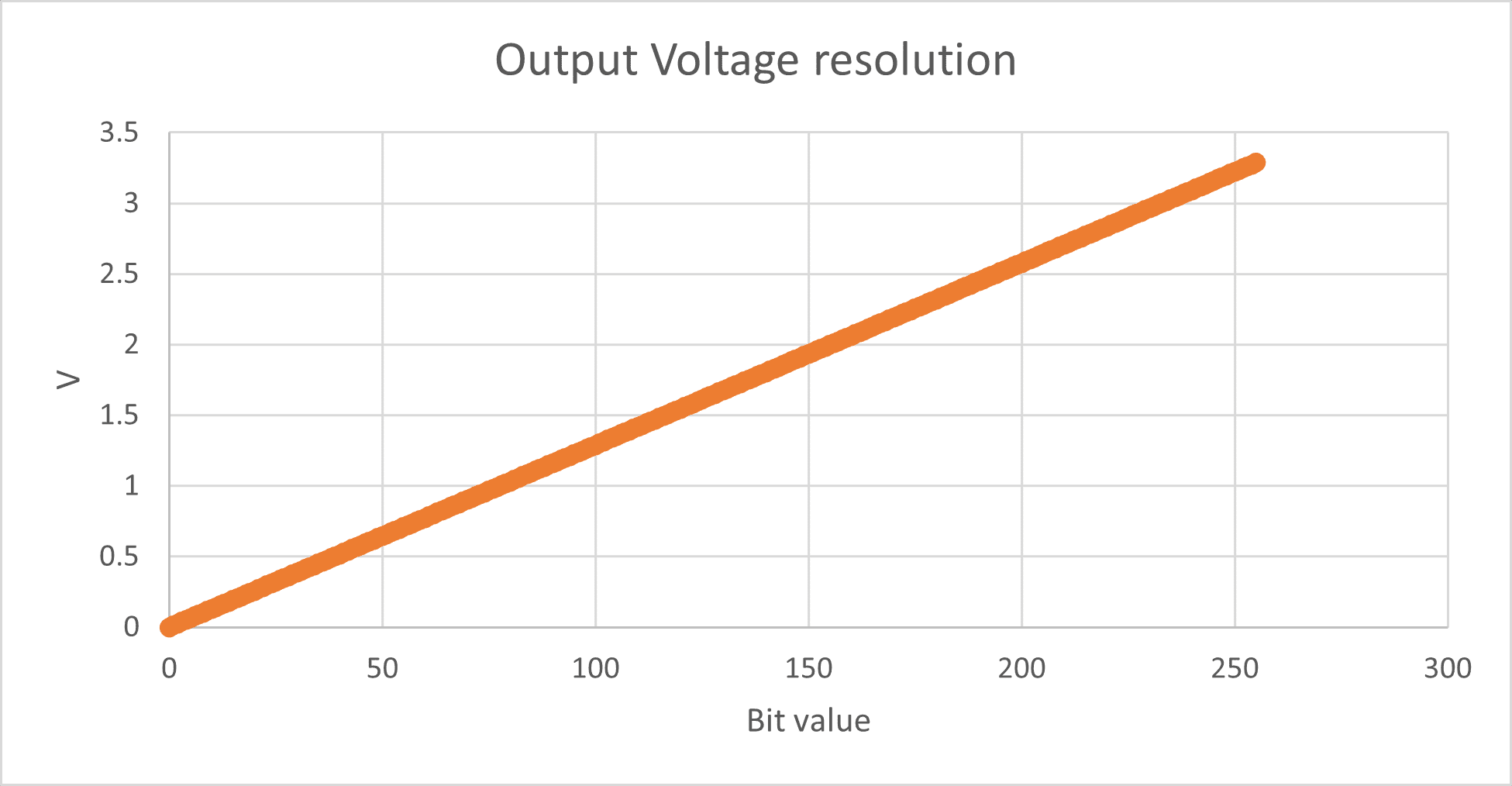
The analog output pins from the esp32 only have 8-bit resolution, meaning that the range varies from 0 to 255, having 0 for 0V and 255 for 3.3V. In other words, the resolution of every bit is of 0.01289V. In the next graph, you can see the linear behavior for the output resolution.
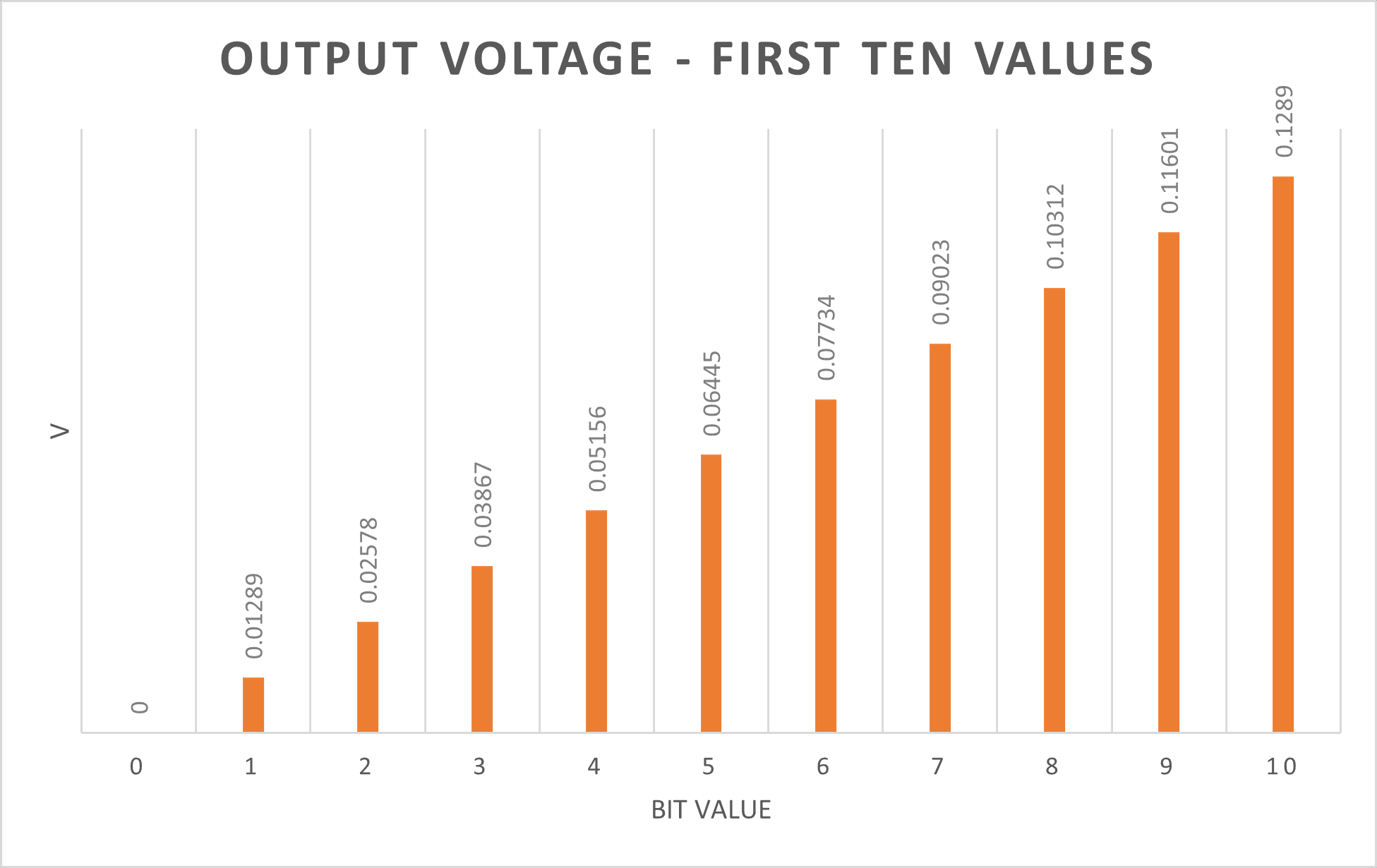
If you zoom in, just to observe the first ten values, you can see the voltage difference between each value.
"Analog Output" - PWM Signals
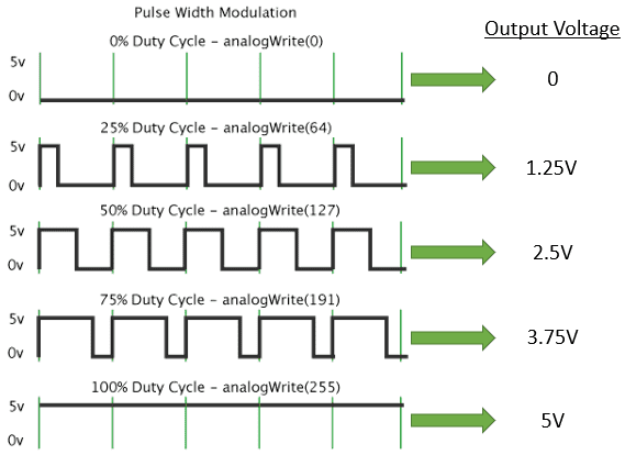
PWM stands for pulse with modulation, and it is used to obtain analog results by modulating digitals signals. Microcontrollers are digital devices, and as far as I know, none of them all can operate with pure analog outputs. Digital signals are those of On and Off, True and False, 1 and O… Basically, it operates in two states, meaning it is a discrete signal. In contrary, analog signals can vary in between two extreme points, having a continuous behavior.
The next image is a representation of the difference between the analog and digital signals.
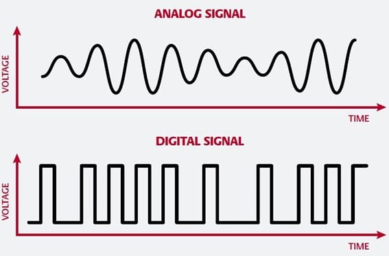
Image taken from Digital Audio Cables
The microcontroller modulates the pulse width of the digital signals, hence the name PWM, to mimic the analog characteristic of having a state between two values. An on-off pattern, square wave, is used, where the moment the signal is “on” is called pulse width. By modulating the pulse width in each period results into an in-between value from the on-off scale, allowing us to have “analogic” signal.
The next image is a representation of how the PWM works in microcontrollers:
The image was modified from the original one taken from: Basics of PWM (Pulse Width Modulation)
Now that we know what PWM signal are and how we can use is to give us analog outputs in our microcontrollers, let's test it.
Ouputs in my circuit
Ok, we are going to run the same programs for the faded led (week 6) and controlled servos (final project - first prototype), but with my own circuit.
In the first task we are fading a built-in led using a potentiometer as an input value.
The second task will consist of controlling a servo motor using the same potentiometer as before.
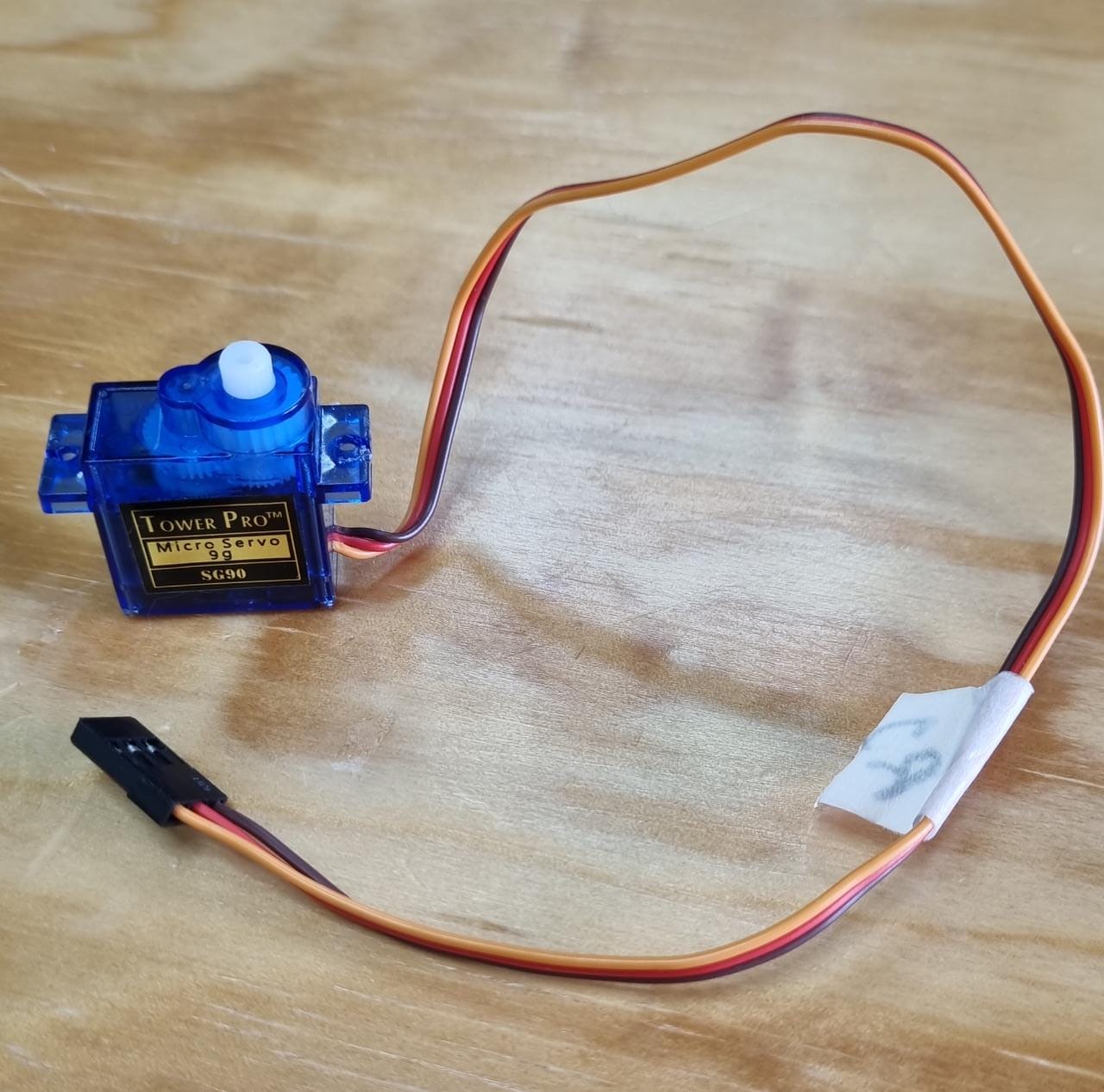
The servomotor I'm using is a SG-90, and you can find it here.
TowerPro SG-90 Features:
• Operating Voltage is +5V typically.
• Torque: 2.5kg/cm
• Operating speed is 0.1s/60°
• Gear Type: Plastic
• Rotation: 0°-180°
• Weight of motor: 9gm
• Package includes gear horns and screws.
Servo Control:
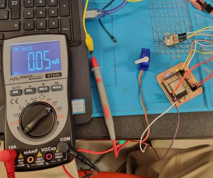
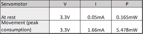
Now, we are going to connect a multimeter in series with my servomotor to find how much current it draws while it is being operated.
In rest position the current was around 0.05mA.
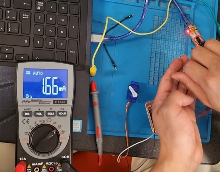
When I was moving the potentiometer, meaning that the servo had to change its position, the servo draw more current, having peaks up to 1.66mA.
Following the Power equation, P=VI, we can obtain how much power the servo consumes:
In the next video, we can observe the pwm signal of the circuit to control the servmotor.
Here, you can download the programs: