Computer controlled cutting
Week 3 - Documentation
Laser cutter parametrization
- Laser cutter machine: Corvus SF960I
- Software: RDWorksV8.01.54
- Material: Plywood 1/8"
First trial
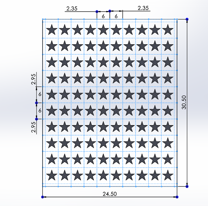
Step 1: I did a 10x10 matrix with stars in Solidworks, units of the drawing are in cm.
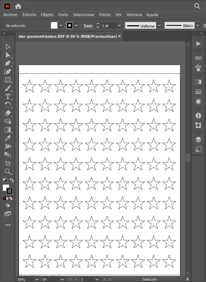
Step 2: Save the document as .dxf file, or any other that the laser cutter software can open.
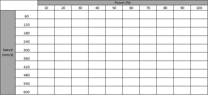
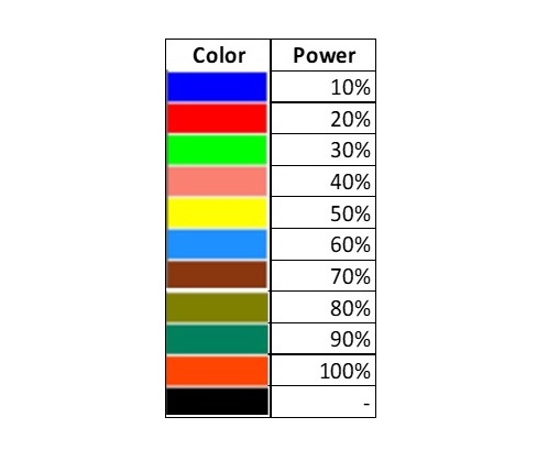
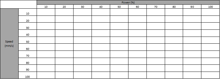
Step 3: Create a table to use it as reference to change the laser parameters. The power is set up in percentages and the speed goes up to 600mm/s.
Step 4: Open RDWorks.
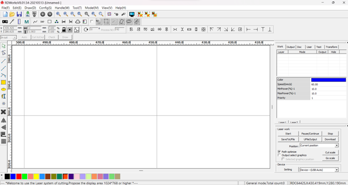
Step 5: Open the file you want to work with.
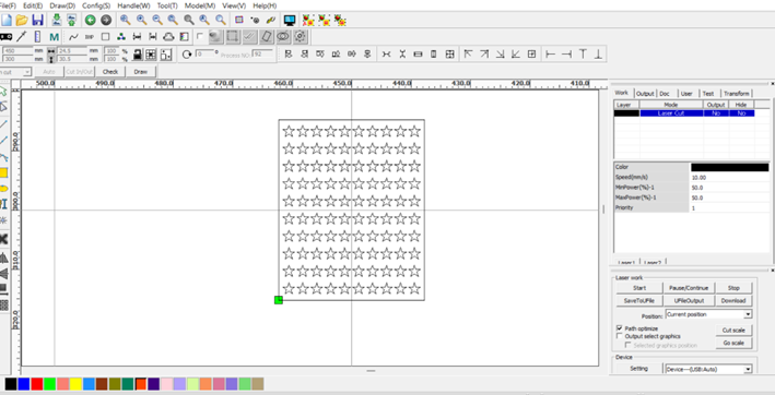
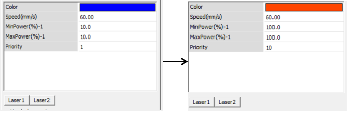
Step 6: Give a different color to the stars in the first row so that each one can have different parameters.
Step 7: Give each color different parameters following the table shown before. As we are working through the rows keep the speed the same for each color until go forward to the next row. The power is going to vary for each color.
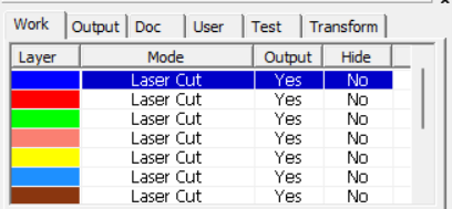
Step 8: Make sure that the Mode is in Laser Cut, if not double click on it so you can change it. As well, the Output option needs to be Yes for each color, except for the black one, which needs to be No, so that it makes nothing with the rest of the uncolored stars. Leave Hide as No.
Step 9: For each color set the same speed, until we progress with the rows, and set MinPower and MaxPower going from 10 to 100. Every time you make a change press Laser 1 to save it, you will now it has been saved when the decimal point appears.
Step 10: Connect the computer to the machine and start the process.
Step 11: This is the first row.
Step 12: Repeat from step 6 to 11 changing the velocity in each row.
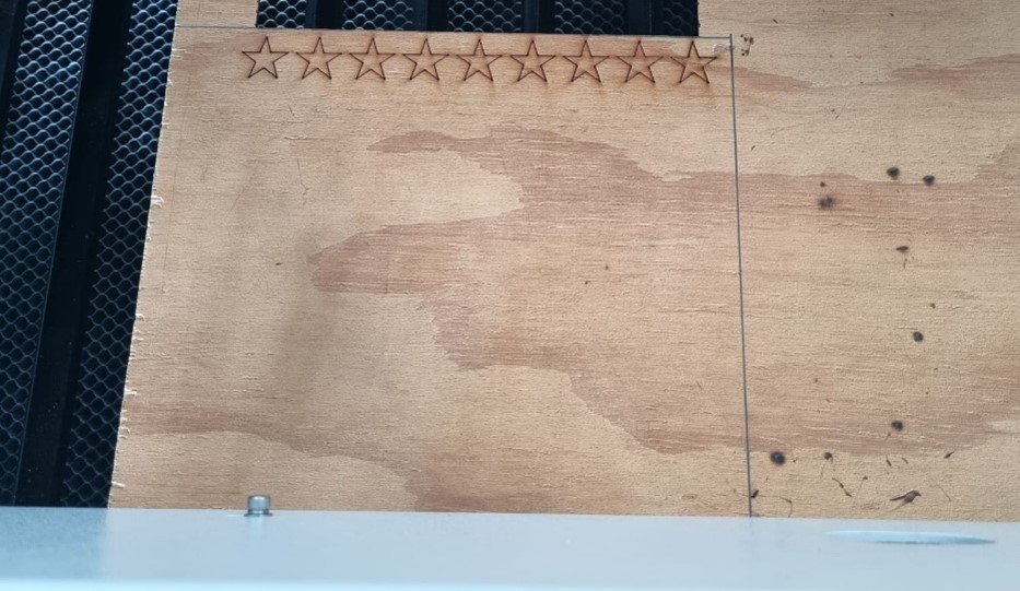
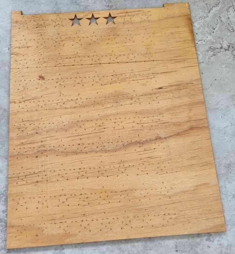
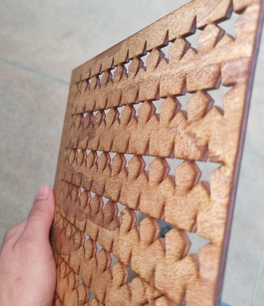
The results of the first trial showed me that that the set of parameters chosen weren´t right for cutting the plywood. The laser moved too fast, not giving it time to penetrate the board as you can see in the next image. Only the first row could cut some of the stars through. Even though the power increases going right seen from the front part (going left from the shown image) it doesn´t cut the stars. This could be because that amount of power is actually burning the material instead of cutting it.
Second trial
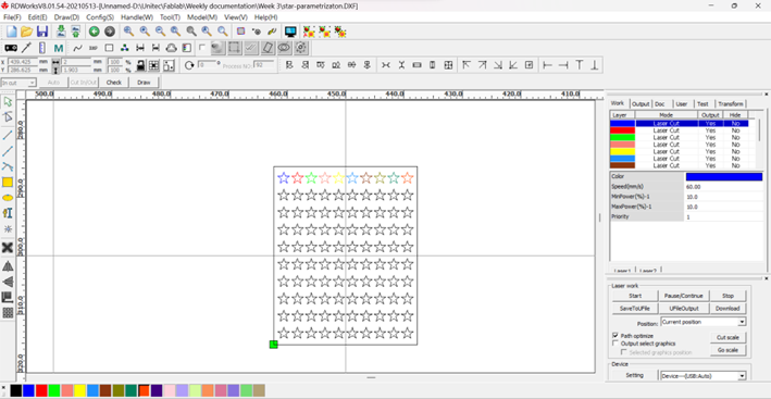
Step 1: I used a new set configuration going from 10 to 100mm/s with the same power configuration from 10 to 100%.
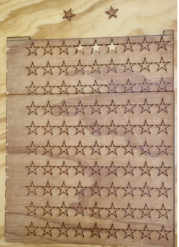
Step 2: I repeated the same process from the first trial with the new configuration. The image shows the front side (left) and back side (right).
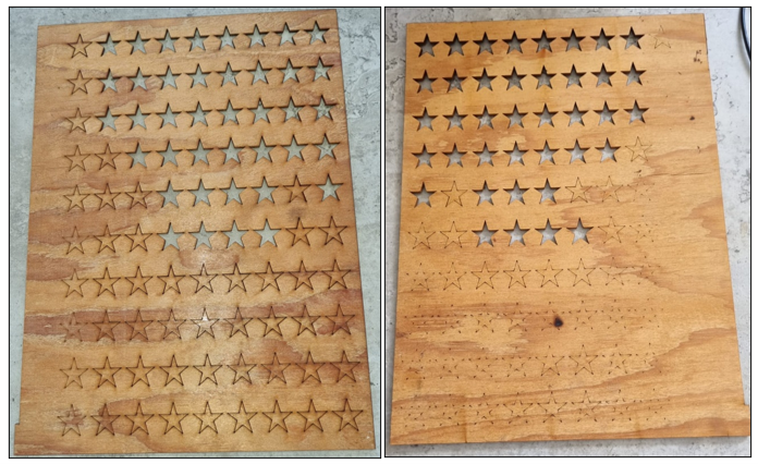
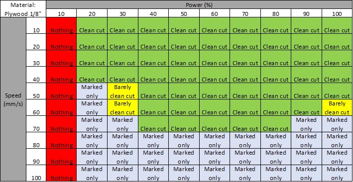
The second trial shows the best parameters to use for cutting plywood 1/8” with the laser. The laser was able to cut stars from the 10 up to 70mm/s.
The difference between the cuts can be noticed when you inspect the side of the stars or the table. As seen in the picture, the cuts where the laser moved more slowly left a darker shadow in the sides than those where the laser moved faster. This becomes an aspect of the finish and aesthetics you want.
Kerf
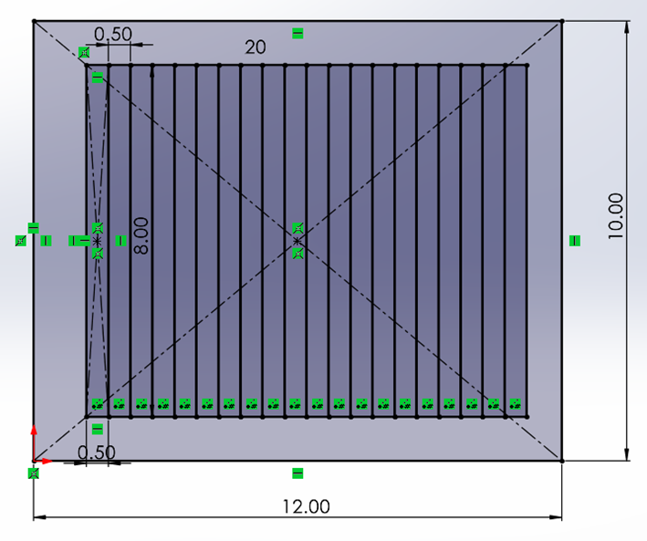
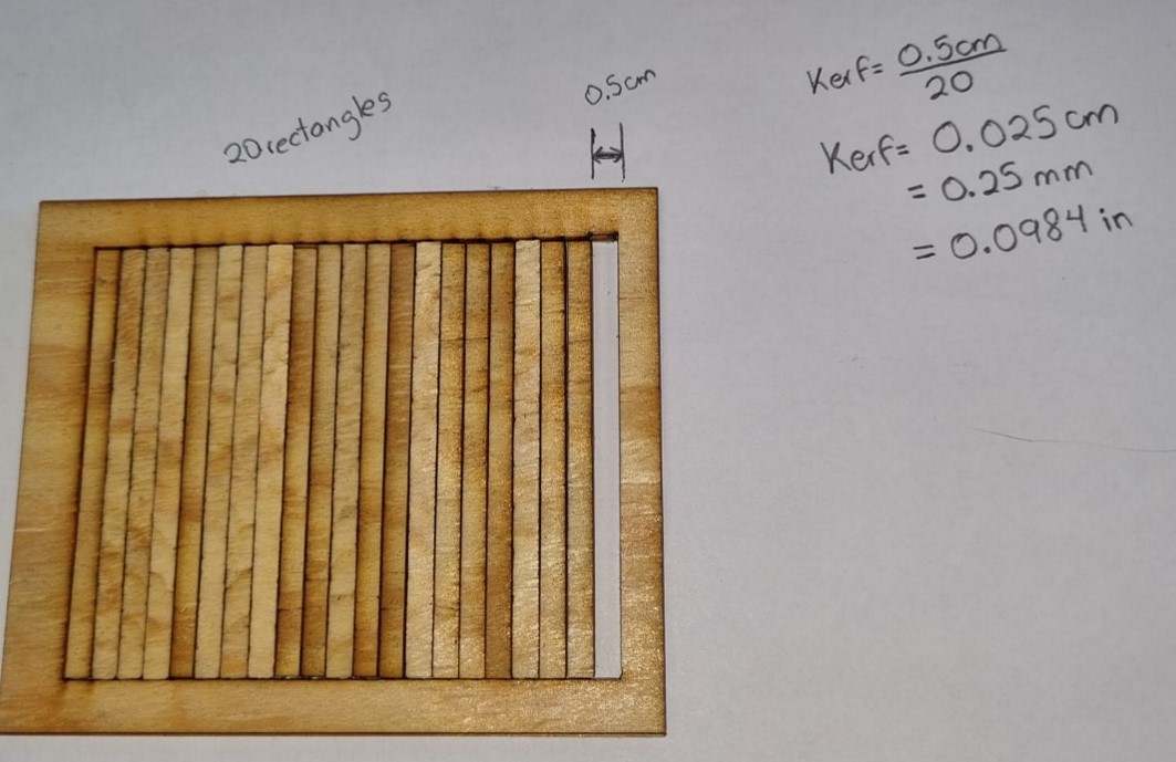
To measure the kerf of the laser cutter I drew a rectangle of 12x10cm with 20 inner rectangles of 0.5x9cm. The image shows the dimensions in cm.
I cut the rectangles with the laser machine.
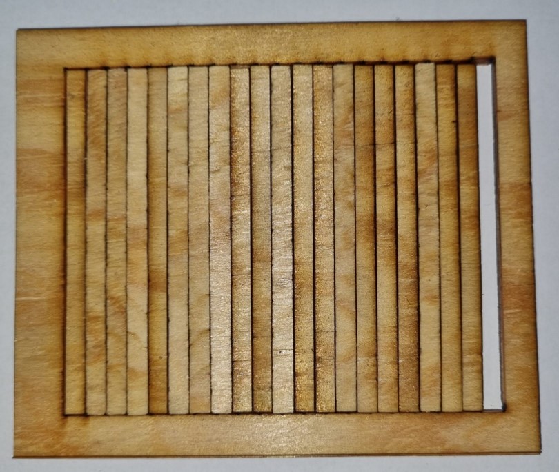
I measured the gap left by the cut of the rectangles with vernier caliper.
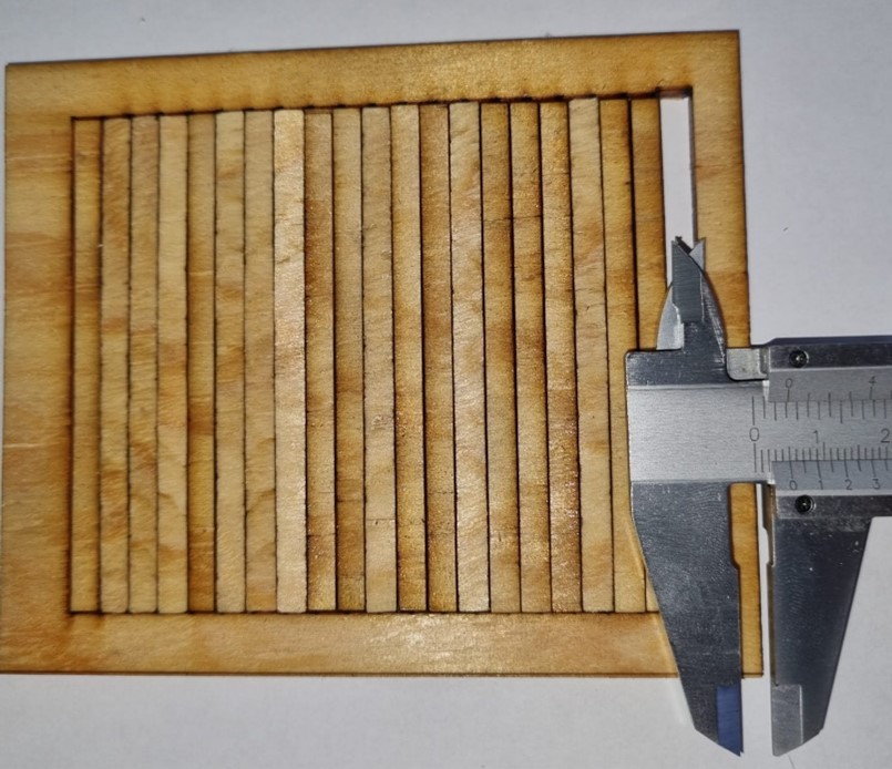
The gap is of 0.5cm
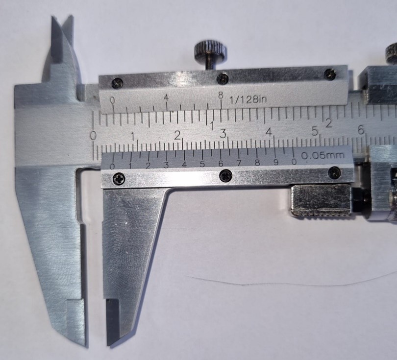
With a 0.5cm gap cutting 20 rectangles I calculated the kerf, getting 0.025cm.
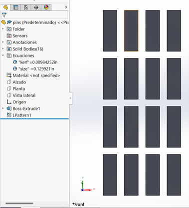
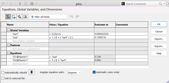
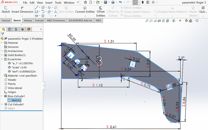
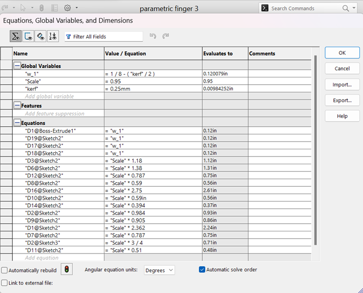
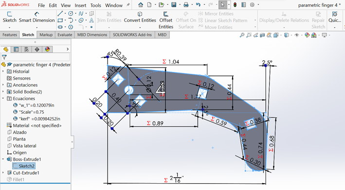
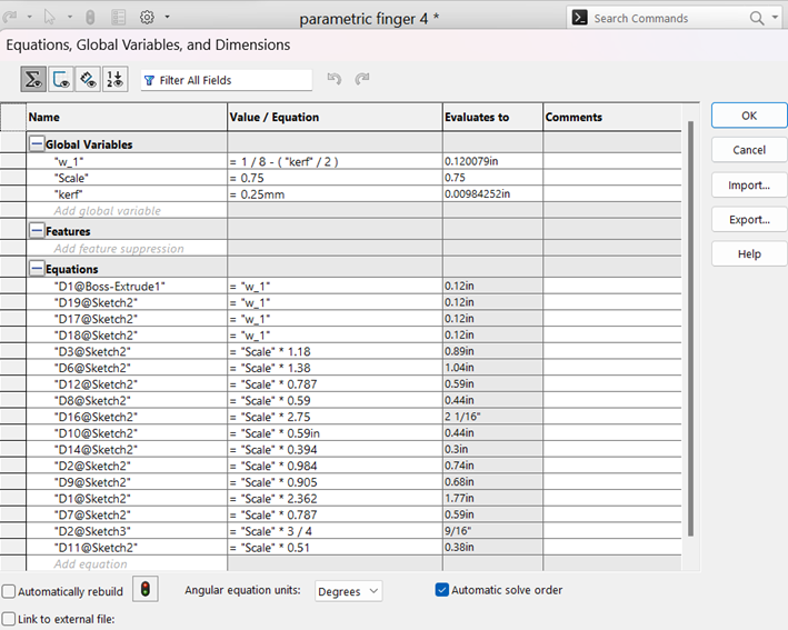
Parametric construction kit
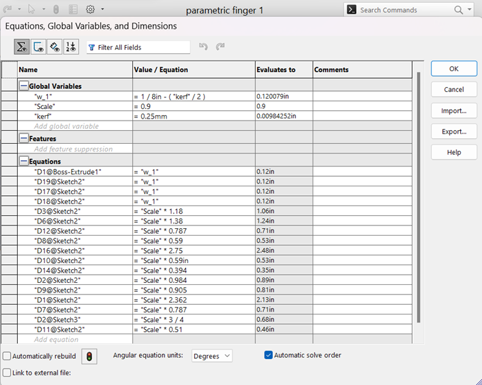
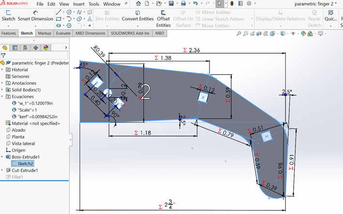
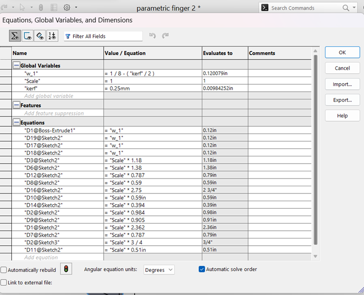
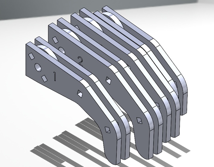
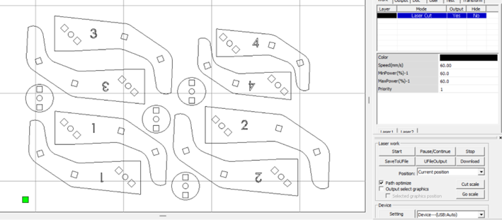
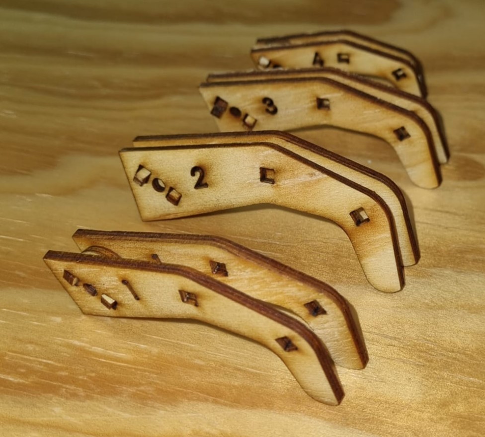
The following set of images account for the design and construction of the fingers of the pianonator. The design was done including the kerf made from the laser. As well, the fingers were designed using formulas, so you can scale the size of each finger, to make it look more like my own fingers!
Pins
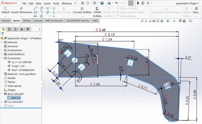
Parametric Finger 1
Parametric Finger 2
Parametric Finger 3
Parametric Finger 4
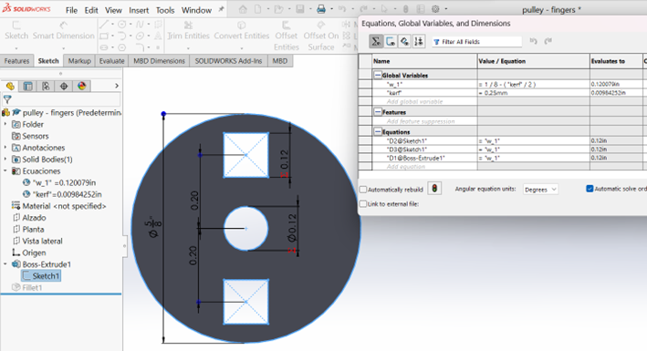
Pulleys
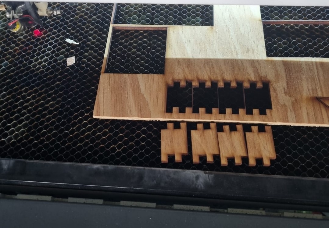
Cutting the elements
Fit Press Kit - Box
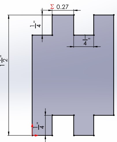
Sketch of box side without considering kerf.
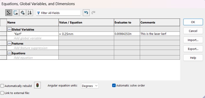
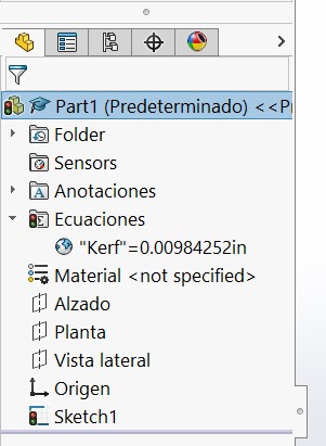
To consider the kerf, we need to use parameters. So, I go to Tools > Equations to add it.
Now, we have can use the parameter in our dimensions.
Then we add a dimension where we want to consider the kerf as part of it. We multiple the kerf by two considering the laser cut will be removing from two sides.
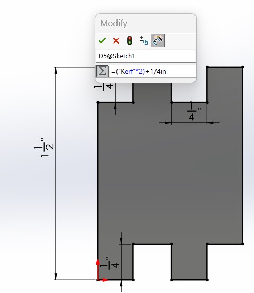
You will then notice that the dimension considering the parameter has a sigma sign. In this case, I'm adding the kerf parameter to the protruding fingers, to allow for a better press fir considering the dimension reduction from the laser cut.
Then we cut the parts to form a box.
Results:
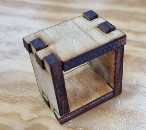
As you can see in the following video, the press fit kit assembly of a box is working appropriately.
Group Assignment
We divided some types of joints so we could try them all and we could share our results:
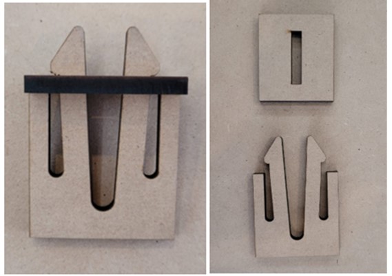
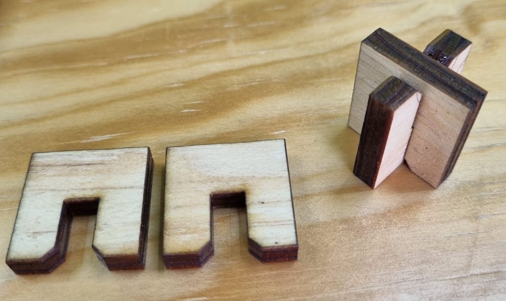
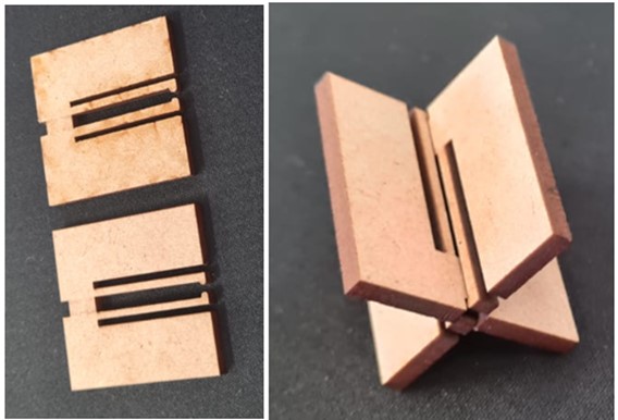

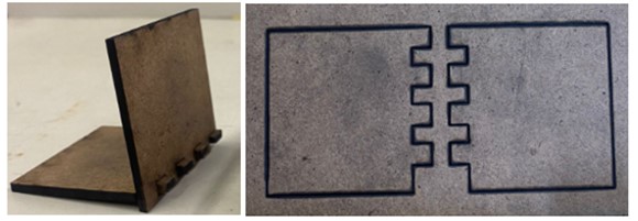
You can download the .dxf with the joints here:
Vinyl Cutter
- Vinyl cutter machine: EXPERTII LX
- Software: Illustrator
- Material: Adhesive vinyl
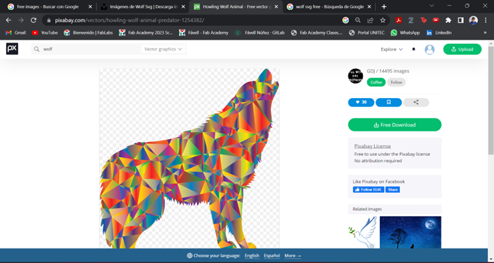
I searched for a free image in the web.
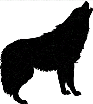
I downloaded it, but I only want to use only the outline, so I used Paint to paint the inside colors. Then I converted the image to svg.
Then, I opened Illustrator.
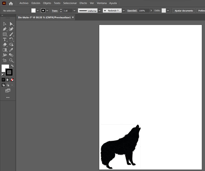
Pasted the image to cut.
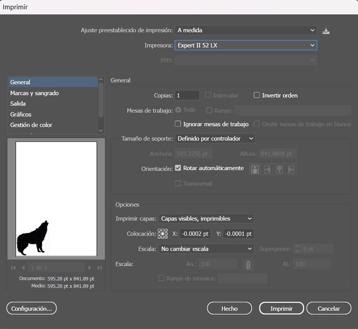
Selected the print option.
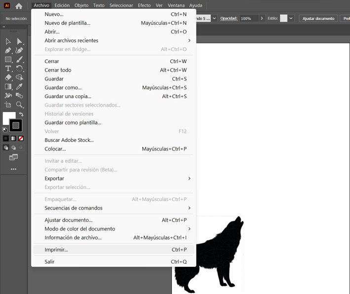
Make sure to select the plotter and then send it to print.
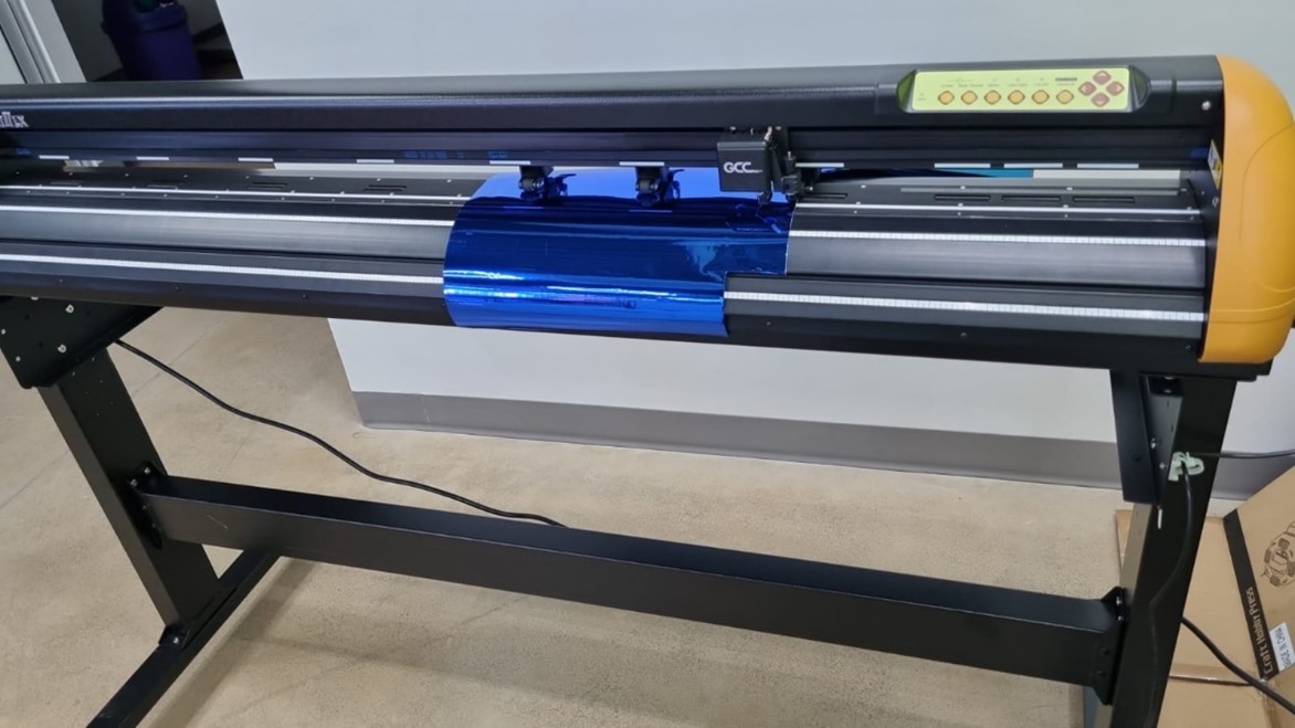
Then, the vinyl cutter starts the process.
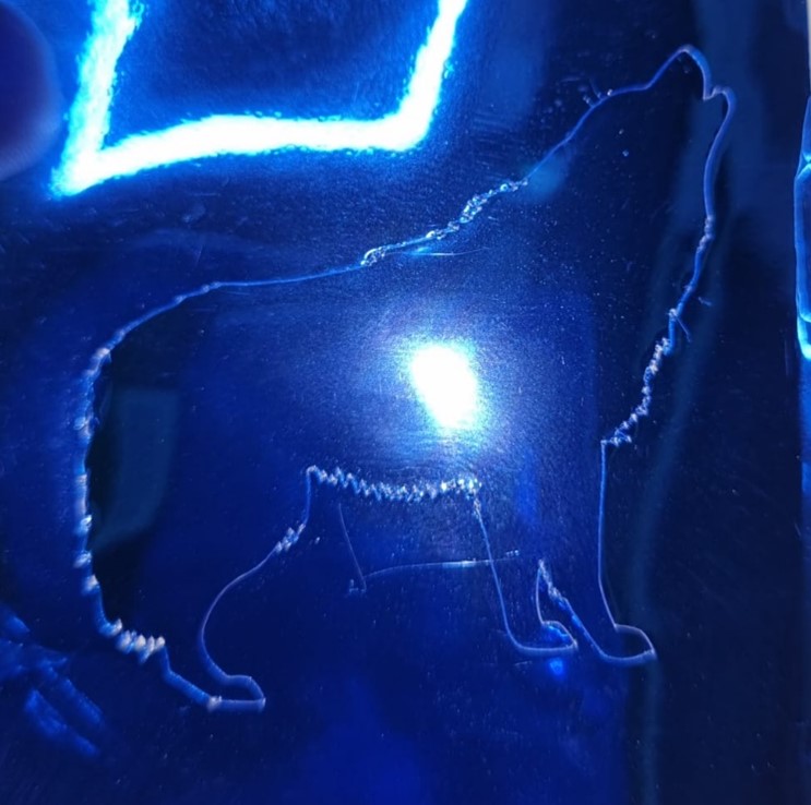
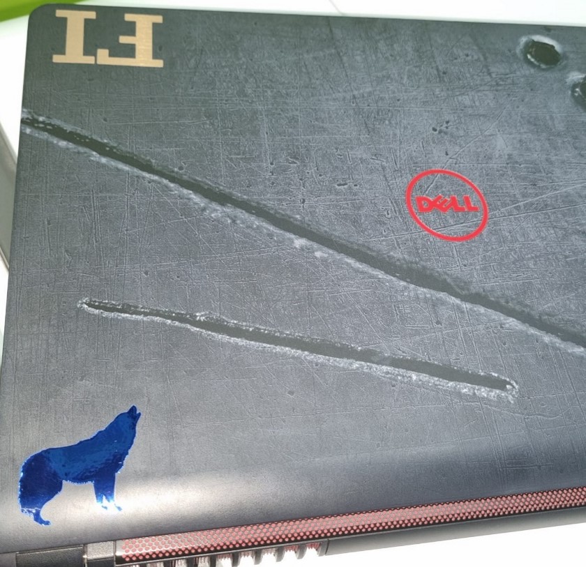
Wolf Sticker:
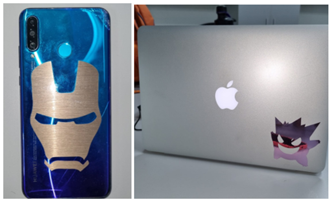
Other stickers made:
You can download the parts here: