Computer Aided Design
First Design
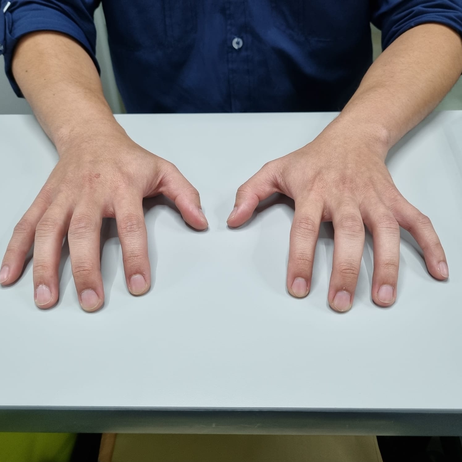
The pianonator will consist of a pair of robotic hands with 10 servo-controlled fingers. The robot hands
will be a model of a human hand. They will move along the keybord through a rail controlled by a stepper motor.
Week 2 - Documentation
Let's go step by step the process I followed to create the first 3D model of my Pianonator. I’m doing my models in Solidworks, but you can choose your software of preference for the design. The initial step to always do is check if you are working in the right units, trust me, things can go wrong if you can´t handle your units, if not ask Sheldon Cooper…
And then go full Picasso…
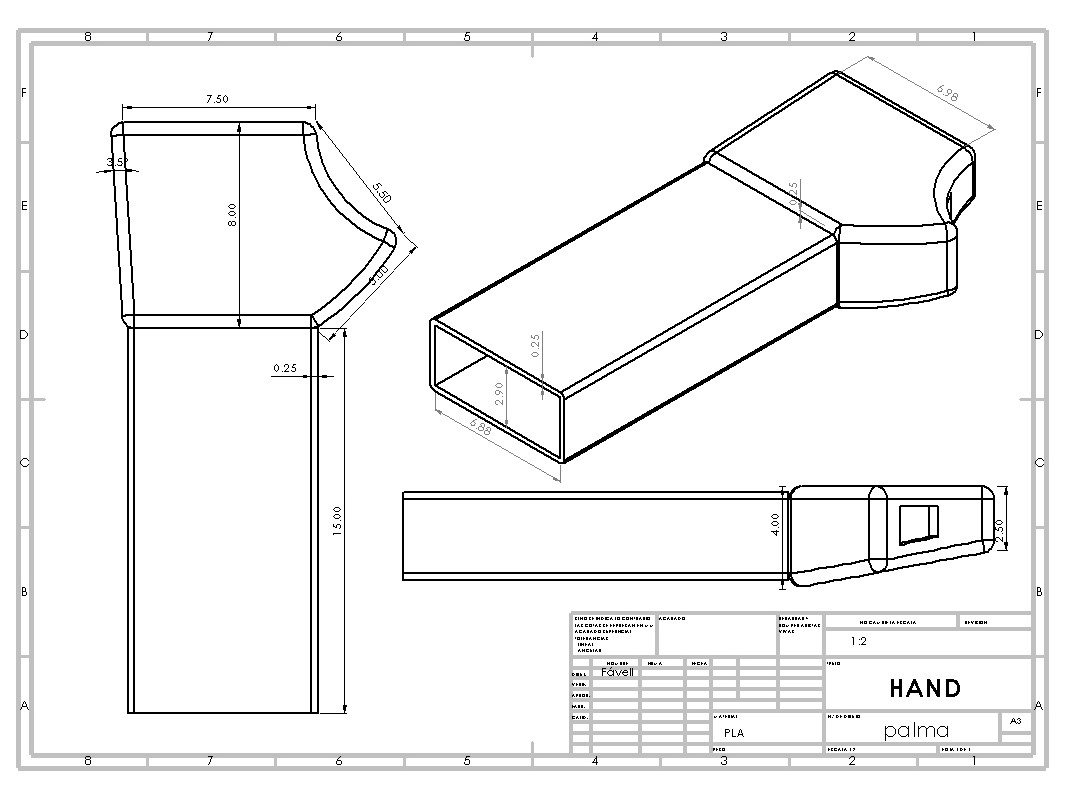
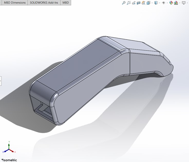
Hand's Model
1 / 17
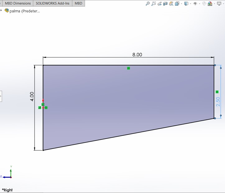
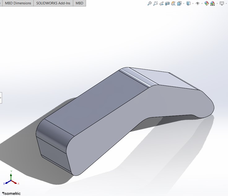
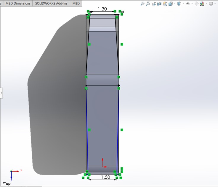
Step 1: Open a sketch in the right plane and draw a trapezoid as seen in the image.
2 / 17
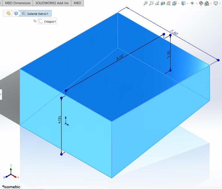
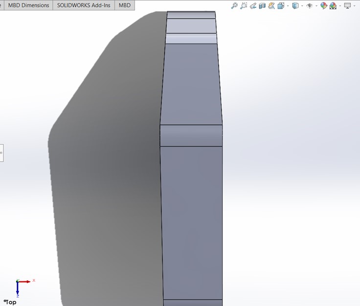
Step 2: Make an extruded base in the middle plane.
3 / 17
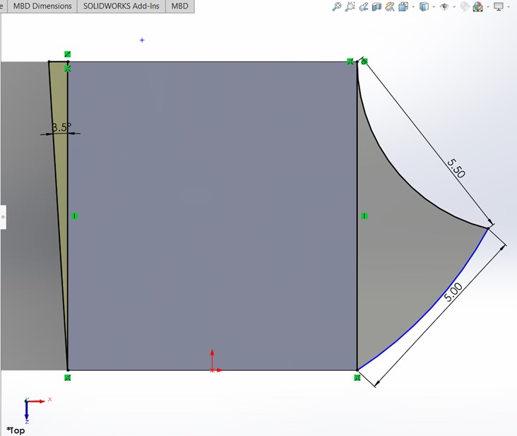
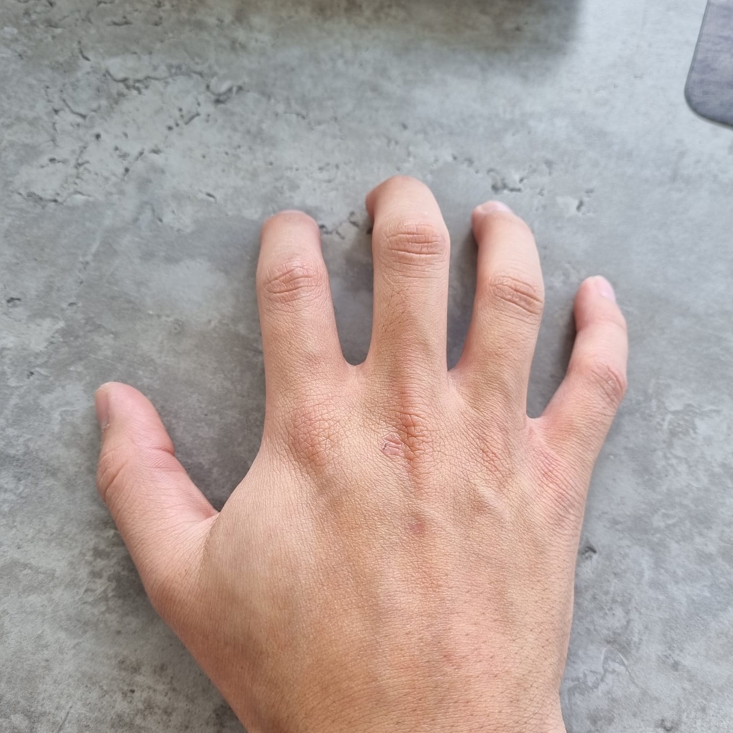
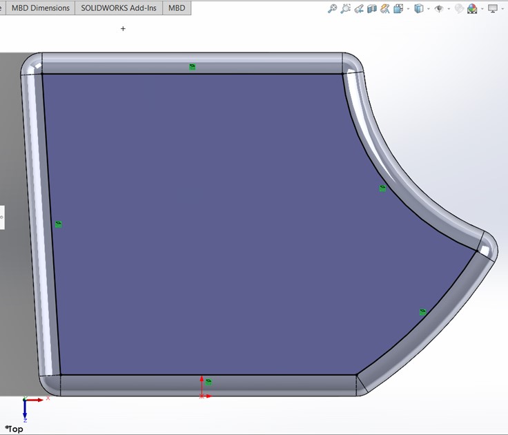
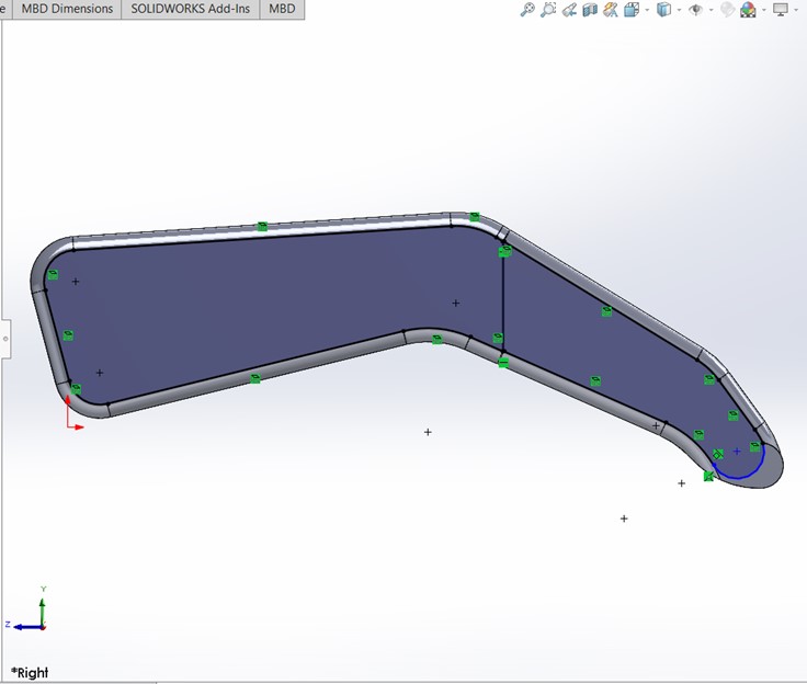
Step 3: Open a sketch in the top plane and draw the outline of the hand as seen in the picture.
4 / 17
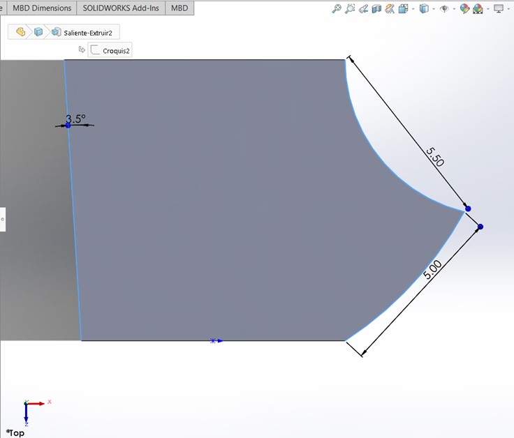
Step 4: Extrude the contours to match the solids made in step 2.
5 / 17
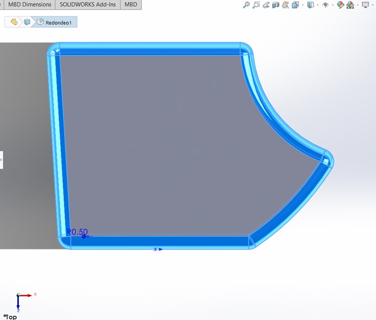
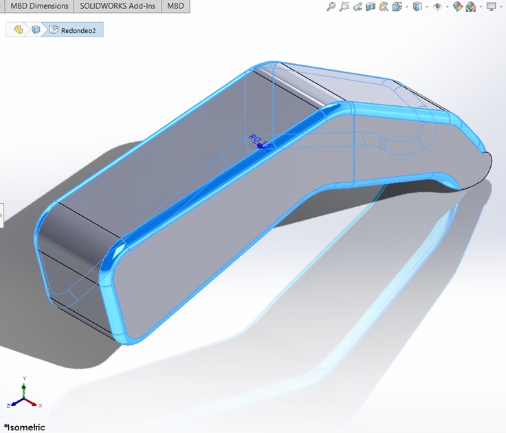
Step 5: Do a fillet to all the corners of the solid to make it smoother.
6 / 17
Step 6: Make another sketch in the top plane and use the Convert Entities operation with the internal outline of the hand.
7 / 17
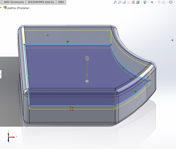
Step 7: Make an extruded cut that go 1.60cm up and 0.40cm down.
8 / 17
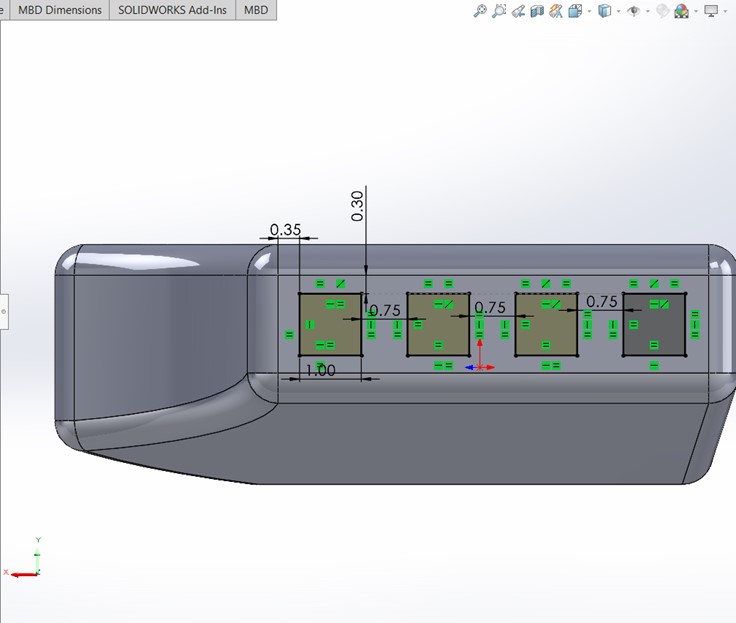
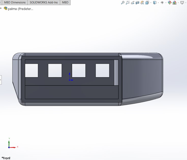
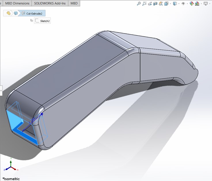
Step 8: In the front part of the hand, where the fingers should go, make a sketch and draw four squares as seen in the picture.
9 / 17
Step 9: Extrude a cut enough to make the holes.
10 / 17

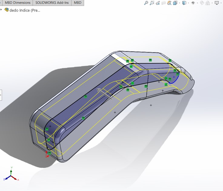
Step 10: Make a plane using the front and right plane as reference to make a diagonal one. Then create another plane parallel to this one with a 7.5cm offset.
11 / 17
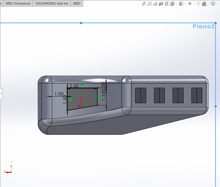
Step 11: Draw a trapezoid in the previously made plane.
12 / 17
Step 12: Step 9: Extrude a cut enough to make the hole.
13 / 17
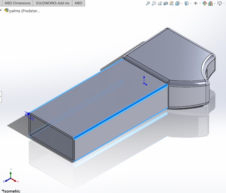
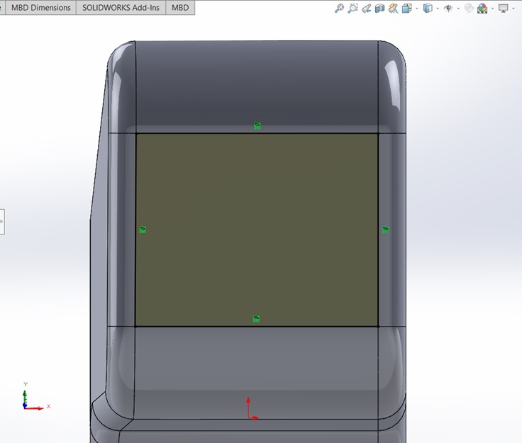
Step 13: Go to the front view and select the rectangular face and open a sketch. Use the Convert Entities operation and then use Offset Entities with 0.25cm outside offset.
14 / 17
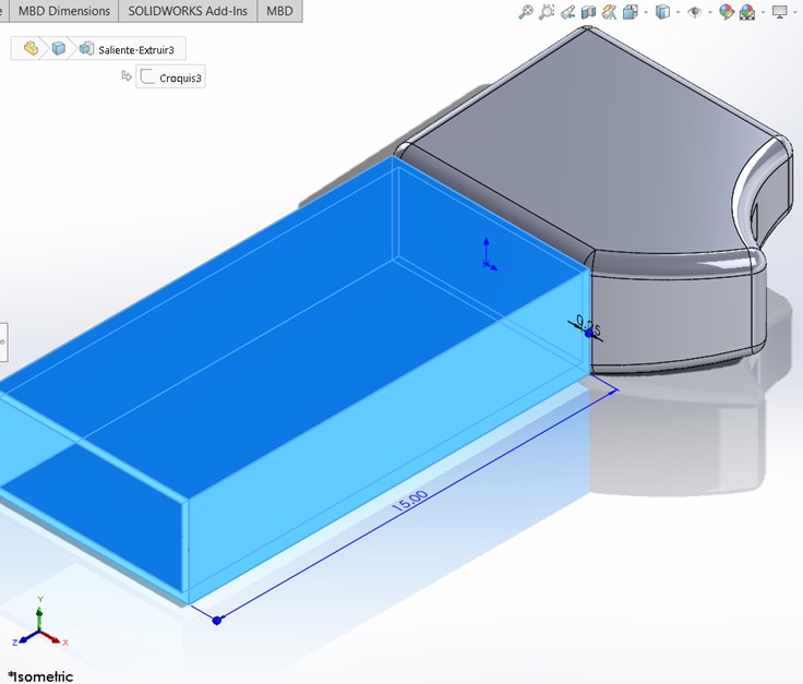
Step 14: Extrude the base for 15cm.
15 / 17
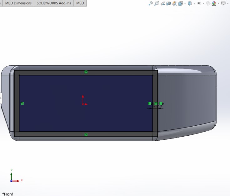
Step 15: Again, go to the front view and select the inside rectangular face and open a sketch. Use the Convert Entities operation and then extrude a cut just enough to make a hole.
16 / 17
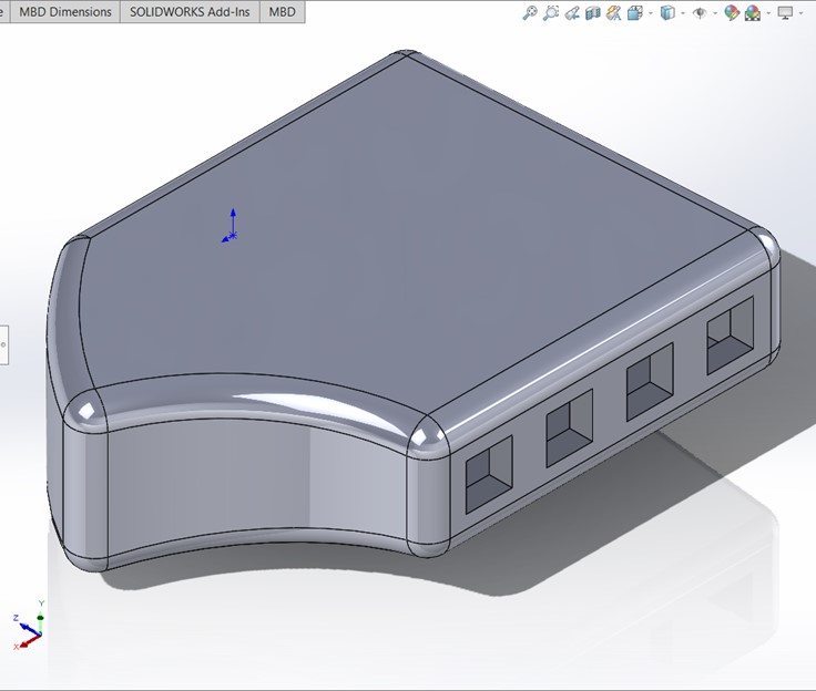
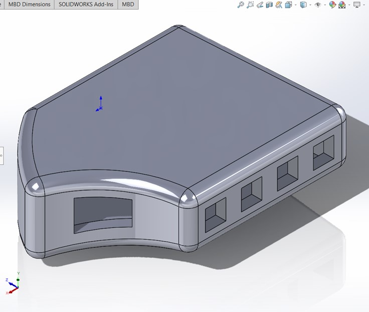
Step 16: Finally, make a Fillet in the corners of the recently extruded base.
17 / 17
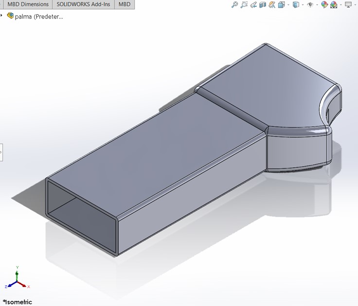
Step 17: Now, you have one of your hands (fingerless), repeat the previous steps to make the second one, just be sure to make it with the opposite orientation.
❮
❯
Finger's Model
1 / 11
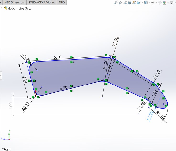
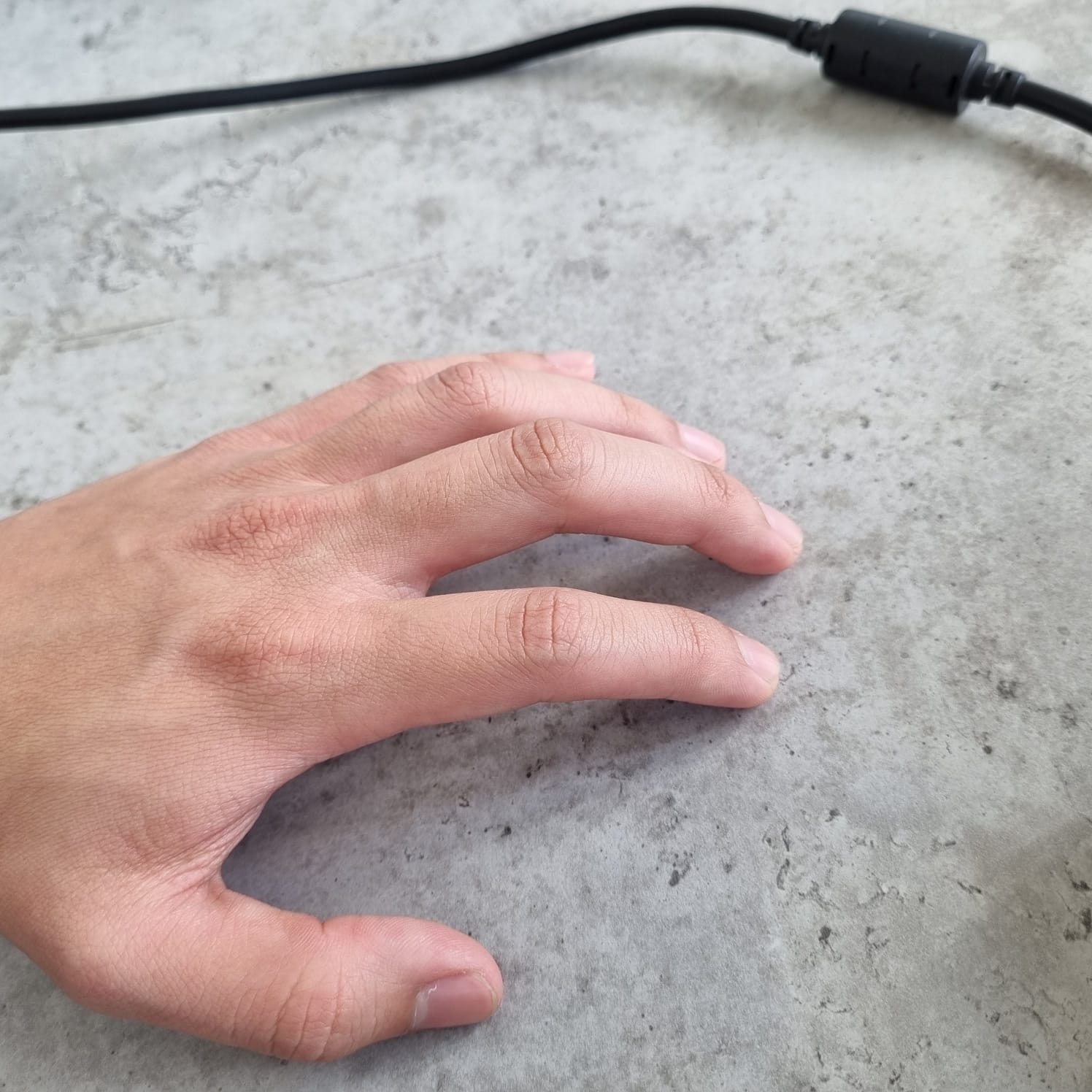
Step 1: Open a sketch in the right plane and draw a set of lines as seen in the image trying make it like a finger. Each finger has different dimensions, so take a ruler and measure yours! I used my index finger as a model for this drawing.
2 / 11
Step 2: Make an extruded base in the mid plane.
3 / 11
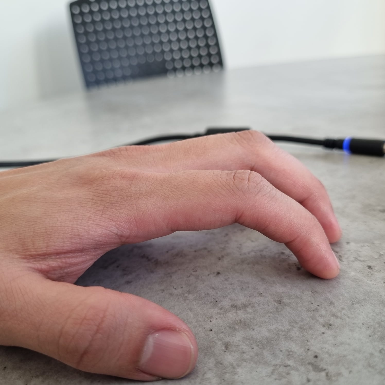
Step 3: Now, we are going to give a more finger kind of shape (my fingers are not so flat). In the top plane open a sketch and draw some contours that would define better the finger.
4 / 11
Step 4: Extrude a cut through all the solid.
5 / 11
Step 5: Make a fillet in all the edges to give a smoother shape.
6 / 11
Step 6: Now we are going to make our finger hollow. Open a sketch in the right plane and use Convert Entities with the inner outline.
7 / 11
Step 7: Extrude a mid-plane cut just enough so that it becomes a cavity.
8 / 11

Step 8: Select the rectangle seen from the front view and create a sketch on that face.
9 / 11
Step 9: Use the Convert Entities operation.
10 / 11
Step 10: Extrude a cut just enough to make an opening to the cavity made before.
11 / 11
Step 11: Finally, you will have a hollow finger. Now repeat the steps but adapting the dimensions to your other fingers.
❮
❯
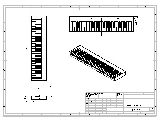
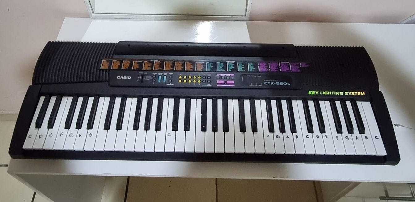
Piano's model.
1 / 11
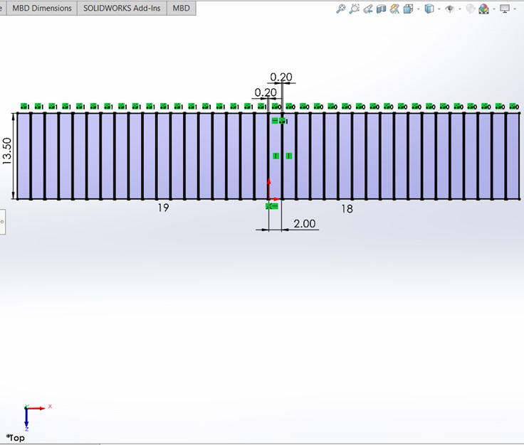
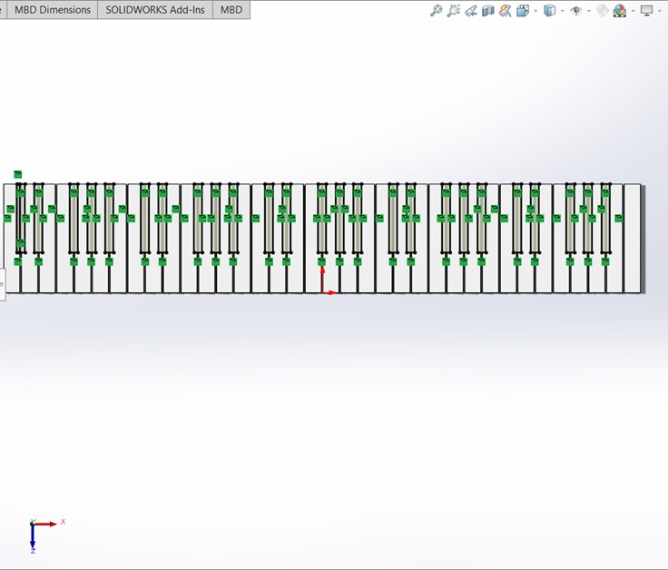
Step 1: Open a sketch in the top plane and draw a linear pattern of the white piano keys.
2 / 11
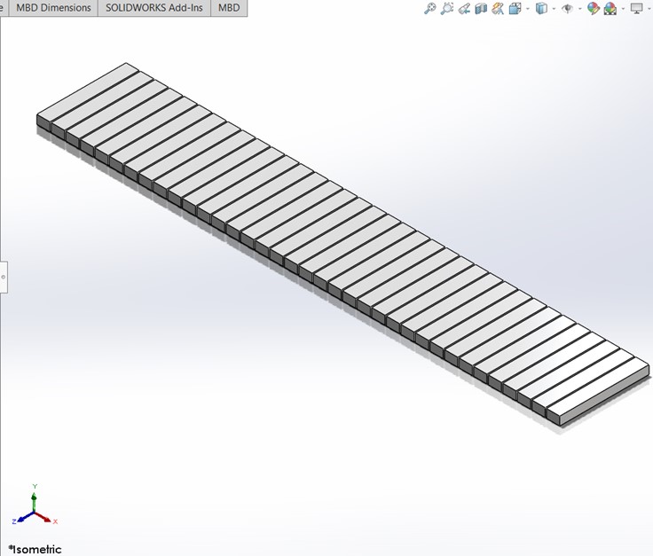
Step 2: Extrude the rectangles 1.30cm.
3 / 11
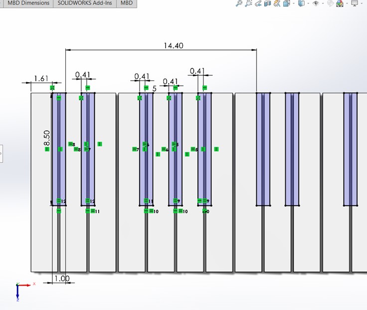
Step 3: Create a sketch over one of the faces of the white keys and then draw the black keys.
4 / 11
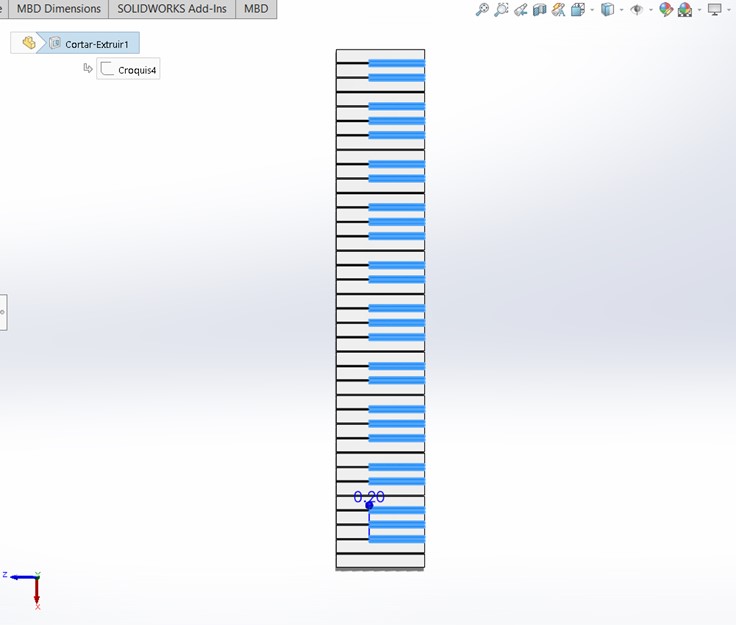
Step 4: Extrude a cut of 0.20cm.
5 / 11
Step 5: Over the previously chopped up faces, make a sketch and Convert Entities over all the black key rectangles.
6 / 11

Step 6: Extrude the rectangles 1.20cm.
7 / 11
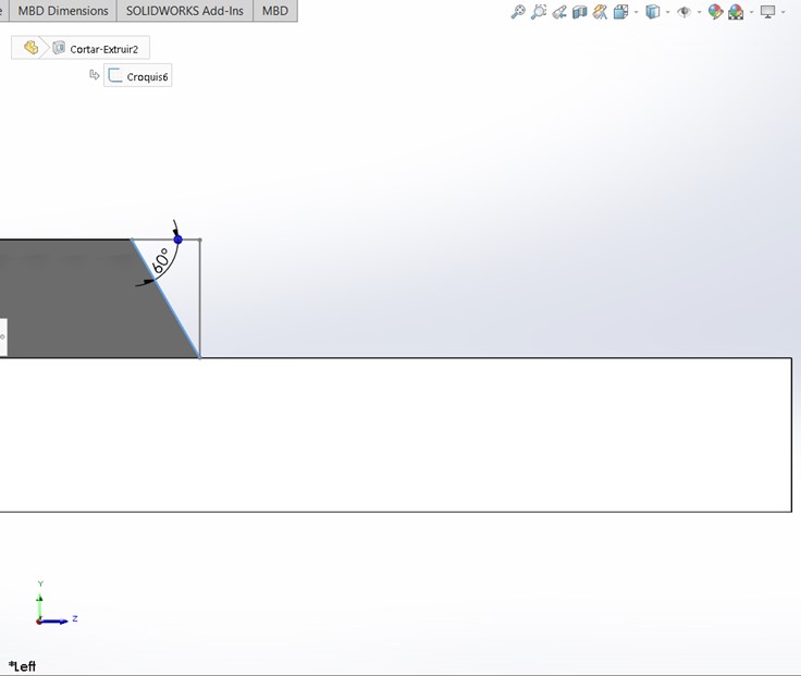
Step 7: Make a chamfer of 60° on the black keys.
8 / 11
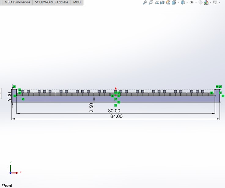
Step 8: In the front plane draw the base of the keyboard.
9 / 11
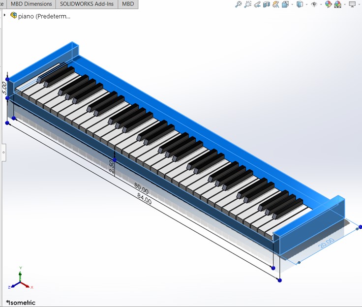
Step 9: Extrude the figure 20cm.
10 / 11
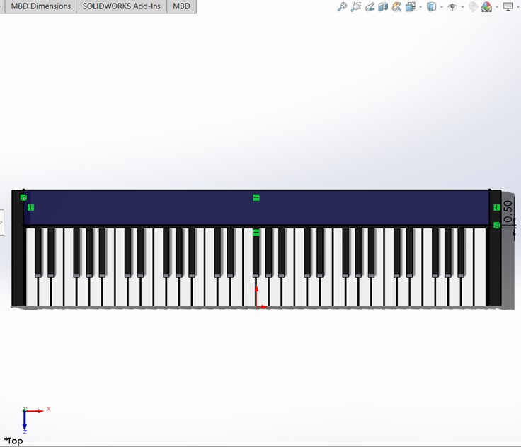
Step 10: Draw a rectangle on the top face of the base and extrude it to match the lateral walls.
11 / 11
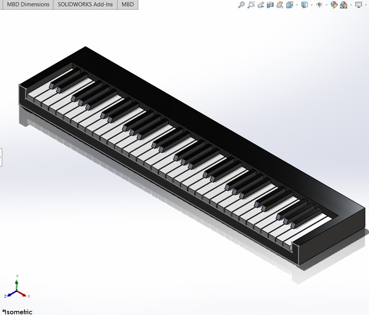
Step 11: Now, you have a model of a keyboard piano.
❮
❯
2D Sketches
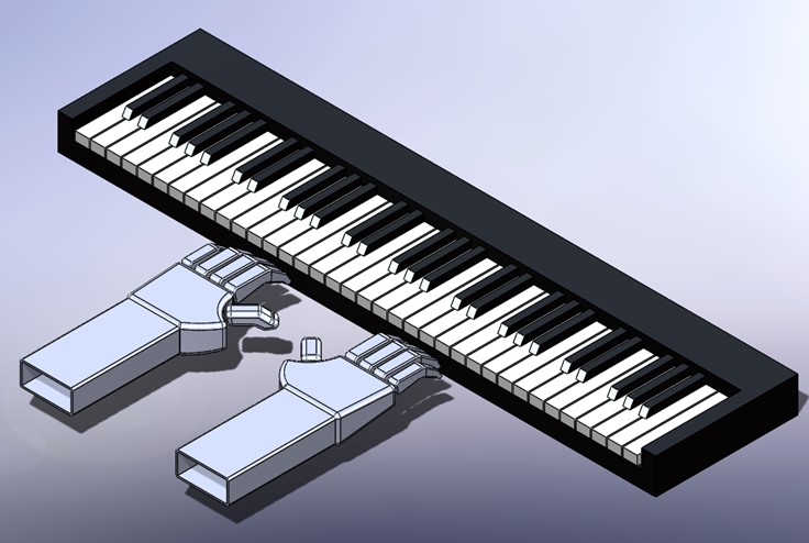
Final Assembly
Assembly of the hands, fingers, and piano keyboard.
2D Design using Illustrator
Open Illustrator and create a New Document
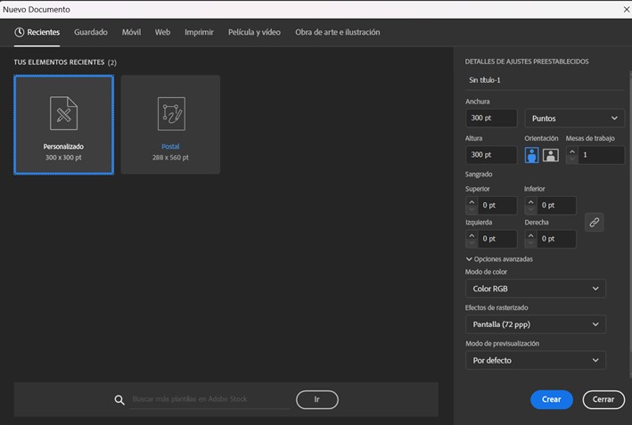
You can work with different options, like adding text, figures, and drawings.
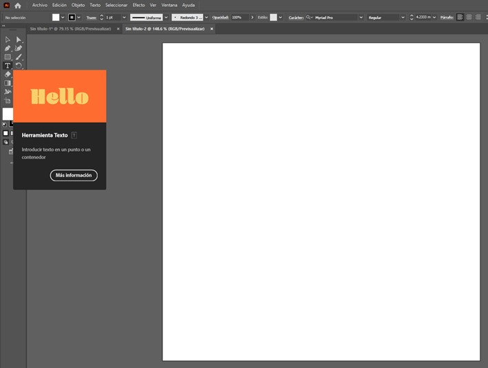
Here, I share you a sketch done in Illustrator for my project Pianonator.

You can download the parts here:
CAD Files - Pianonator