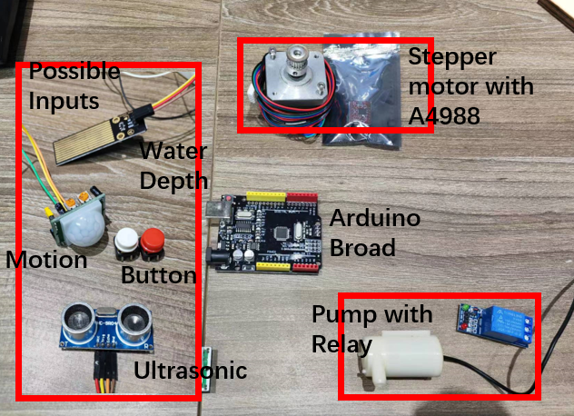
Appearance
Final Project - Dog Feeder
Motivation
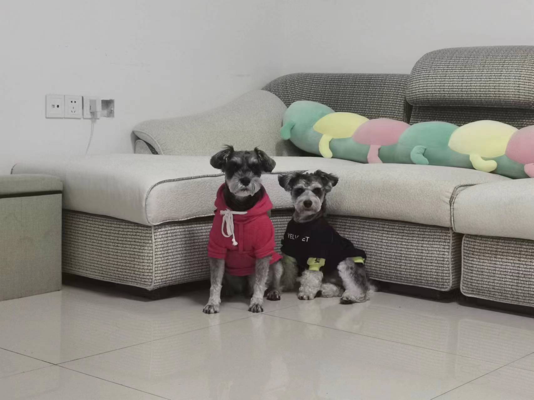
I have two puppies in my house, but I often miss feeding them on time because I'm busy. Therefore I plan to build a remote-controlled auto-dog-feeder.
Idea Sketch
The picture below shows the original design concepts of my dog feed machine.
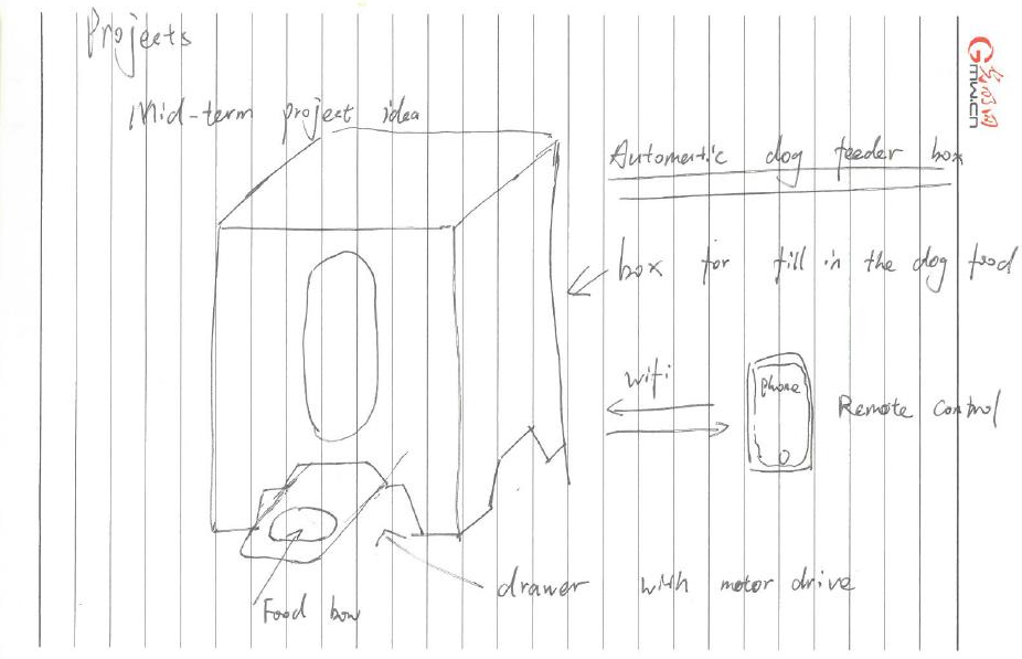
This dog feeder consists of 4 parts:
- A box containing the dog food.
- A drawer drove by a simple motor.
- A control board with WiFi access.
- A user interface on phone for remote control.
After weeks of learning I have adjusted my design concepts as below.
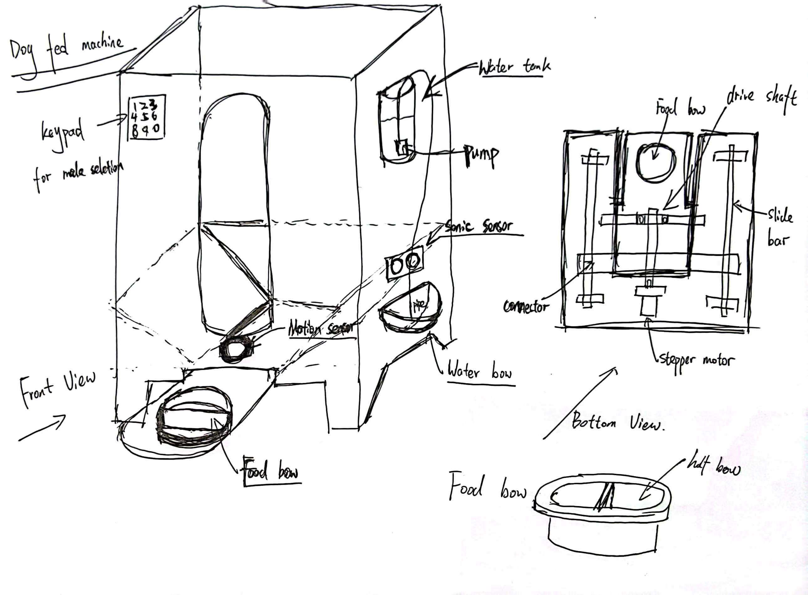
At this stage I have made the following changes:
- The remote control function were realized through WIFI controlled with a phone application.
- A motion sensor/ultrasonic sensor was used to control the , so once the dog is moving around the feeder gate then the motor will push out the food bow for dog to eat.
- Add a water feed module (ie. A pump controlled by an ultrasonic sensor/ water depth sensor.)
- Add a keypad or buttons input module to select how much food would be feed to the dog.(Half Bow by sending out half of the food bow or Full Bow by sending out the entire food bow.)
Structure Construction
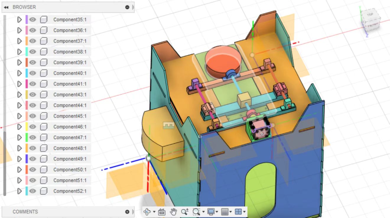
Structural design, cutting and assemble of the feeder box was done in week 2 and 3.

Mechanical Design
The overall mechanical design was shown as picture below.
Electronics Design
At first I planed to use the broad produced in output device week (using XIAO as MCU) to drive a 28 motor to push food to my dog however the torque it generates is not enough.
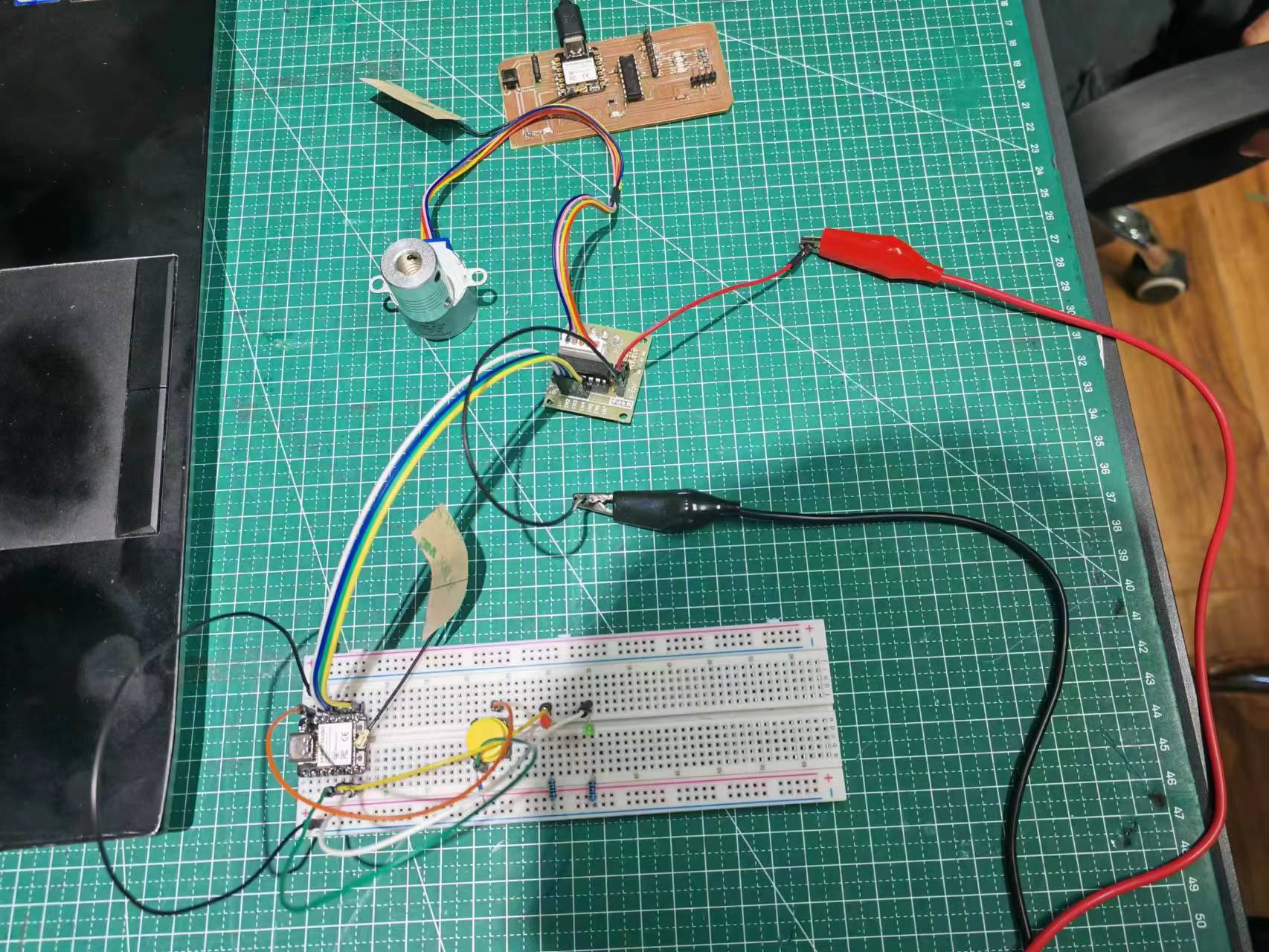
Therefore current electronic elements used include:
- An arduino control broad.
- A stepper motor with A4988 controller.
- A ultrasonic sensor for detecting the dogs approching water bow.
- A motion sensor for detecting the dogs are moving around the food gate.
- A water pump control by a relay.
- A keypad or button for fed mode selection (full bow or half bow).
