Appearance
Embedded programming
This week I have mainly studied about how to use Arduino UNO. I have browse through the datasheet of my Arduino UNO and learned programmed a microcontroller board. I have also compared the Arduino UNO and the Raspberry Pi architecture.
Group Work 2023 & 2025 - Features & Layout for different architecture
Assignment: Demonstrate and compare the toolchains and development workflows for available embedded architectures
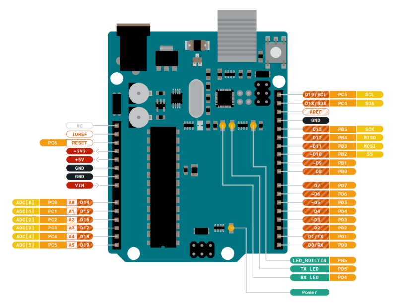
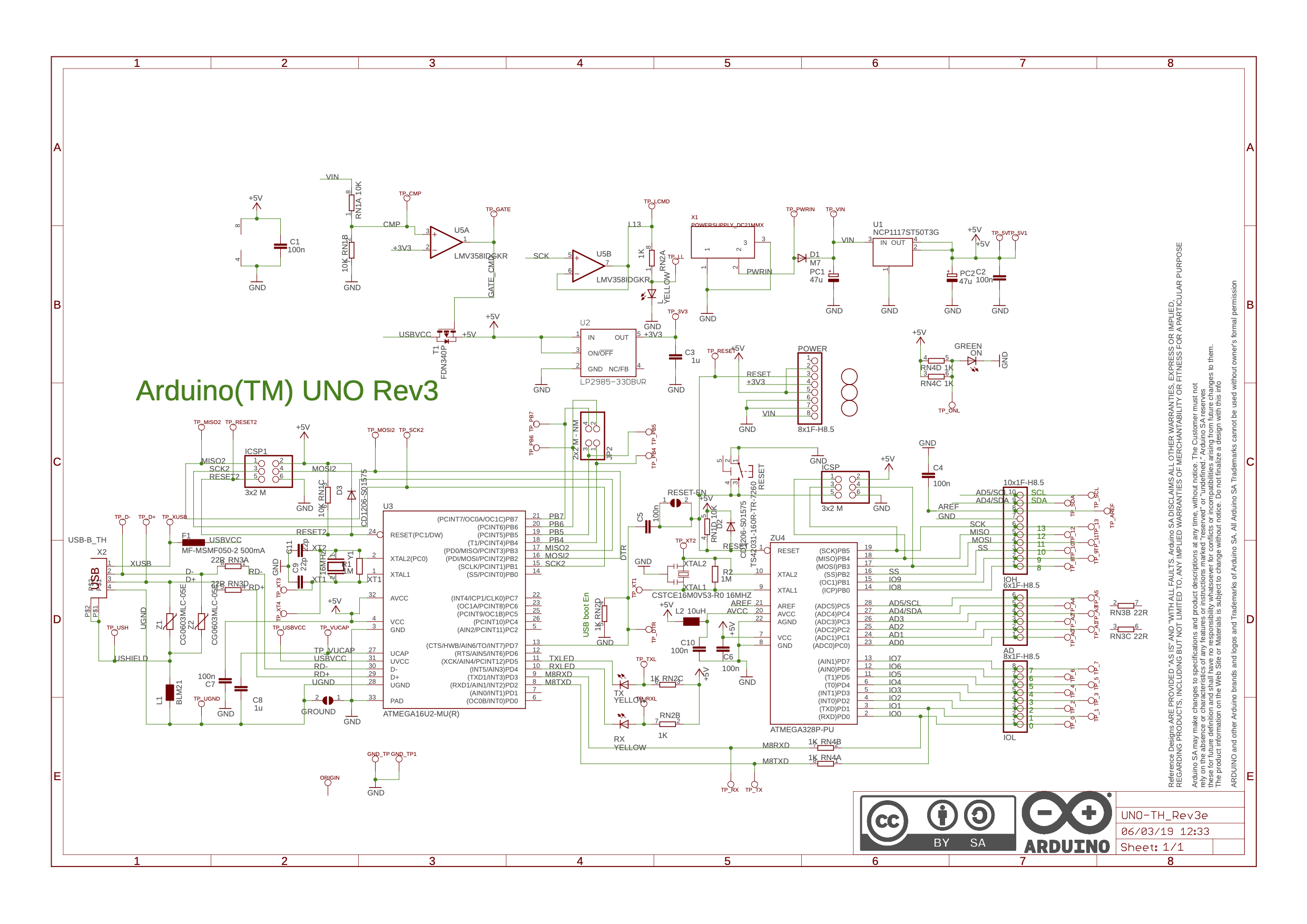
Arduino UNO R3
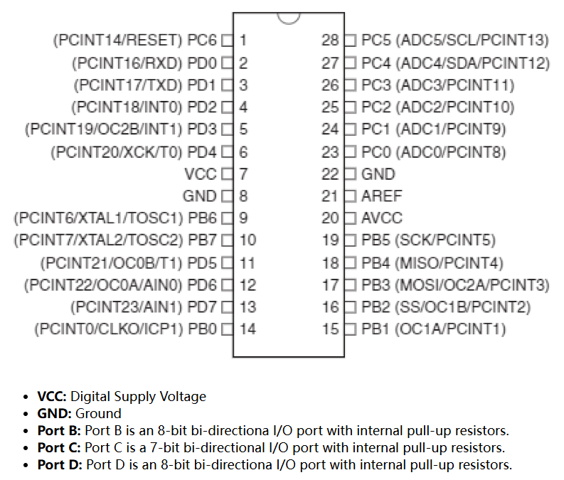
The Arduino UNO R3 uses Atmega328P-PU as core MCU, the key features & layouts is listed below. See Datasheet.
- Name: Arduino UNO
- Microcontroller: Atmega328P-PU
- Operating Voltage: 5V
- Input Voltage: 7-20V
- Number of GPIO Pins: 20
- Digital Pins: 14
- PWM Pins: 6
- Analog Input Pins: 6
- I2C Ports: 1
- UART Ports: 1
- SPPI Ports: 1
- Flash Memory: 32 KB of which 0.5 KB used by bootloader
- SRAM: 2 KB
- EEPROM: 1 KB
- Clock Speed: 16 MHz
The detailed PCB layout of Arduino UNO the board is shown as below.
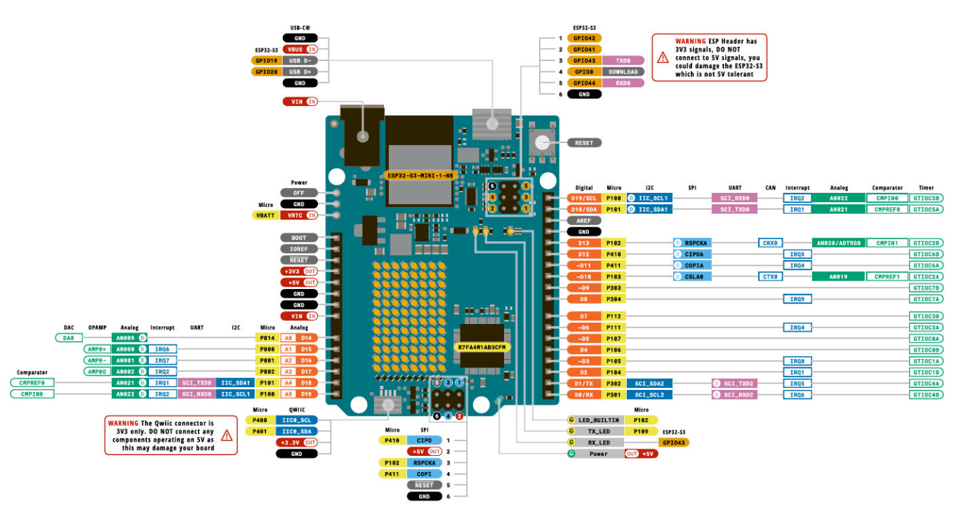
Arduino UNO R4 for Fab2025
The core MCU of the Arduino Uno R4 is the Renesas RA4M1. This chip is based on the ARM Cortex-M4 architecture, runs at a frequency of 48MHz, and features 32KB SRAM and 256KB flash memory. Compared to the Uno R3, the processor has been upgraded to a 32-bit 48MHz Renesas RA4M1, significantly improving performance. The SRAM has increased from 2KB to 32KB, and flash memory from 32KB to 256KB, providing more space for complex applications and data processing. See Datasheet.
- Name: Arduino UNO
- Microcontroller: Renesas RA4M1 (Arm® Cortex®-M4)
- Operating Voltage: 5V
- Input Voltage: 6-24V
- Number of GPIO Pins: 20+ (varies slightly with model)
- Digital Pins: 14
- PWM Pins: 6
- Analog Input Pins: 6
- I2C Ports: 1
- UART Ports: 1
- SPI Ports: 1
- Flash Memory: 256 KB
- SRAM: 32 KB
- EEPROM: Emulated in Flash
- Clock Speed: 48 MHz
- Additional Features (WiFi model only):
- Built-in Wi-Fi (ESP32-S3 coprocessor)
- Qwiic/I²C connector for quick sensor integration
- USB-C port
- Real-Time Clock (RTC)
- CAN Bus support
The detailed PCB layout of the Arduino UNO R4 board (Minima or WiFi) differs from R3 but maintains backward compatibility with existing shields.

The Arduino UNO R4 is powered by the Renesas RA4M1 microcontroller, which represents a significant architectural upgrade from the AVR-based ATmega328P used in the UNO R3. The RA4M1 is based on a 32-bit Arm® Cortex®-M4 core with a built-in Floating Point Unit (FPU), offering enhanced performance, scalability, and efficiency for modern embedded applications. Key Architectural Features include:
- Core: Arm Cortex-M4
- Architecture: 32-bit RISC
- Clock Frequency: Up to 48 MHz
- Floating Point Support: Single-precision FPU
- Instruction Set: Thumb-2 (dense 16/32-bit instruction set for code efficiency)
- Power Efficiency: ARM low-power modes supported, with multiple sleep and standby configurations
- Bus System: Advanced High-performance Bus (AHB) for faster peripheral and memory access
- Interrupt System: Nested Vectored Interrupt Controller (NVIC) with up to 64 external interrupts
- Memory:
- 256 KB Flash
- 32 KB SRAM
- EEPROM emulated in Flash
- Peripherals Integration:
- I2C, SPI, UART
- ADC (14-bit)
- DAC (12-bit, optional)
- CAN bus (FD-capable)
- Real-Time Clock (RTC)
- Security and Safety:
- Memory Protection Unit (MPU)
- Clock and voltage monitors
Raspberry Pi 4 Model B
The key features & layouts for the Raspberry Pi 4 Model B can be found in Datasheet:
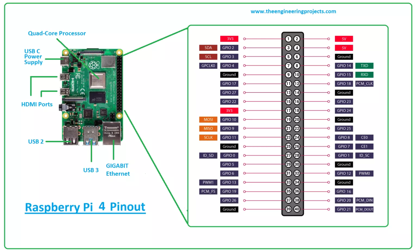
- Name: Raspberry Pi 4 Model B
- Microcontroller: Broadcom BCM2711
- Operating Voltage: 5V (via USB-C)
- Input Voltage: 5V (recommended)
- Number of GPIO Pins: 40
- Digital Pins: 40 (all GPIO pins are digital)
- PWM Pins: 2 PWM channels on 4 GPIO pins (GPIO 12, 13, 18, 19)
- Analog Input Pins: None (requires external ADC for analog input)
- I2C Ports: 1 (two I2C buses available)
- UART Ports: 1 (plus a secondary UART available)
- SPI Ports: 1
- Flash Memory: None (uses microSD card for storage)
- SRAM: 1 GB, 2 GB, or 4 GB RAM options (LPDDR4)
- EEPROM: Not applicable (external storage through microSD)
- Clock Speed: Up to 1.5 GHz (quad-core ARM Cortex-A72)
Group Work 2023 & 2025 - Comparison of different architecture
Compare the performance and development workflows for Arduino UNO R3\R4 and the Raspberry Pi 4B architecture.
🧠 Performance
Processing Power
Arduino UNO R3:
Features an 8-bit ATmega328P microcontroller running at 16 MHz. Suitable for simple tasks, sensor control, and real-time logic with minimal overhead.Arduino UNO R4:
Upgraded to a 32-bit Arm Cortex-M4 microcontroller (Renesas RA4M1) running at 48 MHz with a floating point unit (FPU). Offers a major performance boost over R3, enabling more complex calculations and peripheral control.Raspberry Pi 4B:
A full-fledged single-board computer with a quad-core ARM Cortex-A72 processor @ 1.5 GHz. Can handle multitasking, media processing, and run a full OS.
Memory
Arduino UNO R3:
2 KB SRAM, 32 KB flash, 1 KB EEPROM. Limited memory restricts application complexity.Arduino UNO R4:
32 KB SRAM, 256 KB flash, EEPROM emulated in flash. Allows for more complex firmware and data handling than R3.Raspberry Pi 4B:
1 GB to 8 GB of LPDDR4 RAM. Supports demanding applications, multitasking, databases, and multimedia.
I/O Capabilities
Arduino UNO R3 & R4:
Both provide 14 digital I/O, 6 analog inputs, and support I2C, SPI, UART. R4 adds support for CAN bus, DAC, and Real-Time Clock (WiFi model). Great for direct hardware and sensor interfacing.Raspberry Pi 4B:
Offers 40 GPIO pins, supports I2C, SPI, UART, plus HDMI, USB, Ethernet, CSI/DSI interfaces. More suitable for high-level peripherals and external modules.
💻 Development Workflows
Programming Environment
Arduino UNO R3 & R4:
Programmed using the Arduino IDE or other Arduino-compatible platforms. Code is written in simplified C/C++, compiled, and flashed via USB. Serial Monitor aids in debugging.Raspberry Pi 4B:
Supports development in Python, C/C++, Java, etc. Code can be written using IDEs like Thonny, VS Code, or even directly on the Pi. SSH and VNC allow remote programming.
Operating System
Arduino UNO R3 & R4:
No operating system. Firmware runs directly on bare-metal hardware. Deterministic and predictable timing, ideal for real-time control.Raspberry Pi 4B:
Runs full Linux-based OS (typically Raspberry Pi OS). Supports multitasking, services, daemons, GUIs, and system-level operations.
Libraries and Community Support
Arduino UNO R3:
Mature ecosystem with extensive community support and libraries tailored for hardware control.Arduino UNO R4:
Growing library support (due to newer architecture), with official support from Arduino and increasing third-party contributions.Raspberry Pi 4B:
Massive community and rich library support across domains like AI, networking, media, and IoT.
🔧 Application Use Cases
| Use Case | UNO R3 | UNO R4 | Raspberry Pi 4B |
|---|---|---|---|
| Simple sensor control | ✅ | ✅ | ✅ |
| Real-time applications | ✅ | ✅ (better precision & FPU) | ⚠️ (non-deterministic timing) |
| Robotics & embedded systems | ✅ | ✅✅ | ⚠️ (better with co-processing) |
| Signal processing / math | ❌ | ✅ (FPU helps) | ✅✅✅ |
| Web server or GUI applications | ❌ | ❌ | ✅✅✅ |
| Machine learning or AI inference | ❌ | ⚠️ (possible, but limited) | ✅✅✅ |
| Media streaming / HDMI output | ❌ | ❌ | ✅✅✅ |
📝 Summary
The Arduino UNO R3 is ideal for simple, real-time embedded projects with tight resource constraints.
The Arduino UNO R4 bridges the gap with better processing power, memory, and peripheral support, making it suitable for more advanced control systems and moderate embedded applications.
The Raspberry Pi 4B is a full Linux computer, ideal for high-level applications, multitasking, networking, and projects requiring significant computation or storage.
Each platform suits different needs:
- R3: Pure embedded control with minimal resources.
- R4: Enhanced embedded system with more modern MCU features.
- Pi 4: Embedded Linux computer with full-stack capabilities.
Physical Light Experiment Comparison
Arduino LED Blinking Experiment – Simple Steps
Objective
Make an LED blink on and off using an Arduino board.
Materials Needed
- 1 × Arduino board (e.g., Uno)
- 1 × LED
- 1 × 220Ω resistor
- Breadboard and jumper wires
- USB cable and a computer with Arduino IDE installed
Wiring Instructions
Connect the LED:
- Long leg (anode) → Digital Pin 13
- Short leg (cathode) → One end of the resistor
- Other end of the resistor → GND (Ground)
Check your connections carefully.
Code (Upload with Arduino IDE)
void setup() {
  pinMode(13, OUTPUT); // Set pin 13 as output
}

void loop() {
  digitalWrite(13, HIGH); // Turn LED on
  delay(1000);            // Wait 1 second
  digitalWrite(13, LOW);  // Turn LED off
  delay(1000);            // Wait 1 second
}
Raspberry Pi LED Blinking Experiment – Simple Steps
Objective
Control an LED to blink using Raspberry Pi GPIO and Python.
Materials Needed
- Raspberry Pi (any model with GPIO, e.g. Pi 4 or Pi Zero)
- 1 × LED
- 1 × 330Ω or 220Ω resistor
- Breadboard and jumper wires
- Monitor, keyboard, and mouse (or SSH access)
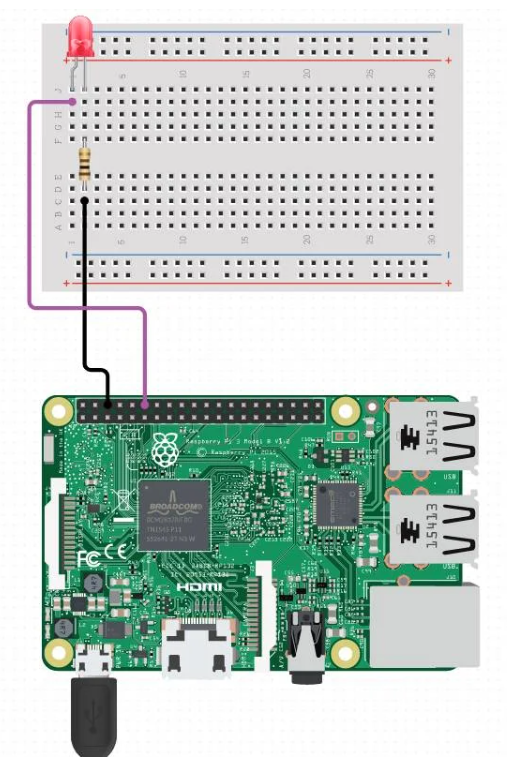
Wiring Instructions (GPIO Example)
- Connect the LED:
- Long leg (anode) → GPIO17 (Pin 11)
- Short leg (cathode) → One end of resistor
- Other end of resistor → GND (Pin 6)
Python Code (Run on Raspberry Pi)
- Open Terminal or Thonny Python IDE
- Create a new file
blink.pyand paste:
python
import RPi.GPIO as GPIO
import time

# Setup
GPIO.setmode(GPIO.BCM)     # Use BCM pin numbering
GPIO.setup(17, GPIO.OUT)   # Set GPIO17 as output

# Loop to blink LED
try:
    while True:
        GPIO.output(17, GPIO.HIGH)  # LED on
        time.sleep(1)               # Wait 1 second
        GPIO.output(17, GPIO.LOW)   # LED off
        time.sleep(1)               # Wait 1 second
except KeyboardInterrupt:
    GPIO.cleanup()                 # Clean up on Ctrl+C
Run the Script
In terminal, navigate to your script folder and run:
sudo apt install python3-rpi.gpio           # Install gpio tool
python3 blink.py                            # Run script
The result can be seen in photo below:
Try Arduino UNO
The first architecture I tried is Arduino UNO. As it is a easier board to get start with.
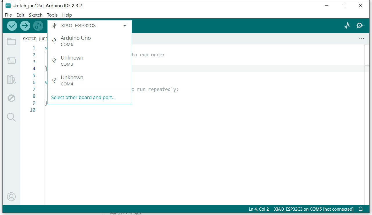
Software
We can download Arduino IDE from [www.arduino.cc] (https://www.arduino.cc/) according to your PC's version and then install by yourself.
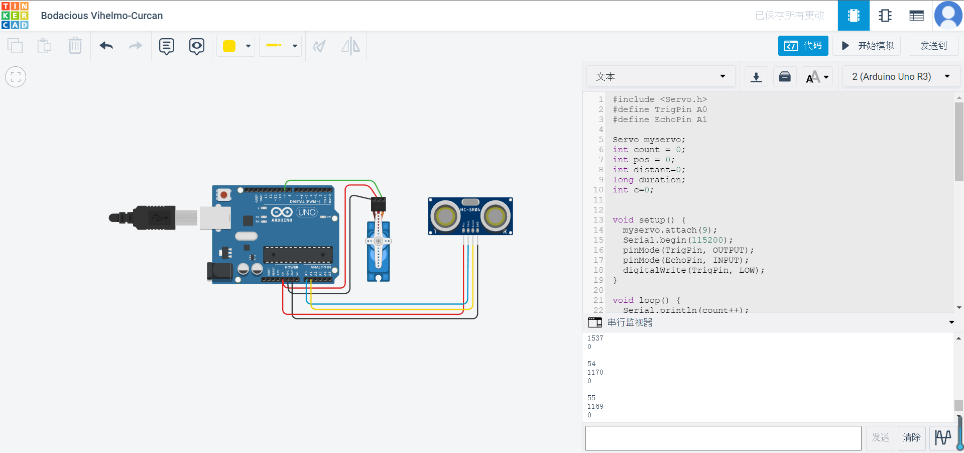
Design and Simulation
TinkerCAD is a great website where you can design and test your circuit online.
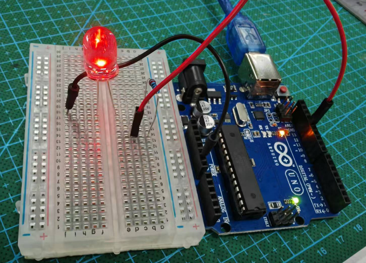
Light Control Experiment
We can use switch to control the circuit, in this case we use pin 7 as input port.
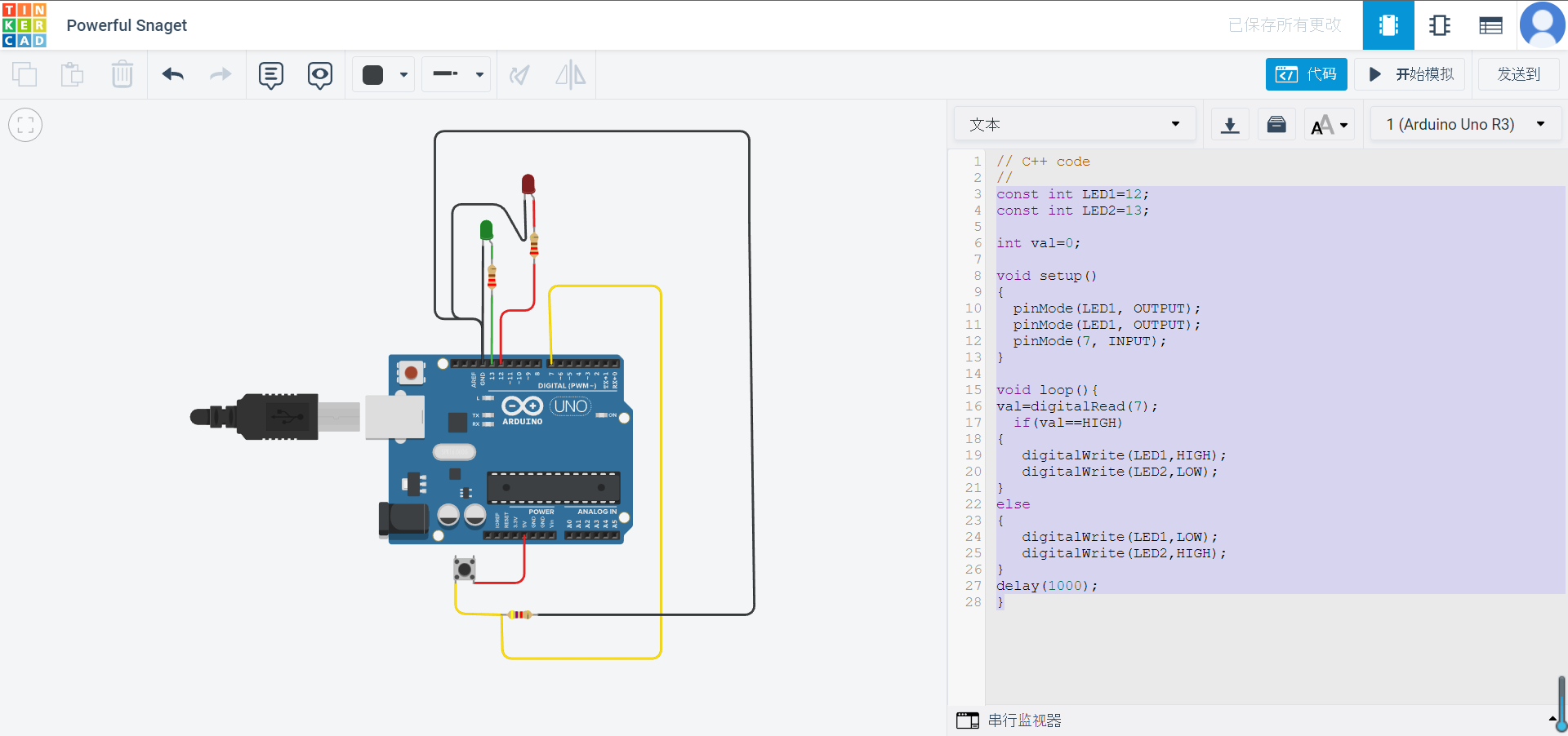
The code for this control loop is as below.
const int LED1=10;
const int LED2=13;
int val=0;
void setup()
{
pinMode(LED1, OUTPUT);
pinMode(LED1, OUTPUT);
pinMode(7, INPUT);
}
void loop(){
val=digitalRead(7);
if(val==HIGH)
{
digitalWrite(LED1,HIGH);
digitalWrite(LED2,LOW);
}
else
{
digitalWrite(LED2,HIGH);
digitalWrite(LED1,LOW);
}
delay(1000);
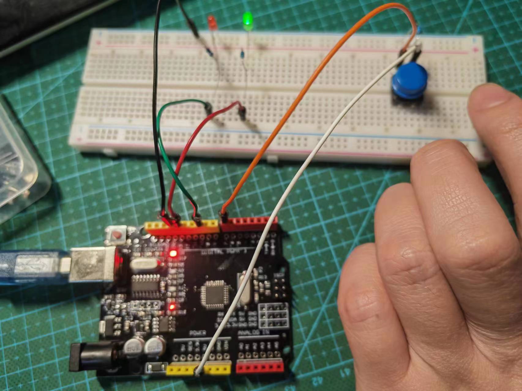
}When the button is pressed,the red light will glow.
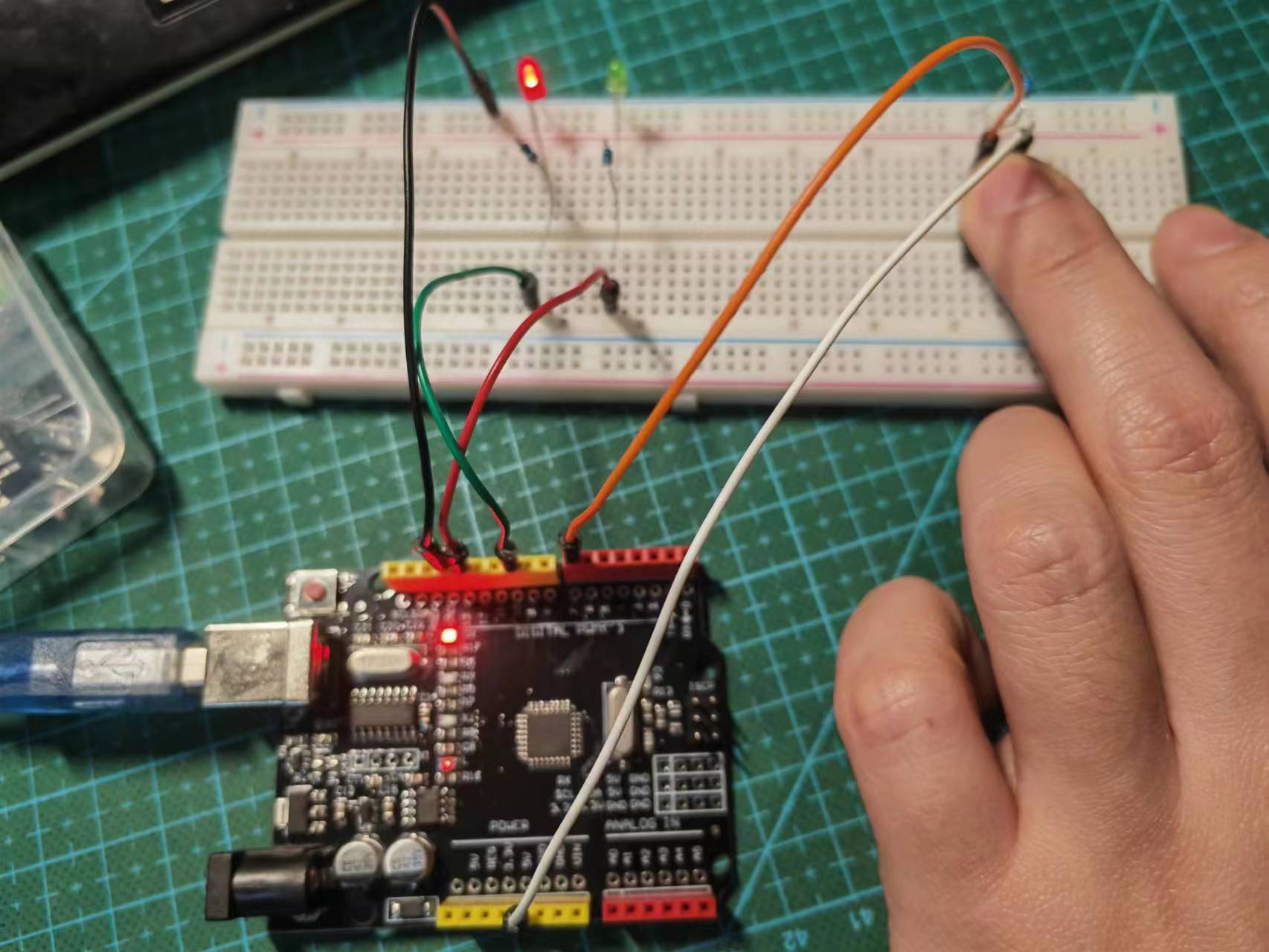
When the button is released, the green light will glow.
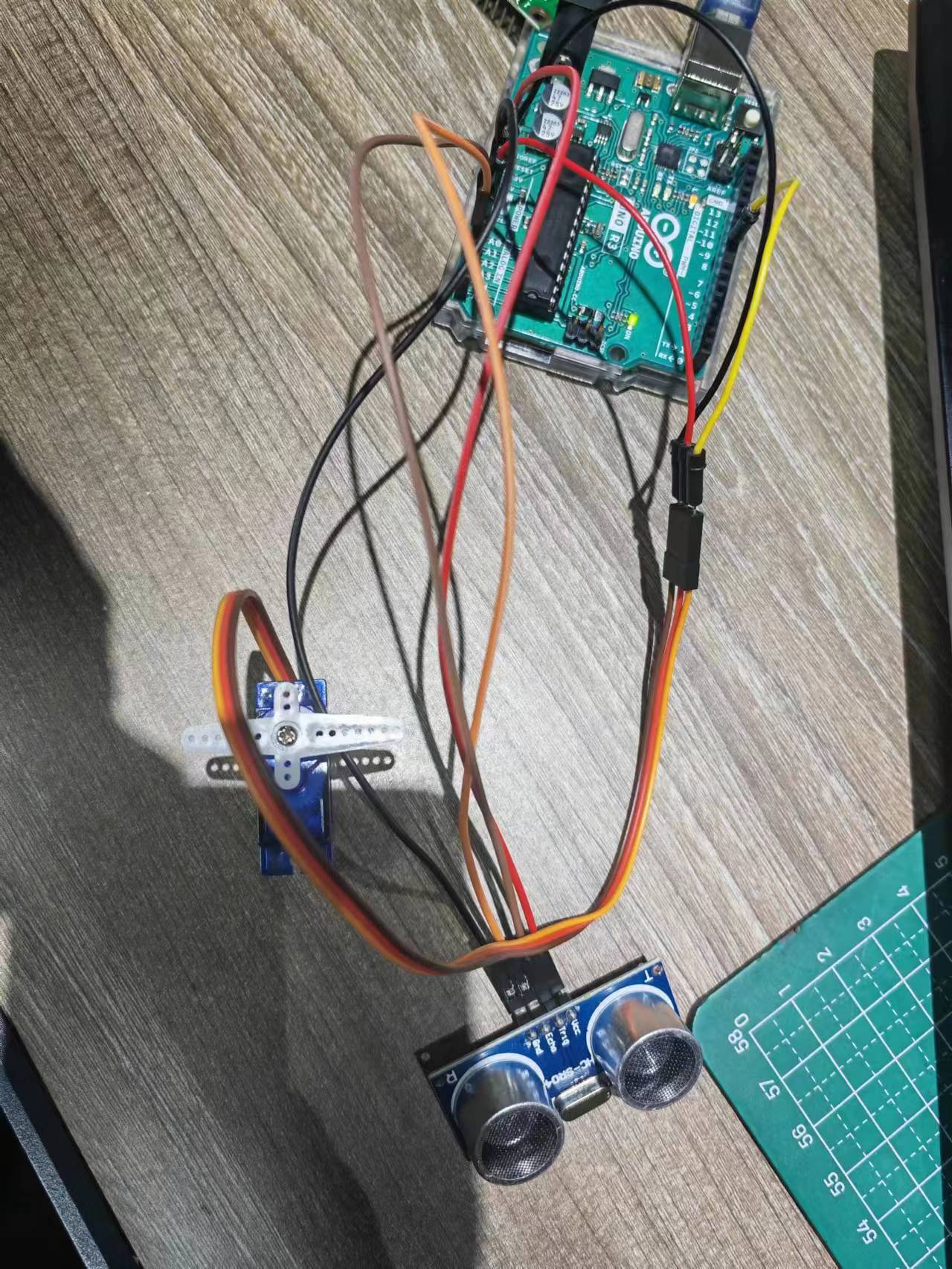
Servo Control with Ultrasonic Sensor Input
In this exercise, i have tried to use ultrasonic sensor as input to trigger a servo motor to rotate. This interaction happens when an object enter or leave the sensor's detection range.
#include <Servo.h>
#define EchoPin A1
#define TrigPin A0
Servo myservo;
int count = 0;
int val;
long duration;
void setup() {
myservo.attach(9);
Serial.begin(115200);
pinMode(TrigPin, OUTPUT);
pinMode(EchoPin, INPUT);
digitalWrite(TrigPin, LOW);
delay(1);
}
void loop() {
Serial.print(count++);
Serial.println("");
Serial.println(getDistance());
Serial.println("");
val=getDistance();
if (val<1023){
val = map(val, 0, 1023, 0, 180);
myservo.write(val);
delay(15);
}
return;
}
long getDistance() {
// trig
digitalWrite(TrigPin, LOW);
delayMicroseconds(2);
digitalWrite(TrigPin, HIGH);
delayMicroseconds(10);
digitalWrite(TrigPin, LOW);
// echo
duration = pulseIn(EchoPin, HIGH); // unit: us
return duration * 0.34029 / 2; // unit: mm
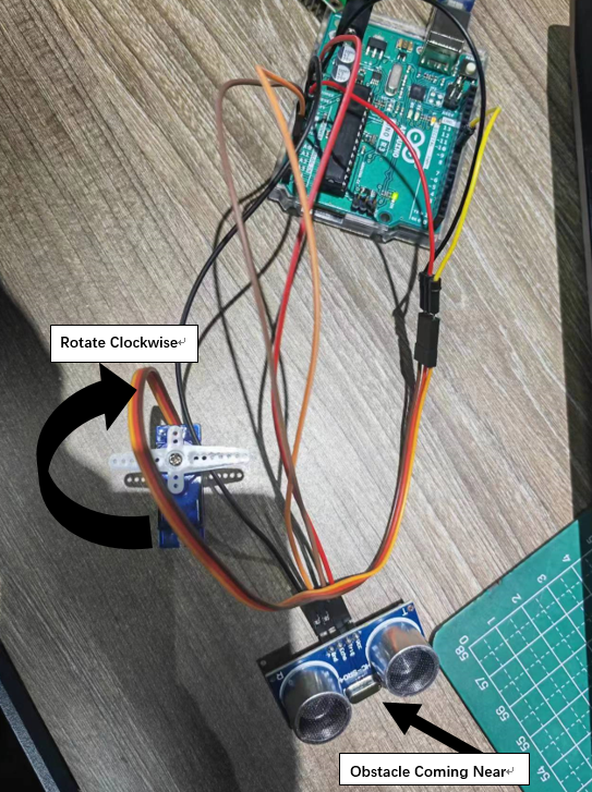
}Final result is that when an obstacle is approching near to the Ultrasonic Sensor then servo motor will rotate 180 degree clockwise, when the obstacle leaves the servo motor will rotate 180 degree anticlockwise.
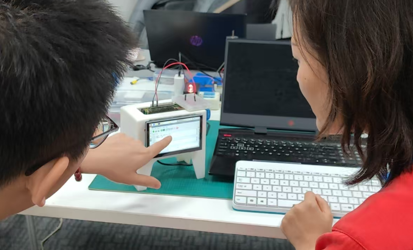
Try Raspberry Pi 4B
In order to compare the performance and development workflows for other architectures, I use Raspberry Pi 4B to light up two LED light, the circuit is connected as below.
The Raspberry Pi 4B I uses as core MCU, the key features on data sheet is listed below.
- Broadcom BCM2711, Quad core Cortex-A72 (ARM v8) 64-bit SoC @ 1.5GHz
- 2GB, 4GB or 8GB LPDDR4-3200 SDRAM (depending on model)
- 2.4 GHz and 5.0 GHz IEEE 802.11ac wireless, Bluetooth 5.0, BLE
- Gigabit Ethernet
- 2 USB 3.0 ports; 2 USB 2.0 ports.
- Raspberry Pi standard 40 pin GPIO header (fully backwards compatible with previous boards)
- 2 × micro-HDMI ports (up to 4kp60 supported)
- 2-lane MIPI DSI display port
- 2-lane MIPI CSI camera port
- 4-pole stereo audio and composite video port
- H.265 (4kp60 decode), H264 (1080p60 decode, 1080p30 encode)
- OpenGL ES 3.1, Vulkan 1.0
- Micro-SD card slot for loading operating system and data storage
- 5V DC via USB-C connector (minimum 3A*)
- 5V DC via GPIO header (minimum 3A*)
- Power over Ethernet (PoE) enabled (requires separate PoE HAT)
- Operating temperature: 0 – 50 degrees C ambient
On Raspberry Pi I have used Python language to program and what I have done is simply shine a LED light with my Raspberry Pi as below.
import RPi.GPIO as GPIO
import time
GPIO.setmode(GPIO.BCM)
GPIO.setwarnings(False)
GPIO.setup(18,GPIO.OUT)
GPIO.setup(15,GPIO.OUT)
print ("LED1 on")
GPIO.output(18,GPIO.HIGH)
time.sleep(1)
print ("LED1 off")
GPIO.output(18,GPIO.LOW)
print ("LED2 on")
GPIO.output(15,GPIO.HIGH)
time.sleep(1)
print ("LED2 off")
GPIO.output(15,GPIO.LOW)
The result is shown as video below.
Communication between both architectures
In this part, I connect an Arduino to a Raspberry Pi and have the Arduino send "Hello from Arduino" to the Raspberry Pi, which will blink an LED upon receiving the command from the Arduino.
Materials Needed:
- Arduino
- Raspberry Pi
- USB cable
- LED
- Resistor
- Breadboard and wires
Steps for communication:
Connect the LED to Pin 11: Connect the longer leg (anode) of the LED to GPIO pin 17 on the Raspberry Pi. Connect the shorter leg (cathode) to a resistor and then to the ground (GND).
Set Up the Raspberry Pi:
Open Python 3 in a new window on the Raspberry Pi. Write and save the following code:
import serial
import RPi.GPIO as GPIO
import time

# Initialize serial communication with Arduino
ser = serial.Serial("/dev/ttyACM0", 9600)
# change ACM number as found from ls /dev/tty/ACM* The ACM number refers to the specific device identifier for a USB-connected serial device on a Unix-like operating system, such as Linux or macOS. When you connect a USB device to your computer, it is assigned a unique identifier like /dev/ttyACM0, /dev/ttyACM1, etc. The number at the end (0, 1, etc.) increments based on the order in which devices are connected.
ser.baudrate = 9600

# Define a function to blink an LED
def blink(pin):
    GPIO.output(pin, GPIO.HIGH)  # Turn the LED on
    time.sleep(1)                # Wait for 1 second
    GPIO.output(pin, GPIO.LOW)   # Turn the LED off
    time.sleep(1)                # Wait for 1 second
    return

# Set up GPIO using Board numbering
GPIO.setmode(GPIO.BOARD)
GPIO.setup(17, GPIO.OUT)  # Set pin 17 as an output pin

# Main loop
while True:
    # Read a line from the serial input
    read_ser = ser.readline().decode('utf-8').strip()
    print(read_ser)  # Print the received message
    # Check if the received message matches "Hello From Arduino!"
    if read_ser == "Hello From Arduino!":
        blink(17)  # Blink the LED connected to pin 17
Set Up the Arduino: Open Arduino IDE and upload the following code to Arduino:
String data = "Hello From Arduino!";

void setup() {
    Serial.begin(9600);
}

void loop() {
    Serial.println(data);  // data that is being Sent
    delay(200);
}
Enable Serial and I2C on Raspberry Pi: Open raspi-config and enable both Serial and I2C interfaces.

Install Required Libraries:
sudo apt-get install python-serial
sudo pip install pyserial
Connect Arduino to Raspberry Pi: Use a USB cable to connect the Arduino to the Raspberry Pi. Execute ls /dev/tty* in the terminal and find a line like /dev/ttyACM0 or similar.
Update the Python Code: Update the line ser = serial.Serial("/dev/ttyACM1", 9600) to match the ACM number you found, e.g., ser = serial.Serial("/dev/ttyACM0", 9600)
Run the Python Program: Now run the Python program you created. You should see "Hello From Arduino!" in the Python terminal, and the LED should blink!
The result is shown as video below.