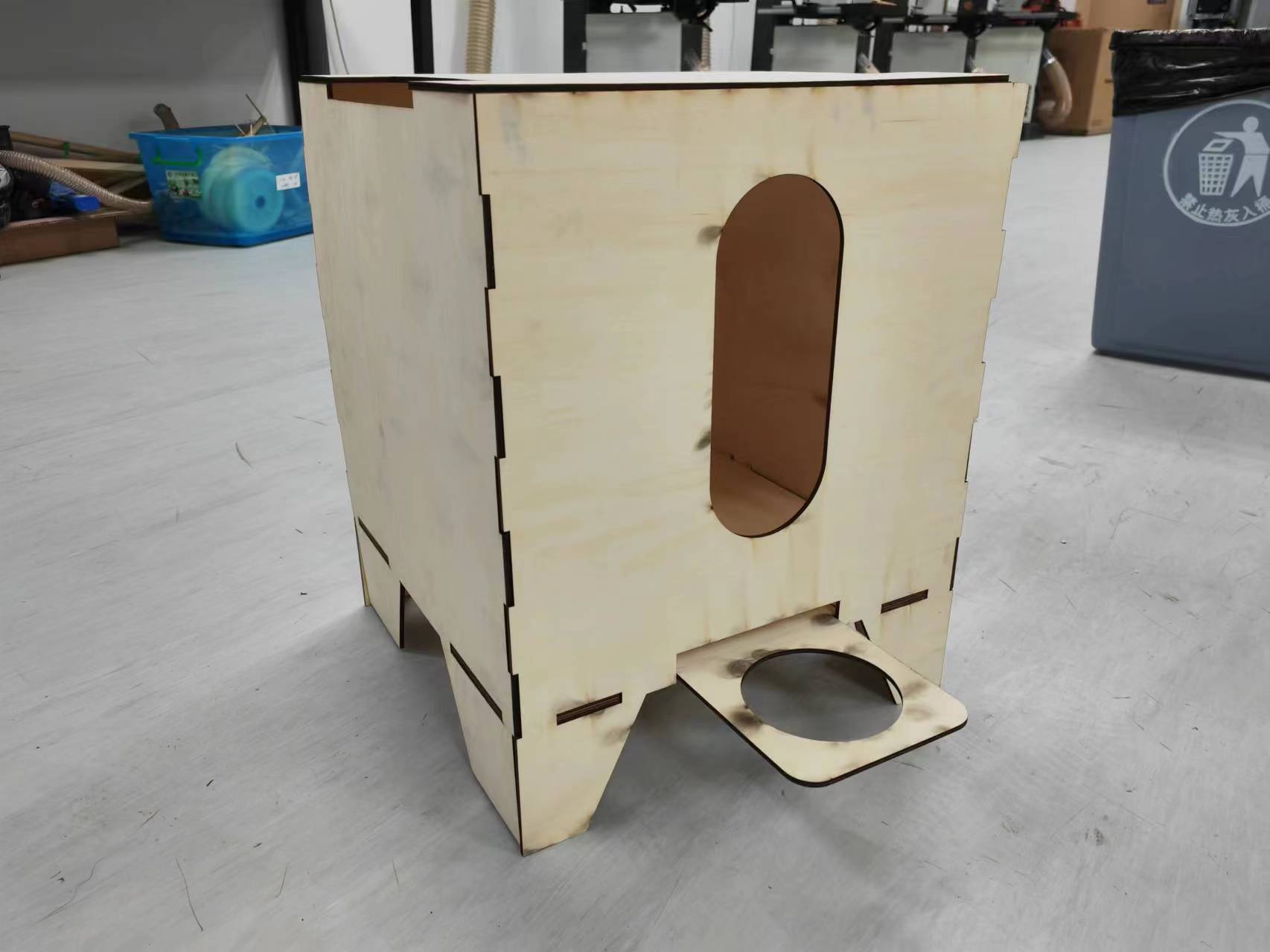
Appearance
Computer Aid Cutting
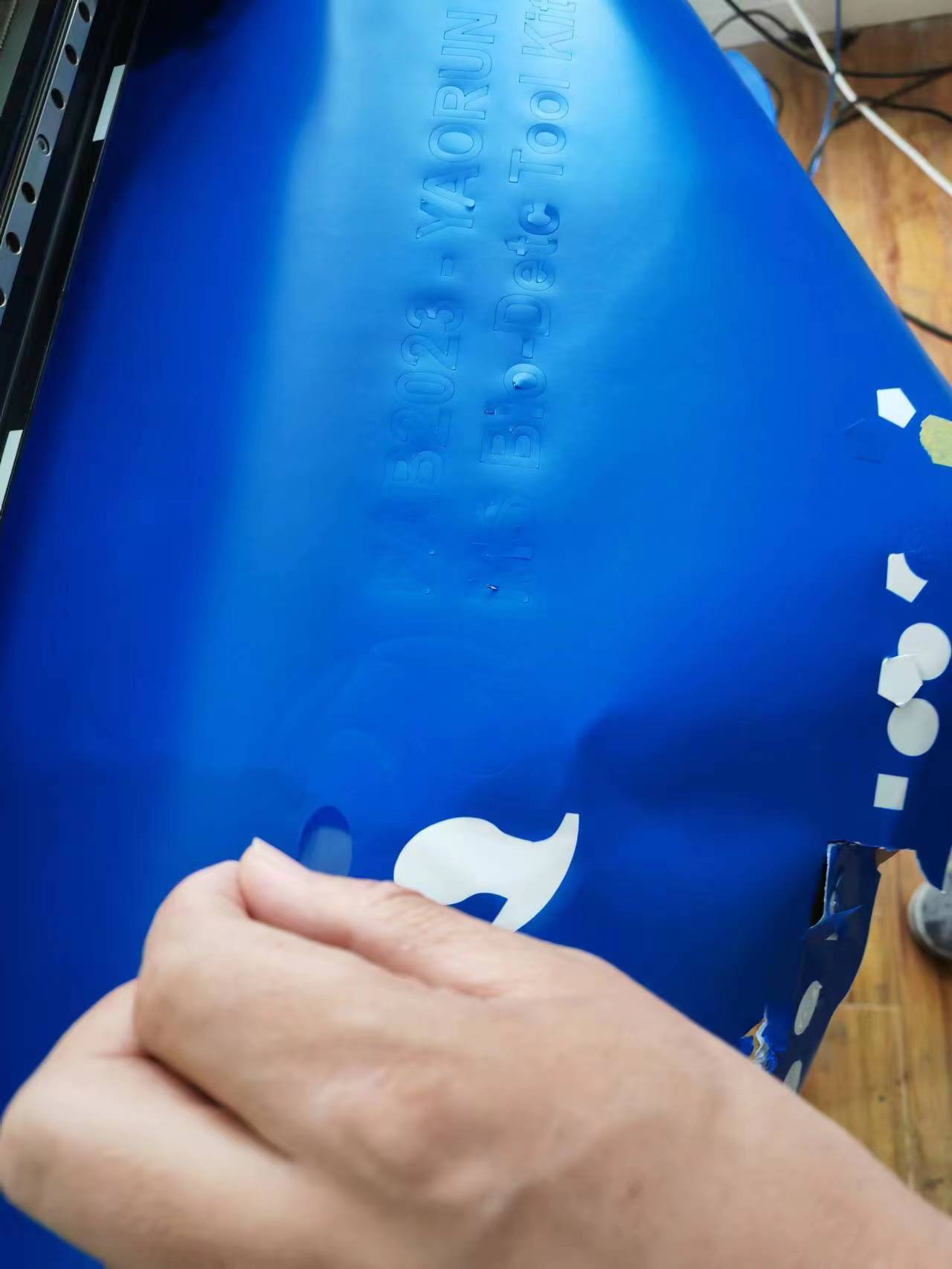
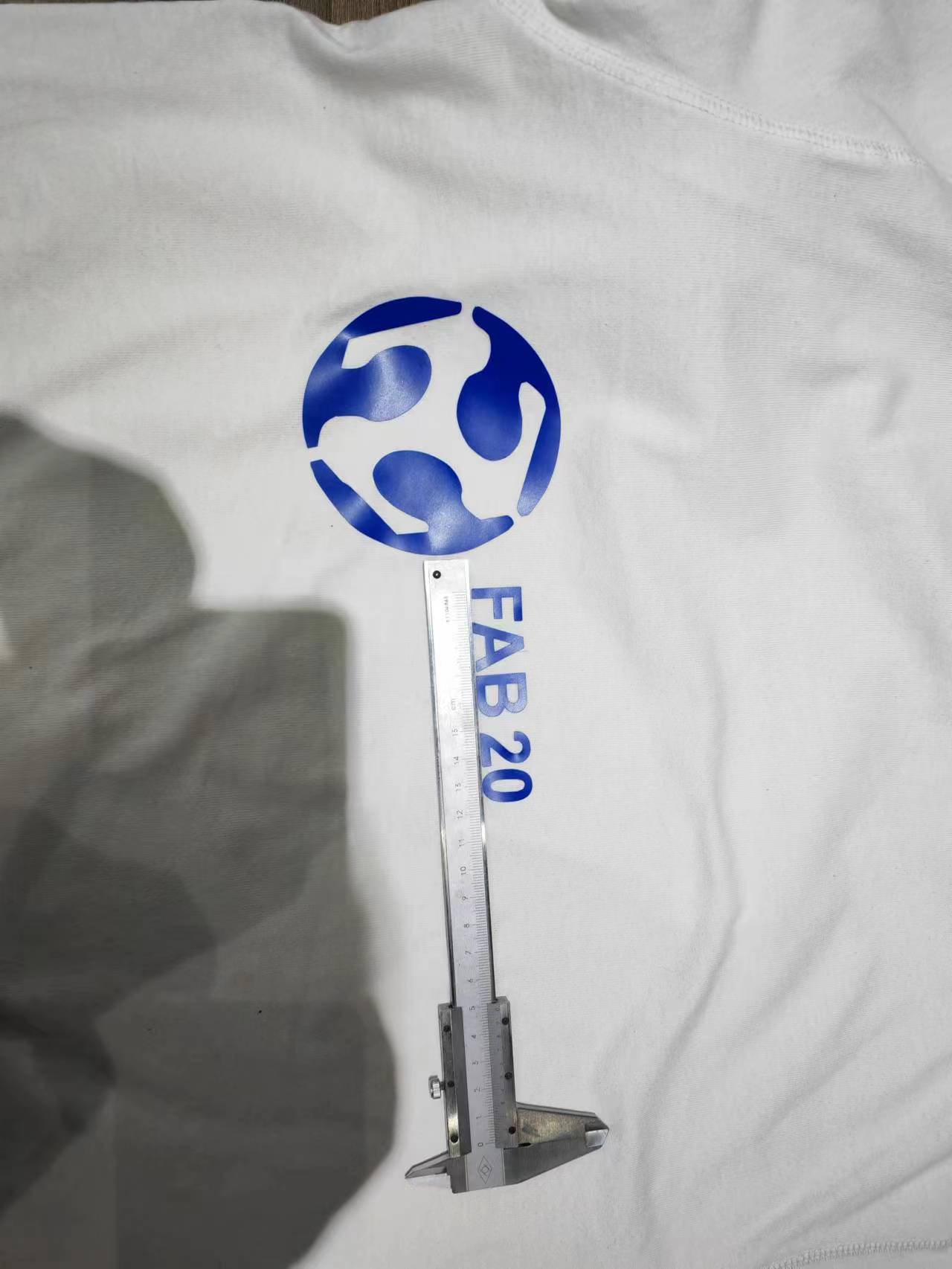
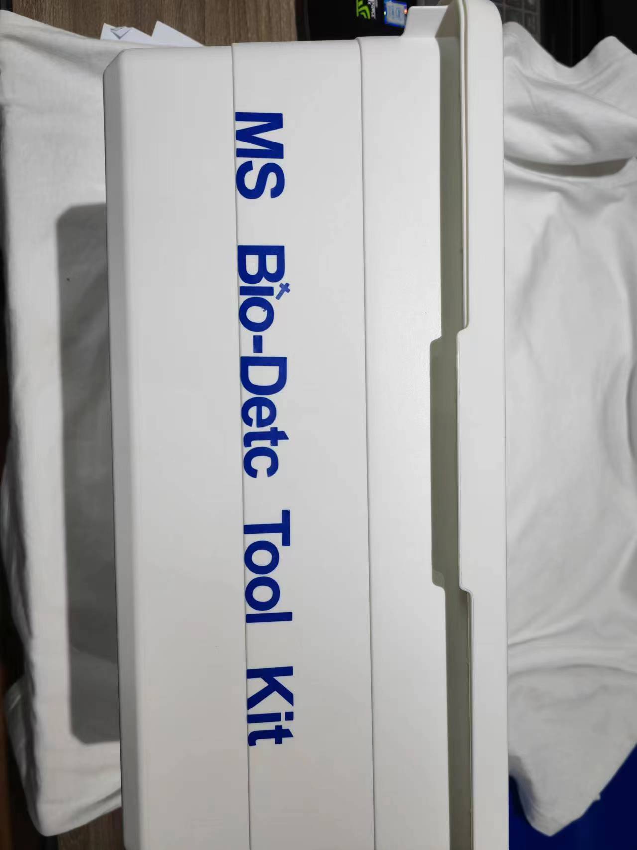
In this week's practice, I have first characterize my laser cutter's parameters and then design, laser-cut, and document my Dog-feeder-box. Besides I have also cut some stickers for my T-shirt and tool box.
Result assembly of cut materials last week This assembled box was cut for my mid-term project 'Dog-feeder'.
Introducing Laser Cutting technology
Laser cutting technology uses a high-powered laser beam to cut, engrave, or mark materials with exceptional precision. The process involves focusing the laser onto the material, which melts, burns, or vaporizes the targeted area, resulting in a clean and accurate cut1. This technology is widely used in industries such as automotive, aerospace, electronics, and more due to its precision, efficiency, and versatility.
Group Work 2023 - Safety Precautions for Using Laser Cutting Technology
When using laser cutting technology, it's crucial to follow these safety precautions to prevent accidents and injuries:
- Proper Training: Ensure you are properly trained on the laser cutter's operation and safety procedures.
- Wear Safety Gear: Always wear laser safety glasses, a mask or respirator, and thick gloves to protect your eyes, lungs, and skin.
- Follow Manufacturer's Instructions: Adhere to the manufacturer's guidelines and safety instructions for your specific laser cutter.
- Use Safety Interlocks: Never bypass or disable the safety interlocks built into the laser cutter. These interlocks are designed to prevent accidental exposure to the laser beam.
- Ventilation: Ensure proper ventilation to avoid inhaling harmful fumes produced during cutting.
- Fire Safety: Keep a fire extinguisher nearby and be aware of the fire risks, especially when cutting flammable materials.
- Supervise the Machine: Never leave the laser cutter unattended while it's in operation.
- Keep the Area Clean: Remove any debris or flammable materials from the cutting area to prevent accidents.
- Logbook: Maintain a logbook detailing who used the laser cutter, the cutting time, and the materials cut.
- Stay Alert: Always stay focused and alert while operating the laser cutter.
By following these precautions, we can safely harness the power of laser cutting technology for our projects.
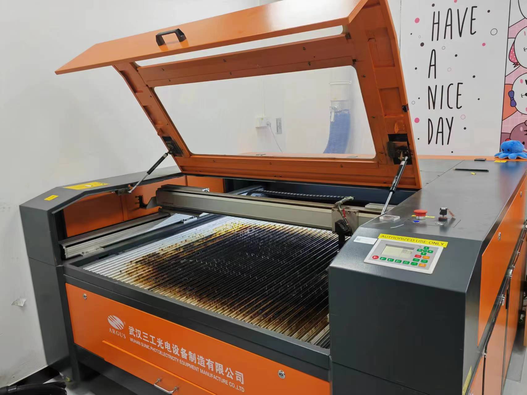
Group Work 2023 - Laser Cutting Test Practice
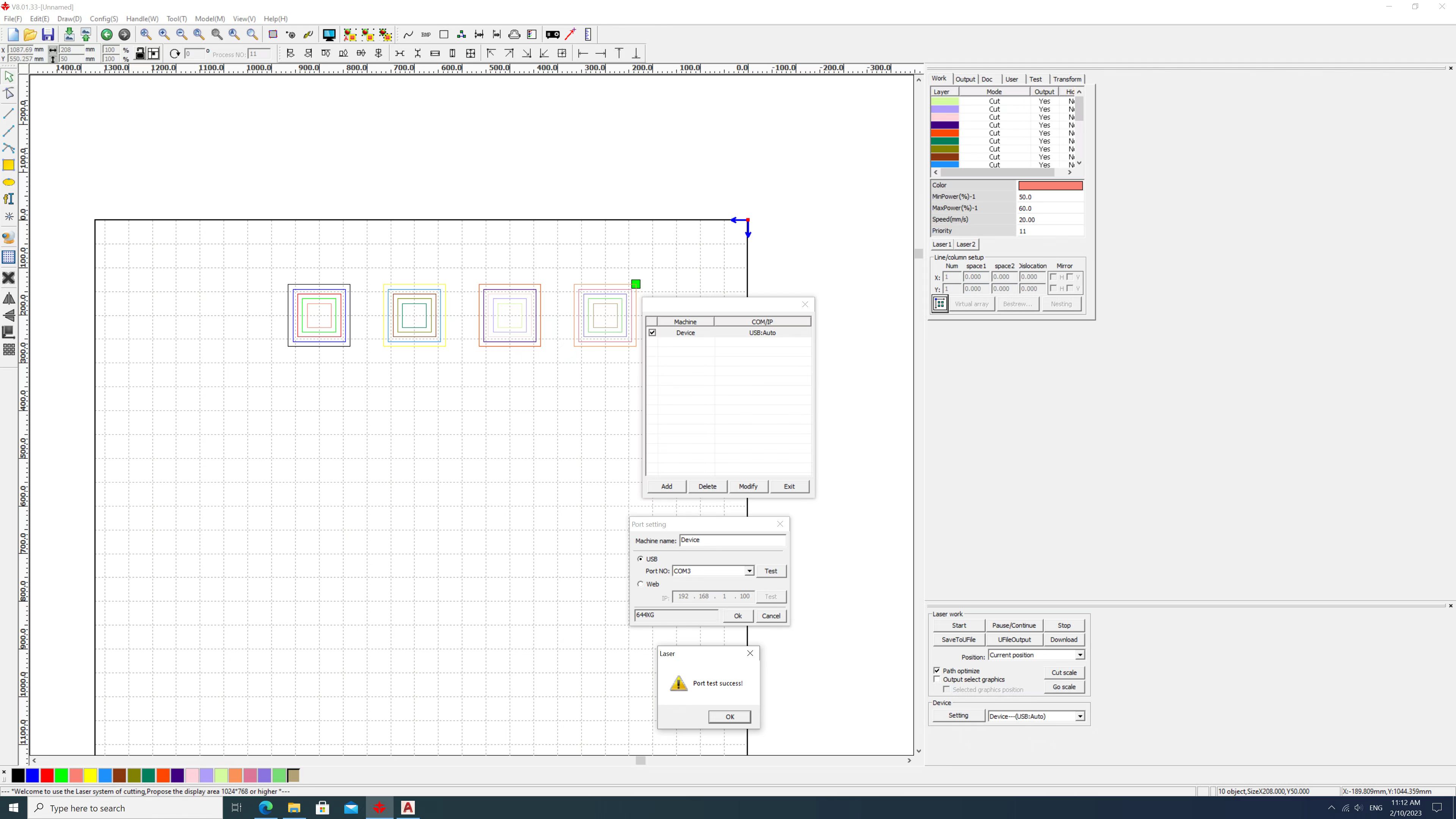
The laser cutter we used this week is ARGUS made by Wuhan Sunic Photoelectricity Equipment Manufacture Co.Ltd with 80W of output laser power. The detail can be seen here.
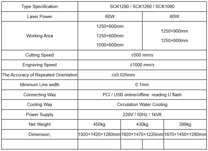
The technical parameters are documented as below.
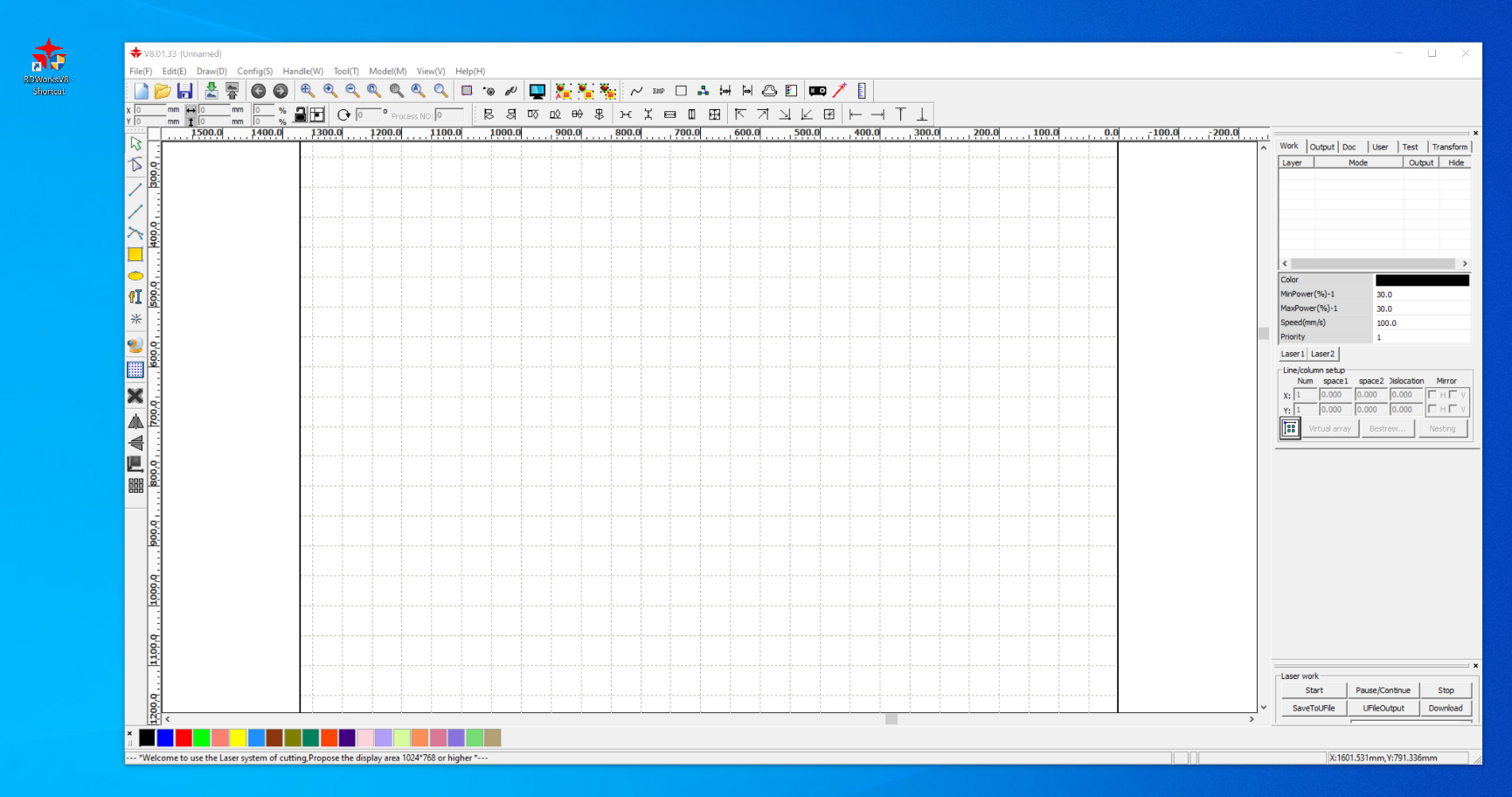
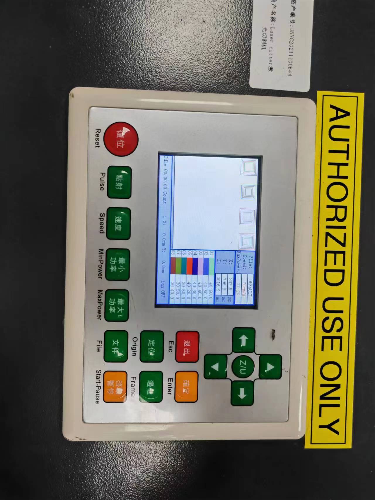
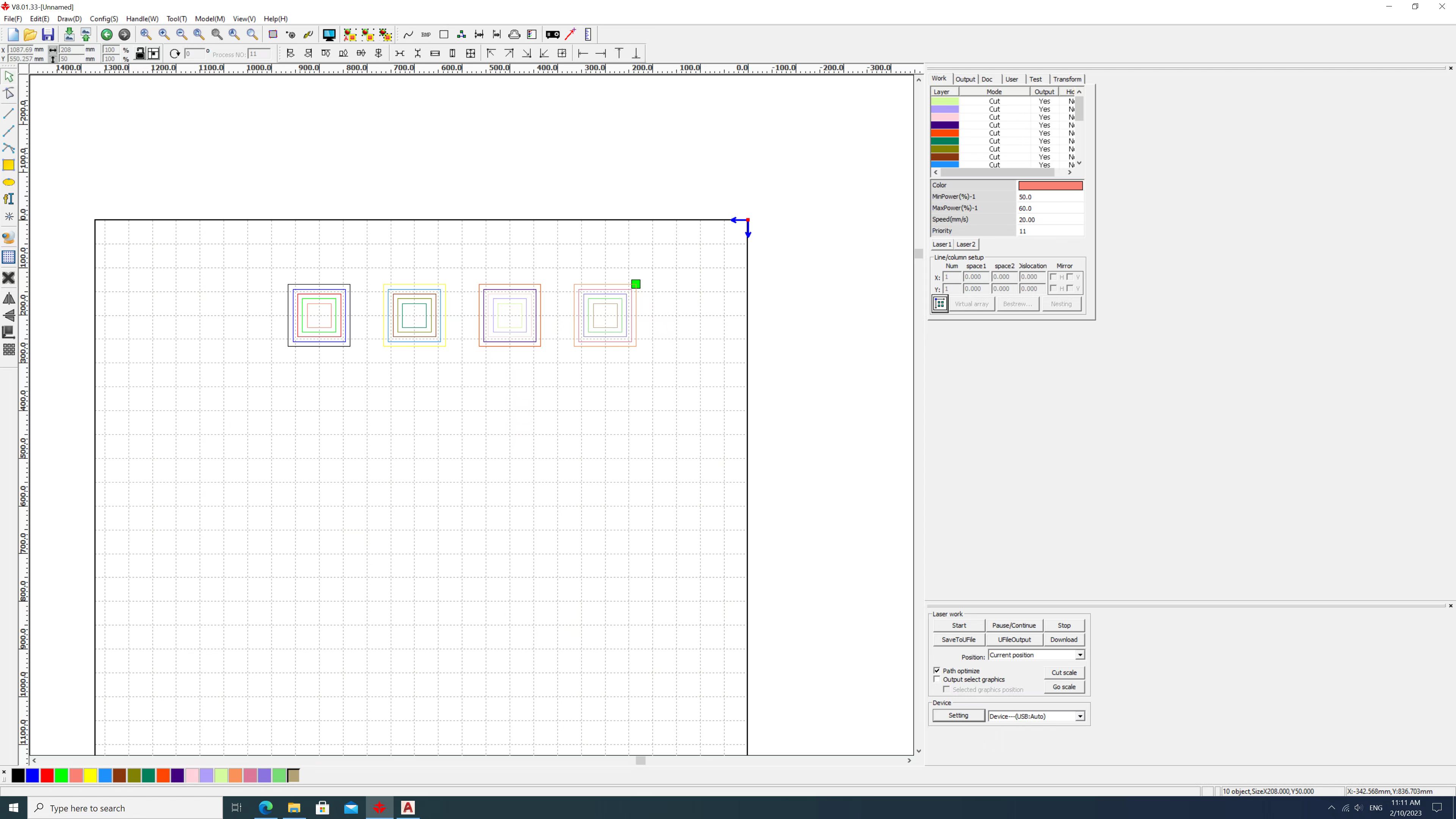
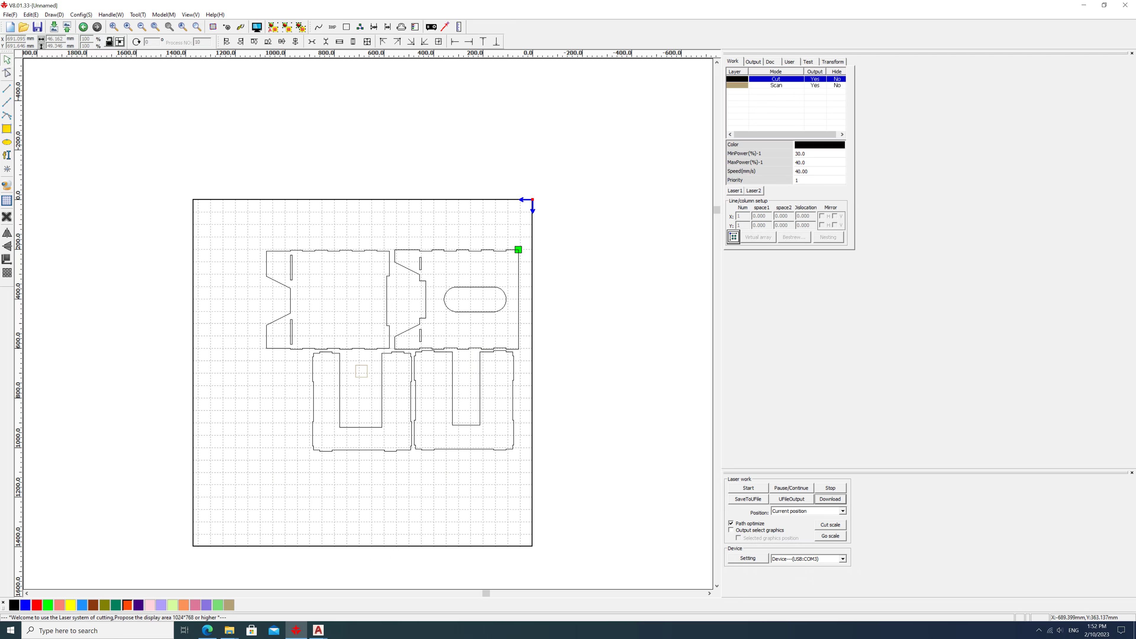
The laser cutter software is RDWorksV8. The cutter may read AI\BMP\GIF\JPEG\PCX\TGA \CDR\DWG\TIFF\PLT\DXF files.
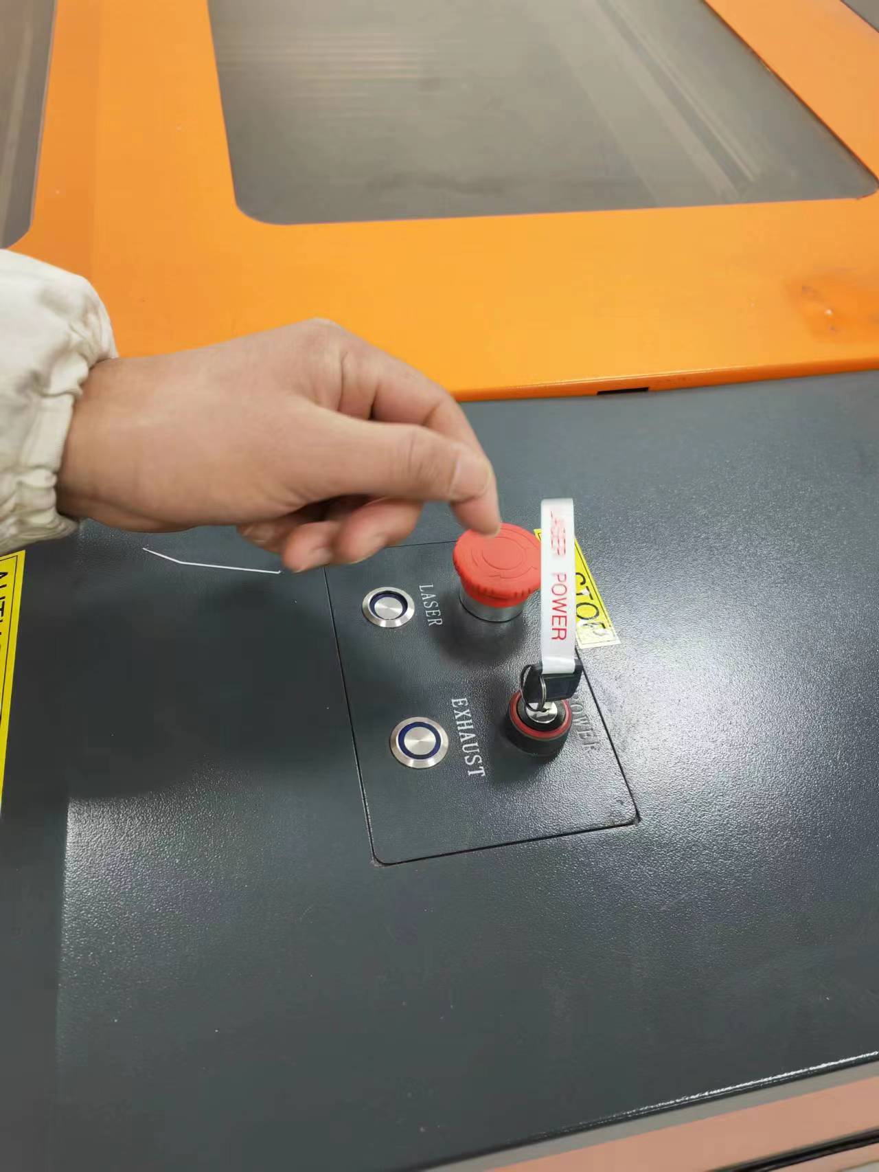
The power of laser beam and air exhaust are separately controlled by these two buttons.
The configration setting of the machine and the plane movement of the laser head is controlled using a pannel.
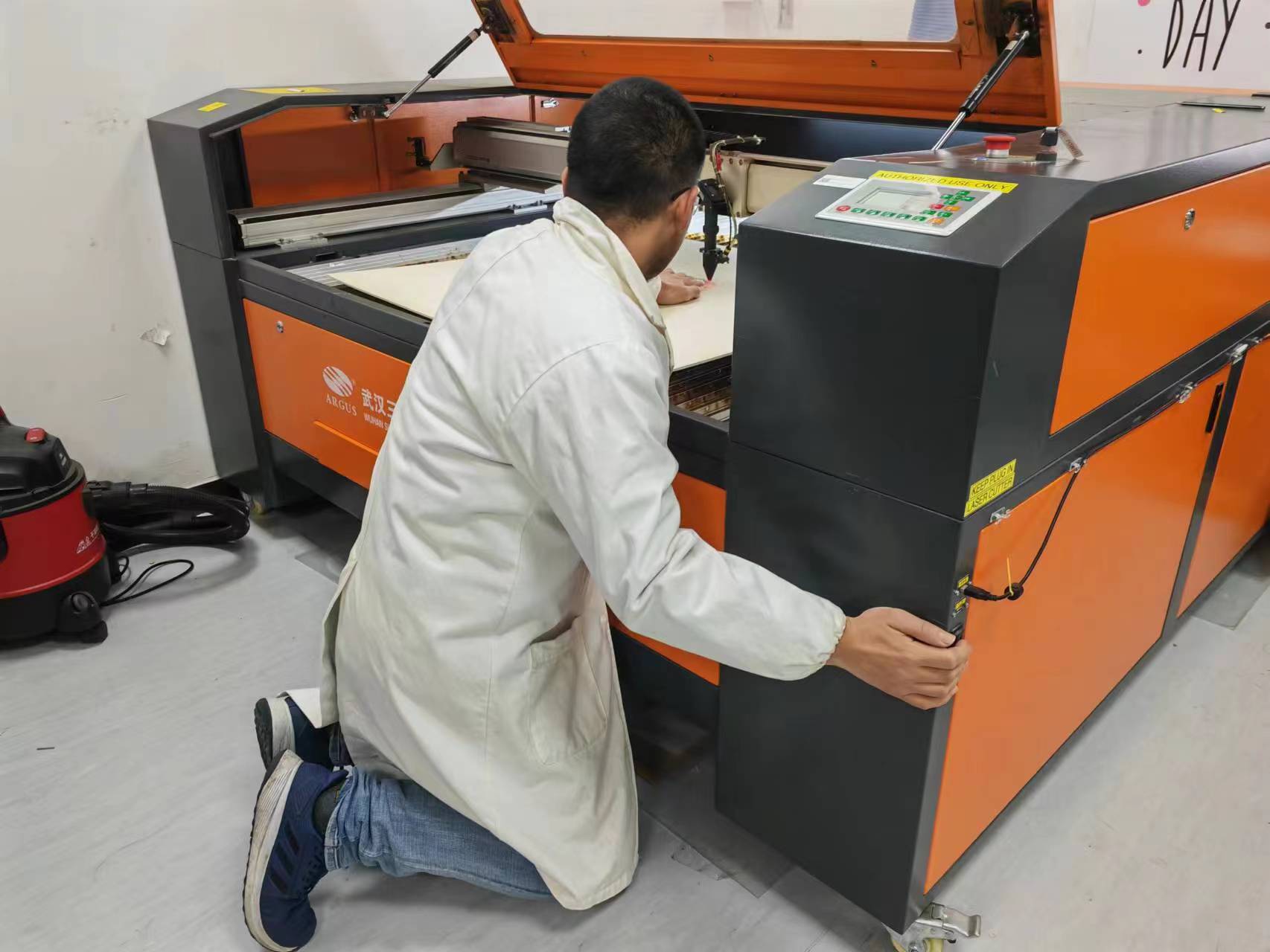
The vertical movement of cutting bed is controlled with a button on the frame. The focus was tested at this stage which is approximately 4.8mm.
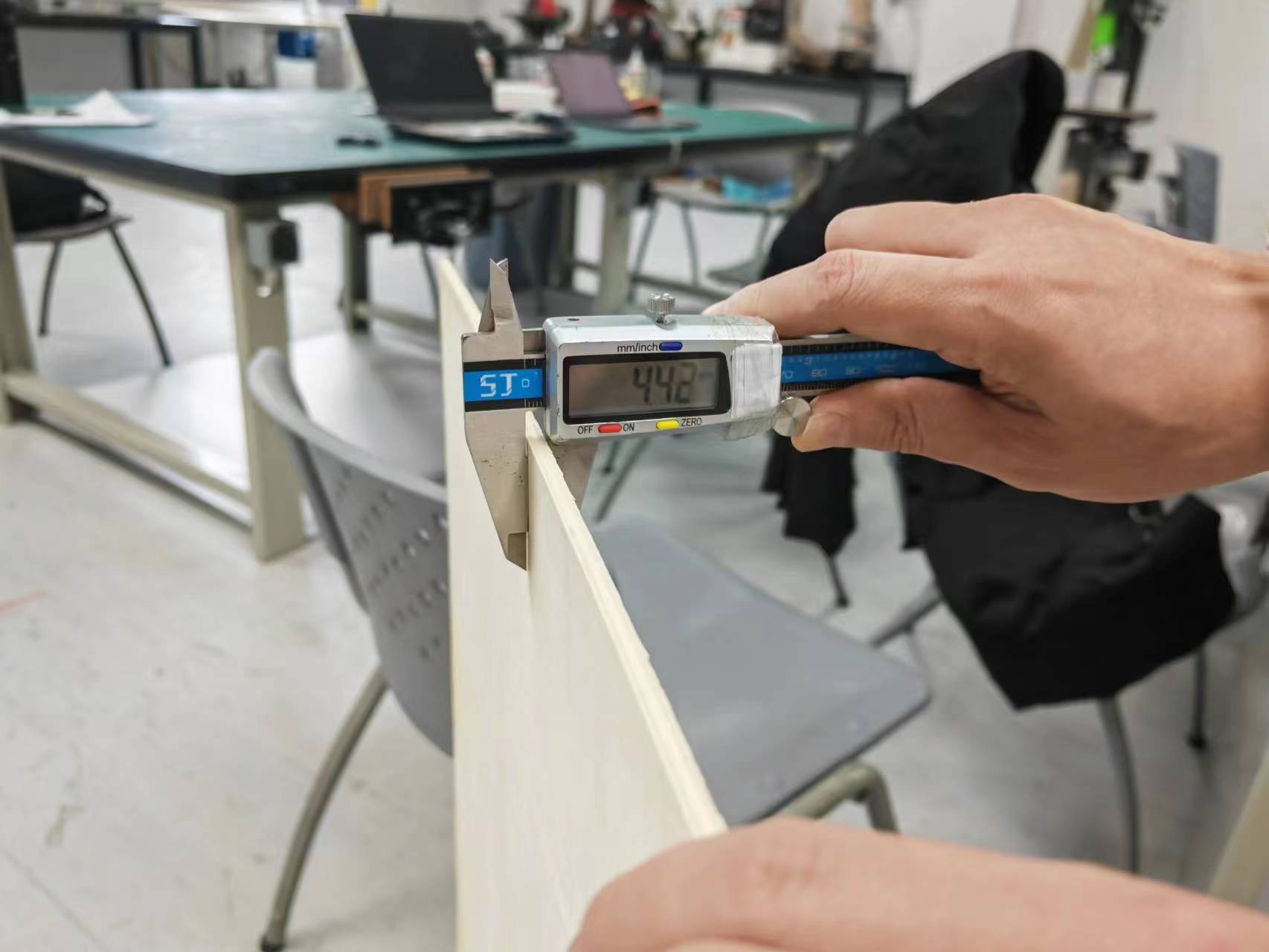
The material used for cutting exercise is wood boards with 4.42mm thickness.
Test cutting
In this part we design a demo graph which can check the cutting result of 2 most important variable parameter of the cutter (power and speed).
The cutting power applied are 20%, 30%, 40%, 50%, 60%.
The cutting speed applied are 20mm/s, 30mm/s, 40mm/s, 50mm/s.
The line color on the graph were change to meet the laser cutter software's requirement. Different line color represent different cutting power and speed.
Then download to machine and process.
We get the following result.
(Where Y represent successful cutting, N represent unsuccessful cutting)
| Power\Speed | 20mm/s | 30mm/s | 40mm/s | 50mm/s |
|---|---|---|---|---|
| 20% | Y | N | N | N |
| 30% | Y | Y | N | N |
| 40% | Y | Y | Y | N |
| 50% | Y | Y | Y | Y |
| 60% | Y | Y | Y | Y |
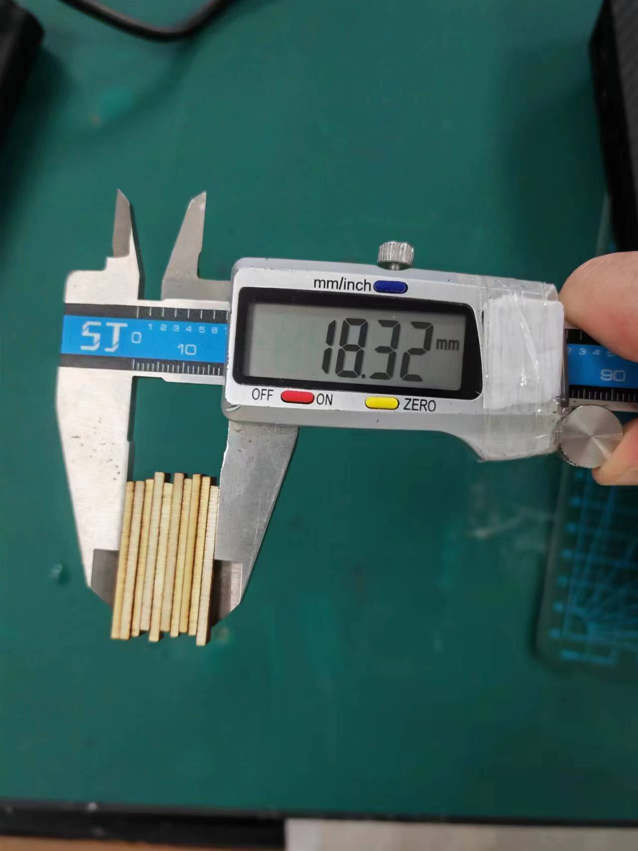
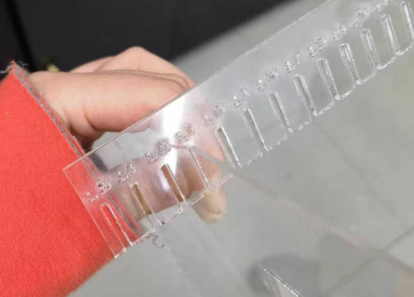
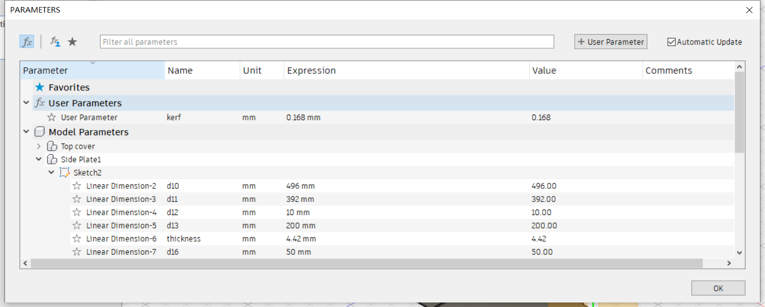
Besides we have tested the kerf (the diameter of laser). We cut 10 rectangle pieces for measuring the kerf and the designed width of each rectangle is 2mm. The diameter of the laser beam can be calculated as kerf=(20-18.32)/10=0.168mm.
The joint clearance test was done using 2mm thick acrylic board and the best joint clearance is 1.4mm.
Test machine characteristics
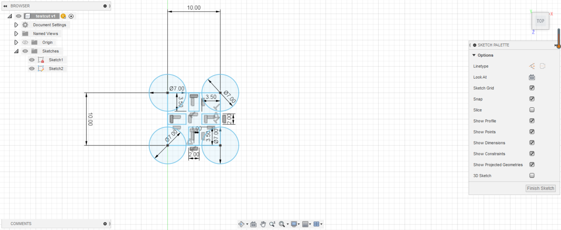
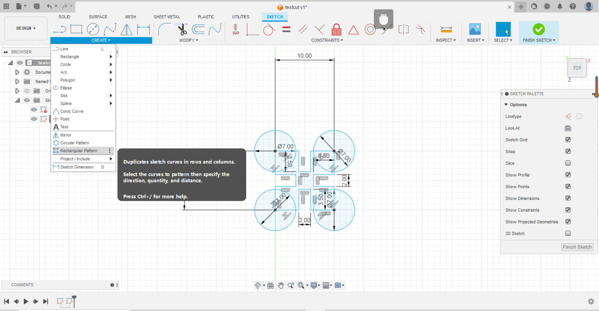
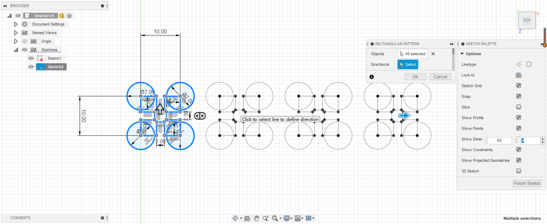
Before final cutting the kerf value was added as a parametric value into the previous Week2 design.
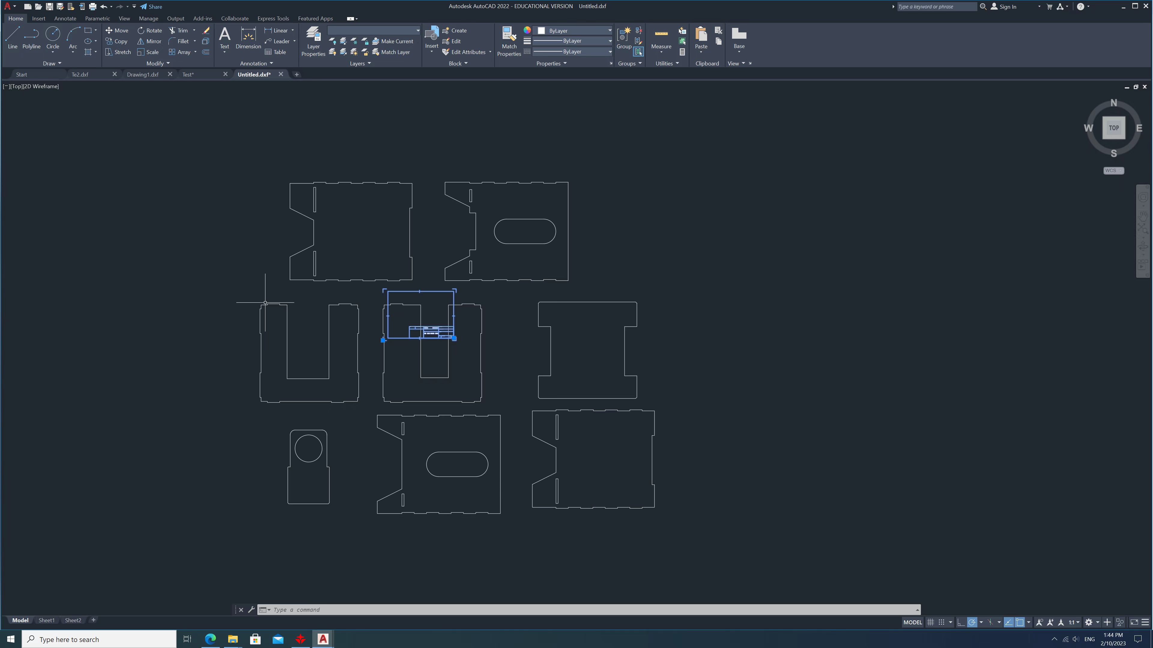
The 3D design in Week2 was convert to 2D drawings and load to the software.
In formal cutting process we use 40% power with 40mm/s speed.
The cut pieces are collected after exhaust air is completely removed.
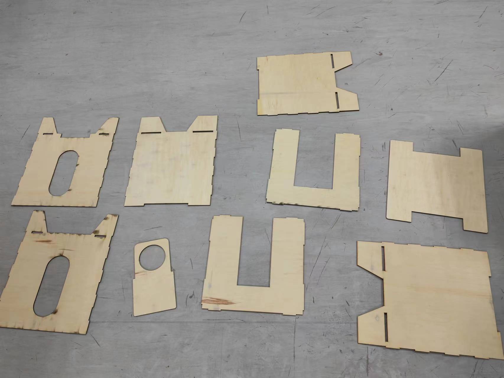
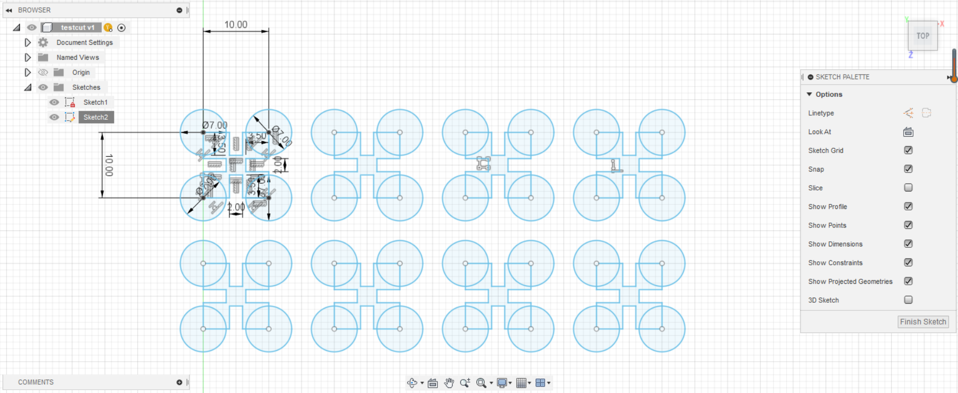
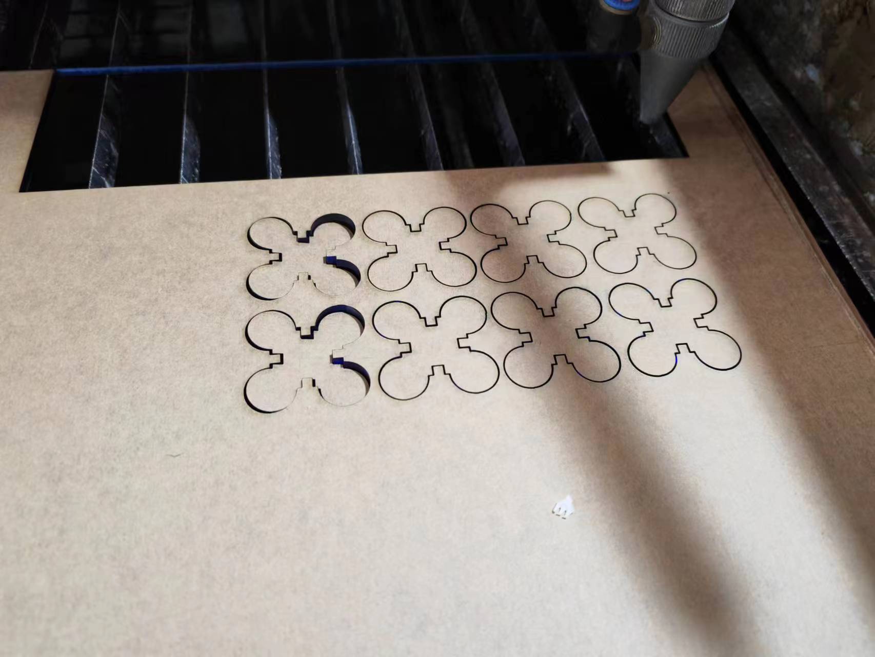
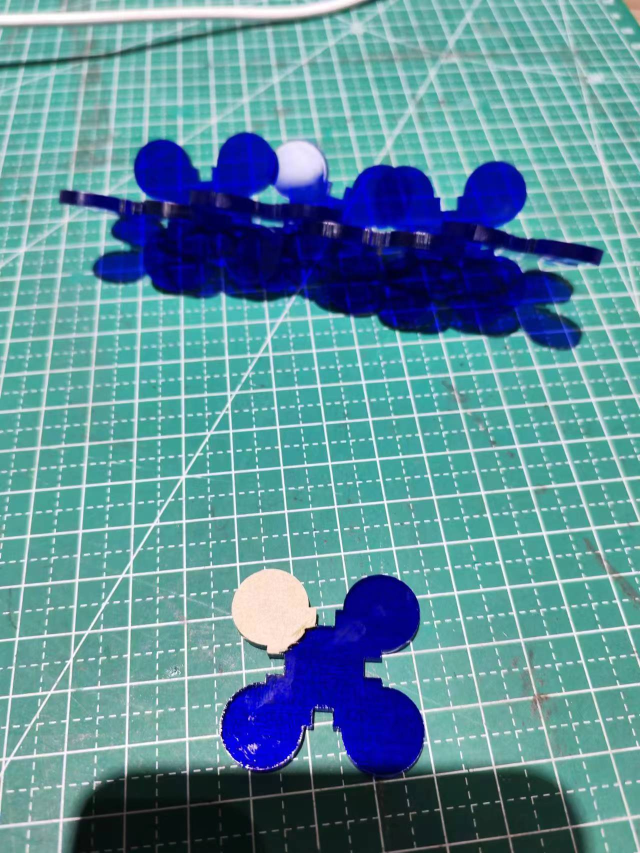
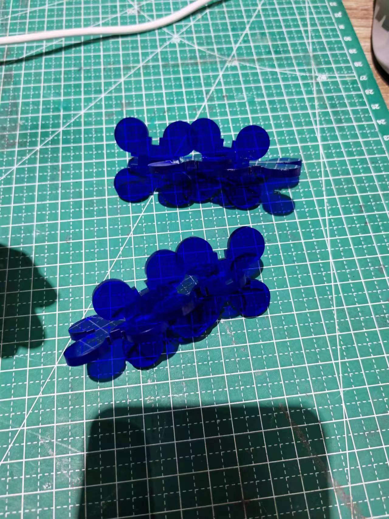
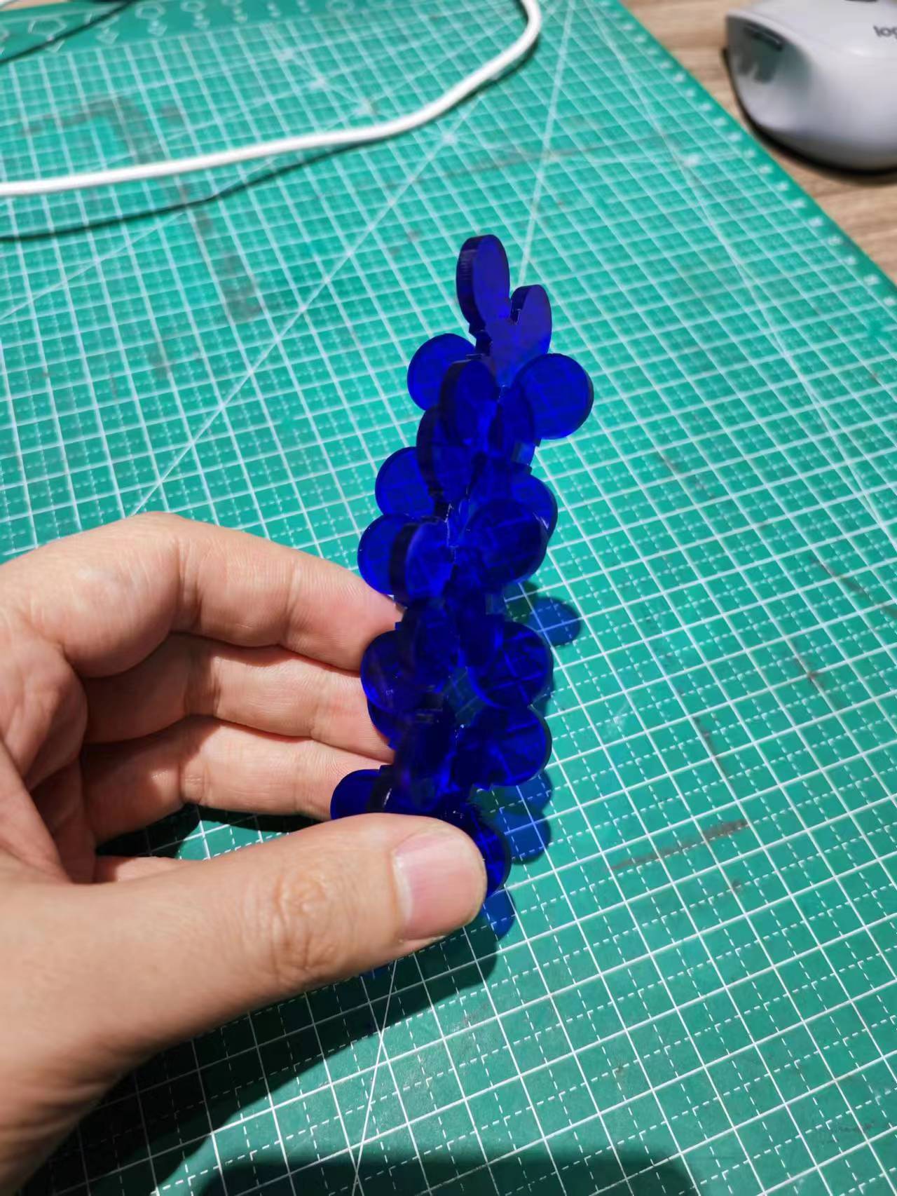
Individual Assignment - Design and cutting a construction kit
I have also designed a very simple construction kit and cut it with laser cutter. Firstly using Fusion360 to draw the 2D drawing of my construction kit.
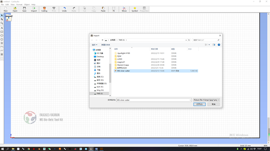
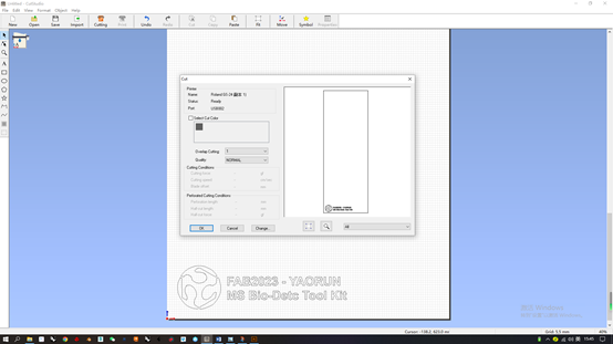
Vinyl Cutter Assignment
A vinyl cutter is a computer-controlled machine used to cut shapes and designs from vinyl sheets and other materials like paper, cardstock, and thin plastic sheets. It utilizes vector-based designs created in software such as Adobe Illustrator or specialized vinyl cutting software, allowing the computer to control the blade for precise cuts. Vinyl cutters are versatile, cutting not only vinyl but also fabric, magnetic sheets, and specialty papers. They are commonly used for making signs, banners, decals, and stencils, and are popular in crafting, scrapbooking, and apparel decoration. These machines are relatively easy to use, require little maintenance, and are cost-effective due to the inexpensive nature of bulk vinyl, making them ideal for a variety of projects.
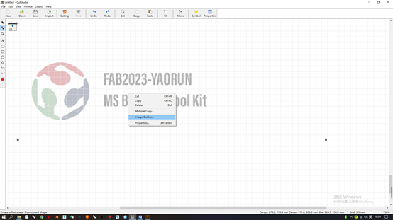
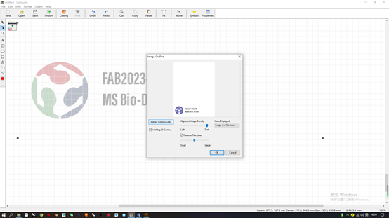
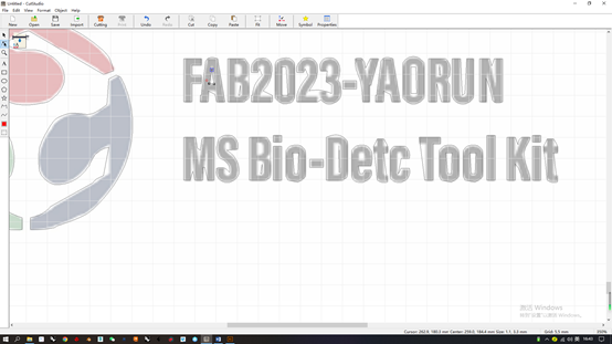
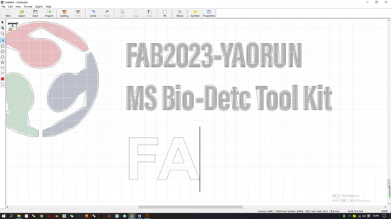
Prepare a 2D design for vinyl cutting. I have used Photoshop to make a logo design for vinyl cutting.

Reference
All original design files in this week can be found at my repo (https://gitlab.fabcloud.org/academany/fabacademy/2023/labs/ningbo/students/yaorun-zhang/-/tree/main/docs/assignments/week3/design-file).