
3D_Scanning_and_Printing
| Week | 5 |
|---|---|
| Assessment Guide | http://fabacademy.org/2023/nueval/3d_scanning_and_printing.html |
| Lecture Notes | Week 5 - 3D Printing and Scanning |
| Progress Estimate | 76% |
Student Objectives
Student Objectives
Assignments
Individual
- Design and 3D print an object (small, few cm3, limited by printer time) that could not be easily made subtractively
- “Your model has undercuts , overhangs, nested parts, meshes etc.”
- 3D scan an object (and optionally print it)
Group
- Test the design rules for your 3D printer(s)
- Document your work on the group work page and reflect on your individual page what you learned about characteristics of your printer(s)
Student Tasks
Student Tasks
- Linked to the group assignment page
- Explained what you learned from testing the 3D printers
- Documented how you designed and 3D printed your object and explained why it could not be easily made subtractively
- Documented how you scanned an object
- Included your original design files for 3D printing
- Included your hero shots
If at first you don’t succeed, fail; fail again.
Pre-work, or crystal ball Parallel Design
I own a UNIZ Ibee (a 4K monochrome MSLA resin printer), and an Anycubic Wash And Cure Plus station for, well washing and curing prints. These were initially bought to do some Small Businessy things. Life had other plans though, and those involved a lot of moving. Given the safety precautions required in working with resin, I wasn’t able to keep it set up consistently and printing regularly. This left me with probably a few hundred hours of research in the 3d printing space, and unfortunately limited printing time.
In terms of 3D scanning, I’ve previously played with photogrammetry in Sony’s lovely Sony 3D Creator app
In The Weeds
To start off this week, I went about getting myself authorized to use the resin printer in the space, a FormLabs Form 2, and a quic rundown on using the space’s FDM printer, the Prusa i3 MK3S with MMU2S. My notes from that are below
Authorization process Notes:
Resin Printer
- Form Labs Form 2
- Pre form is the slicer from FormLabs
- 2 manual wash basina
- Used iso container
- 20 mins in the iso bath
- Cure station includes temperature settings, different per resin
- “Gray V4" is kinda the standard resin, economical and good results
- Can create account on form labs site, register printer to dashboard, can keep track of print, see live assessment of FEP quality
- If heat map looks pretty uniformly gray, time replace the FEP
- Resin Stock
- Gray V4
- “doesn't need to cure" lul
- Clear
- High temp (up to ~300c)
- Durable, polypropylene like
- Fragile until it's cured
- Let it cure on the supports
- Rough 2000
- Polyethylene-like, 2000 corresponds to rating, very stiff
- Basically any FormLabs resin cartridge can be used, can make a formal case for stocking it in the lab
- Tray has to match the resin.
- Gray V4
- the overhead Red light’s for lighting workspace without UV curing resin
- more relevant for the previous printer
- Press and hold pwr button at the end to Hybernate machine, preserve LCD
- Stick around for first part of print, sometimes spits out Resin Quantity warning and won't print until checked
- Tank will be keyed to the first resin used with it, is blank until then
- Max build: ~5.9”³
FDM Printer
- Prusa i3 MK3S with MMU2S
- Prusa slicer should have presets
- Different bed for PLA (green “Smooth2") vs everything else (" textured”)
- Put it on SD card, select Print from SD
- Will warn when runs out of filament
- Crash protection, will stop if blowing
- Have to tell it which filament
- Heats up to temperature
- .04 mm nozzle
- Dan Williams: “For stuff near a hotend or any other heat source: it is also a good idea to print in white or another light color if possible. Black materials absorb dramatically more radiated thermal energy than white and even with temperature resistant materials: less heat is better heat and people too often overlook the thermal implications of color choice.”Prusa Knowledge BaseAll information you need to know about Original Prusa 3D printers. Assembly manuals, print quality troubleshooting, calibration, PrusaSlicer…
 https://help.prusa3d.com/en/
3D Scanner
3D Scanner - Afinia ES360 - i3Detroithttps://www.i3detroit.org/wiki/3D_Scanner_-_Afinia_ES360
Afinia ES360 Desktop 3D ScannerThe Afinia ES360 Desktop 3D Scanner delivers high-accuracy 3D scanning faster than ever before, using safe, white light scanning. http://afinia.com/3d-scanners/es360-desktop-3d-scanner/
- Basically, extremely finicky and no one has suceeded in getting much better than a barely workable scan. Very not endorsed.
Building a Model
To build a 3d model, I really puzzled for a bit about what the given parameters would look like. Creative Design has not been my strong suit this year, unless we’re talking Interior Design (in which case, ask me about how I’m turning a hallway into a pantry!).
After consulting my advisor to make sure it wouldn’t be following-the-letter but flouting the spirit of the assignment, I decided on the classic “sphere inside a cube skeleton.” If this goes well, I’m considering going a little farther out the spiral and seeing if I can replace the sphere I CAD’ed with a spheric lithophane generated online. It’s around my wife’s birthday, and I’d love to give her a nifty photo tealight rather than just give the planet more waste-plastic. Plus Adrián showed us all his sphere in a cage during global open time so now I feel like have to differentiate a little. Thanks Adrián.
The Process
- So I started with a sketch of a circle, since my last tutor in Fusion said he usually starts with sketches. I chose to use the
Center Diameter Circletool to make a circle that was 25 mm.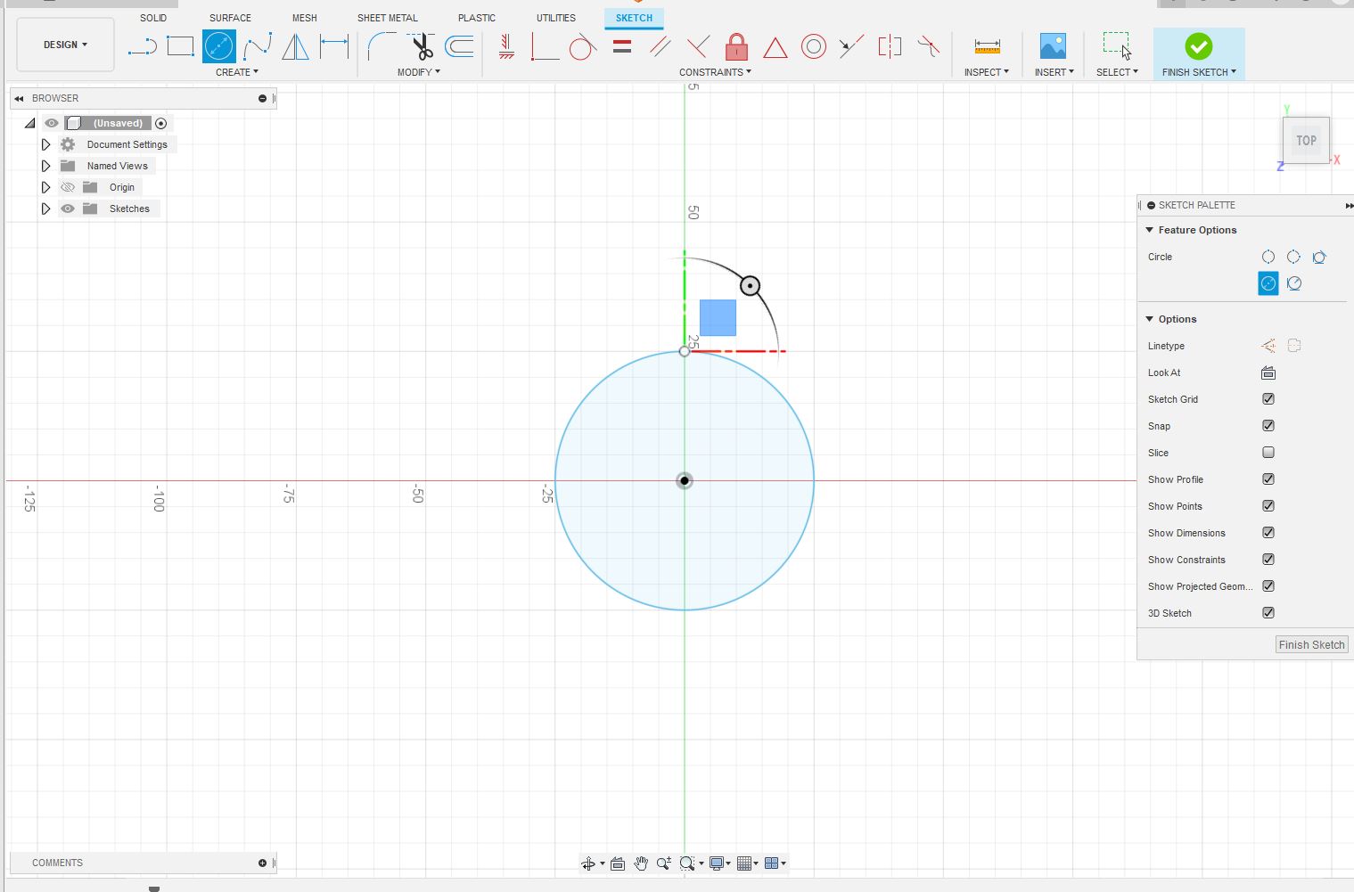
All circle, no crops
- I tried to use the
Revolvefunction to turn that into a sphere, but Fusion crashed in the process. This gave me a second to reflect on whether there was a better way to start.- I ended up going to the
Surfacemenu, mostly because I forgot I had clicked there, and thenCreate Form → Sphere. I chose to go 25mm this time too, but now it was becaue I looked at my notes from Global Open Time first, and saw Rico had recommended making a small part, about 30mm cubed in dimensions. I figure factoring in the outer cube shell, this should end up around that.
- I worried that the size may cause trouble if I decide to replace the sphere with a tealight-sized spheric lithophane later, but then remembered I can edit the dims at that time in the history/timeline
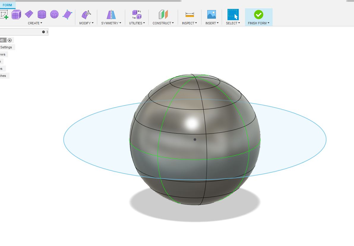
almost like a planet - I ended up going to the
- Next was getting started on making the cube around it. I decided the best approach would to be to use
Create Formagain and make a cube from there, but this time from theSolidmenu and hollowing it out after so I wouldn’t have to worry about adding thickness for the legs.- This turned out to be a mistake, as I missed the Z dim and instead ended up with a weird hat for my sphere. This is more the territory of “Something you could make subtractively, but just wouldn’t want to.” Which was close the assignment, but definitely not it.
- I then ran into trouble figuring out how to edit the dimensions. Hope this isn’t a poor omen for my ability to edit the dims later like I mentioned in 2b
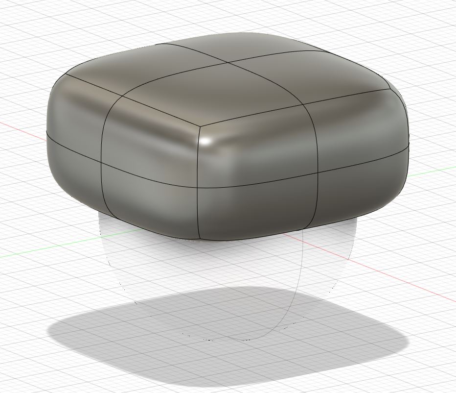
Some sort of weird hat or terrible to use ottoman
- After deleting my weird couch cushion, I decided to sketch a square, and then go the extrusion route.
- I used
Rectangle From Centerand went with dims of 30x30, and a center point of Origin, the same as the centerpoint of the sphere
- I feel like, if I’m reading the tool tips in Fusion correctly, the issue last time was that Forms don’t have Design history, so editing it after the fact wasn’t as easily done. Hopefully starting from a sketch solves this.
- I used
- Extruding seemed straightforward, but I quickly realized I need to be clear on a couple steps. I selected from the
Solid Menu, still hoping to hollow out later- Direction had to be set to
Symmetricor2 Sides, or else it started halway up the sphere instead of centered
- Distance needed to be cut to 15mm to account for it extruding symmetrically in both directions. The other option was to swtich
MeasurementtoFull Lengthand keep 30mm.
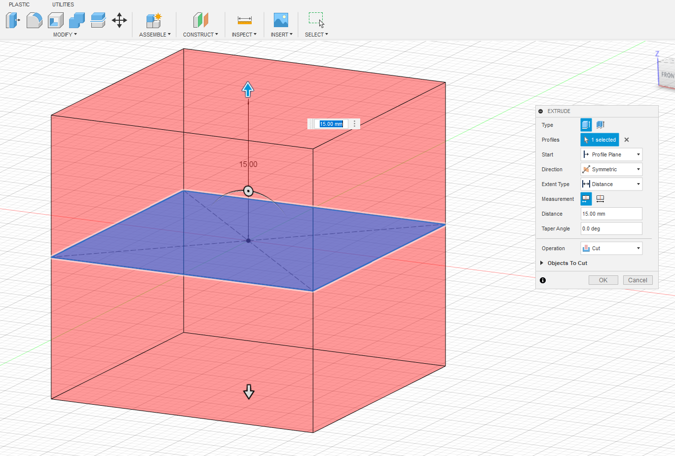
- Direction had to be set to
- At this point I hit backspace to edit some field and instead accidently finished editing the extrusion, so I went back in timeline to edit the properties and discovered some more options to get me futher towards my goal
Thin Extrudeseems to give me the option of a hollow shell like extrusion without inner area. After some hemming and hawing I’m setting the wall thickness to 3.5 mm to allow enough overlap with the sphere to cage it without going too crazy on materials. Also to hopefully allow to have tolerance broad enough for any inaccuracies in the print.
- It was at this point I realized I could set the
Taper Angleto -20 degree to enclose the sphere enough to fulfill the assignment. Could be Mission Accomplished, and I’ll come back to this if I need to deliver at the end of the week, but I want to push myself a little farther to get my original design vision. Nice to have a safety net though.
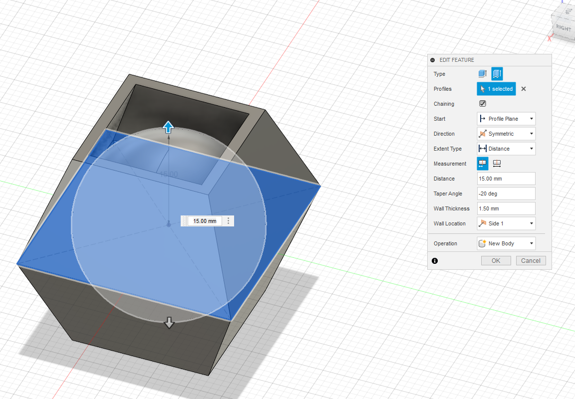
Pretty sure you can’t CNC that lazy Tie Fighter
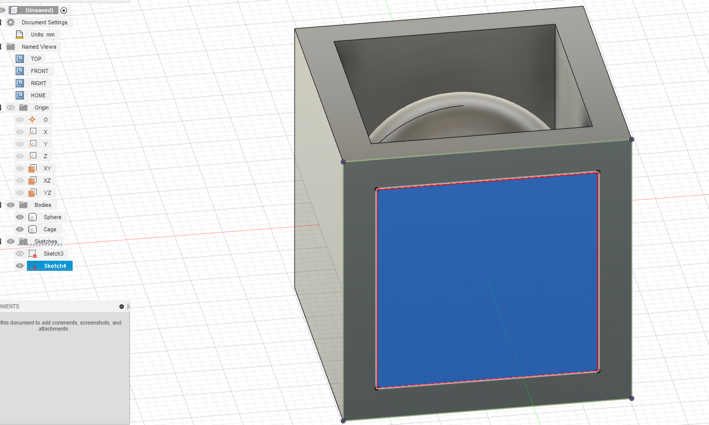
- I set the
Taper Angleback to zero and started work on cutting out the sides of the cube- I started by tracing the inner wall shape on the top, where it’s cutout, and cut & pasting that sketch to the face of another wall. I have no idea what I’m doing here and just experimenting on a hunch.
- I’m realizing that the feature I’m looking for is burried under
Extrude. So I selectedPush/Pullon the sketch, and than set theDistanceto the thickness of the walls, -3.5 mm (negative to make it go in the correct direction), and went withCutas theOperation. It was pre-selected, so Fusion has some idea of what I’m trying to do, but I still looked through the tooltips for all the items underOperationso I’ll know for next time.
- I ran into a minor issue of not knowing to unselect the severe under
Objects To Cut, but caught it before too much headache
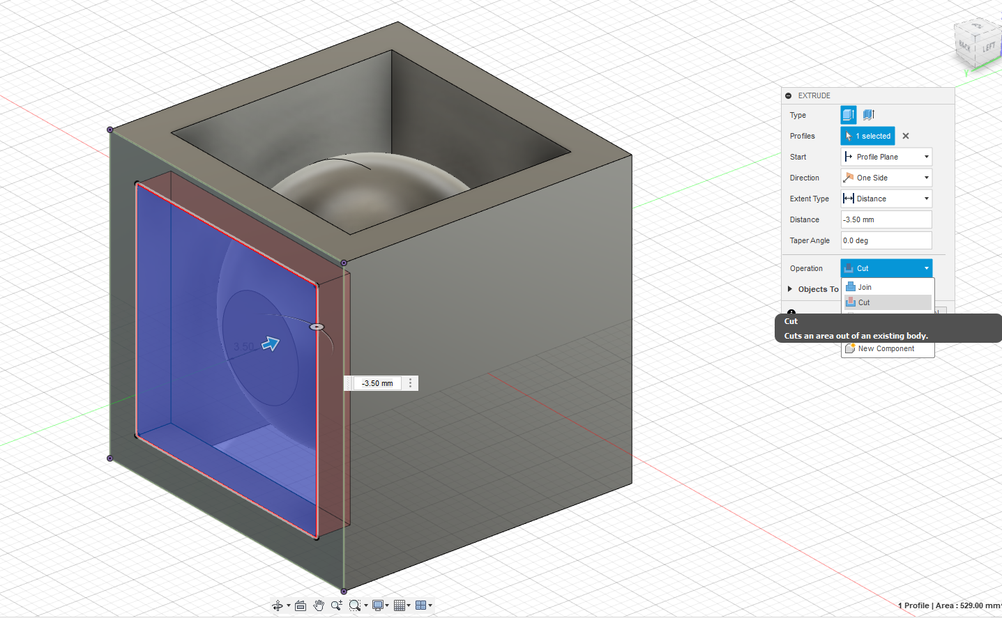
Sharp tooltips save lives
- In trying to figure out how to reproduce the
Extrude/Cut, I realized I should edit the dimensions on the original to the full width of the cube instead of the width of one wall, that way it would do two sides at once.- For the life of me, I can’t figure out how to copy my
Sketch+Cutactions onto another face. I spend more time on this than I should. After googling, Autodesk tells me I couldn’t paste the sketch because I wasn’t in sketch mode. For repeating theCutitself, innovatenate on the Autodesk forums explains I needed to use thePatternorMirrortools, but in the future I should probably use theHoletool
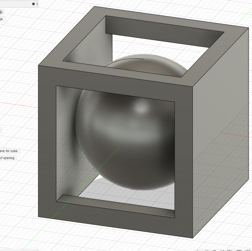
- For the life of me, I can’t figure out how to copy my
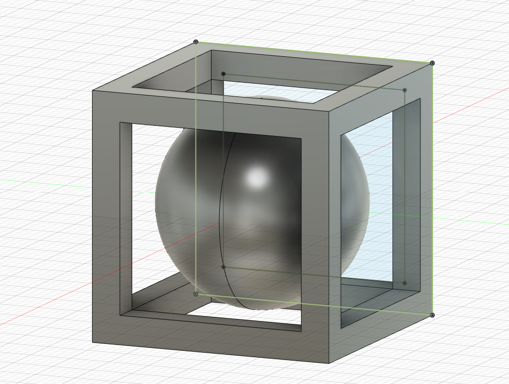
- After multiple tries of different features with no progress (not sure how
MirrororPatternwork yet apparently), I gave up and repeated what I did in step Step 7 A and B.- It looks like I’m going to need to make the sphere bigger now though, to save myself headache during the print. As set currently, it just floats there, which may be challenging to recreate on a buildplate for FDM or resin.
- At this point I loaded everything up in the slicer and realized I need to make some changes to deal with the print time. I first
Shellthe sphere to hopefully use less plastic and print time. After discovering it adds more (detailed later) I come back for vengance. This sphere’s getting beheaded! Which is to say I decide that if it’s going to take this much time and material, I’m gonna chop the top off so it can be a pencil holder or the like.- I start by setting an
Offset Planefrom theConstructionmenu. After futzing with the numbers a little I decide on 12 mm by eyeballing it. Since it’s offset from origin my distance values have to be a bit less than half the diameter of the sphere. I’m doing this with the goal of setting up a plane so I can use one of the “Split…” functions in the Modify menu, to later seperate the piece and then useModify → Removeto get rid of the upper portion but maintain it in the timeline.
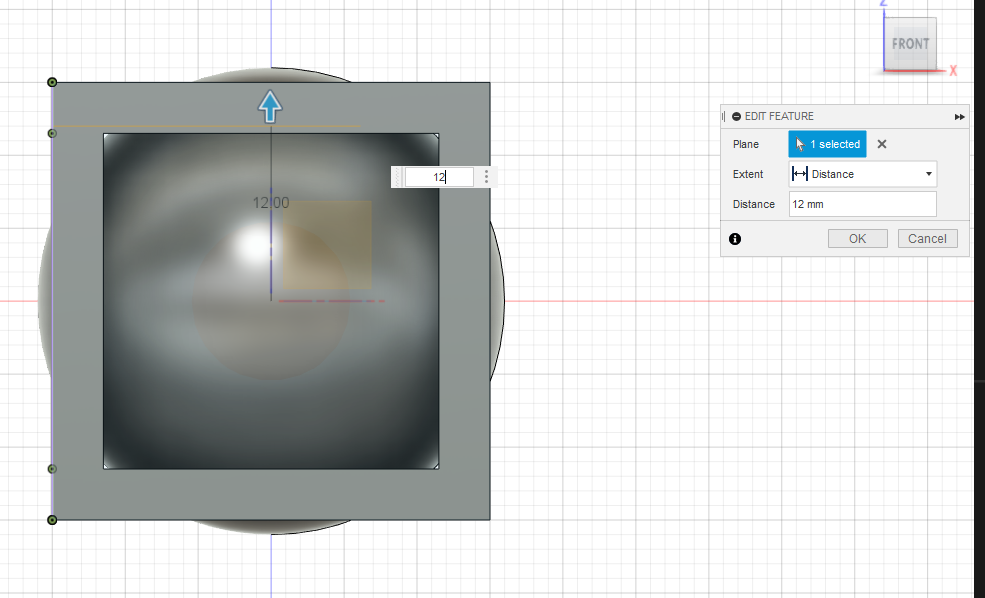
- I start by setting an
- The
Split Bodytool underModifydoes what I’m looking for, seperating the top into a seperate body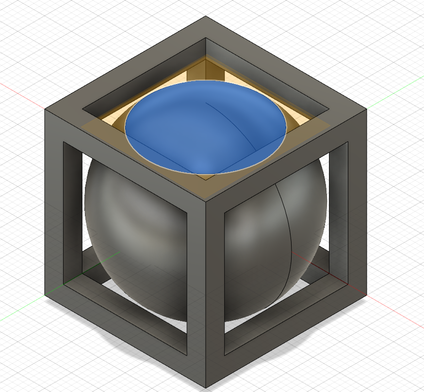
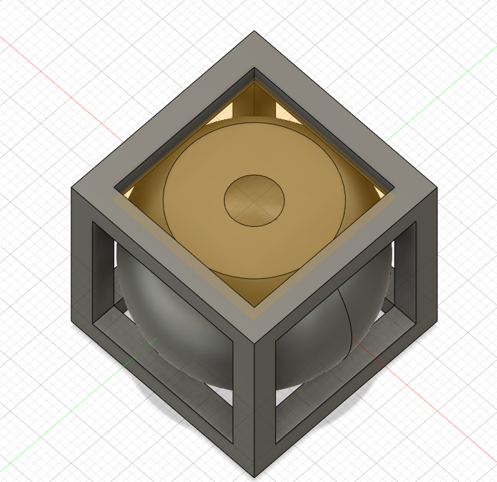
- But doing so helps me see exactly how proportionally thick I ended up making the shell of the sphere earlier. Wish I knew how to get an xray style view in Fusion like I get in a slicer. It would definitely help there be less back and forth between programs.
- I get the idea to try and hollow it out using
Push/Pull, seeing if the internal faces are accessible now I’ve chopped the top. Although I once again run into the issue where Backspace seems to somehow work as Enter and it just completes the operation instead of cancelling. Thankfully I’m able to use the timeline to easily modify this, without any googling.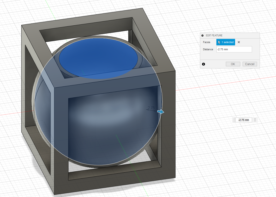
 https://www.autodesk.com/products/fusion-360/blog/master-the-timeline-browser-preferences/
Let’s get Printing!
My model finally done, I’m ready to move onto using the printer itself. I’m not acquainted with the models we have in the makerspace, and have not printed in FDM at all prior to this, so expecting a bit of learning curve on it.
The Slicer
Our printer is a Prusa i3 MK3S with the “Multi Material Unit 2S” add-on. I’ve seen multiple recommendations online recently for Prusa’s slicer owing to its new “organic supports” feature being rolled out, and have been told by others in the makerspace that it has well-tuned default profiles for its own models. So Prusa Slicer it is!
To get started I did a quick websearch for Prusa Slicer, and went directly to the relases page on the project’s github. After some reading up release notes I decided to go with the latest Public Alpha release, as
A) it had two previous alpha releases so hopefully had some kinks worked out and
B) the much discussed Organic Supports, as well as several other features are only in the Alpha release currently.
After downloading, I extracted the files and opened the .exe file in the directory. Since this was an alpha release it was intended to be able to be run on your machine alongside your already installed Stable Release, so it didnt’ include an installation wizard or the like. Just a straight up .zip.
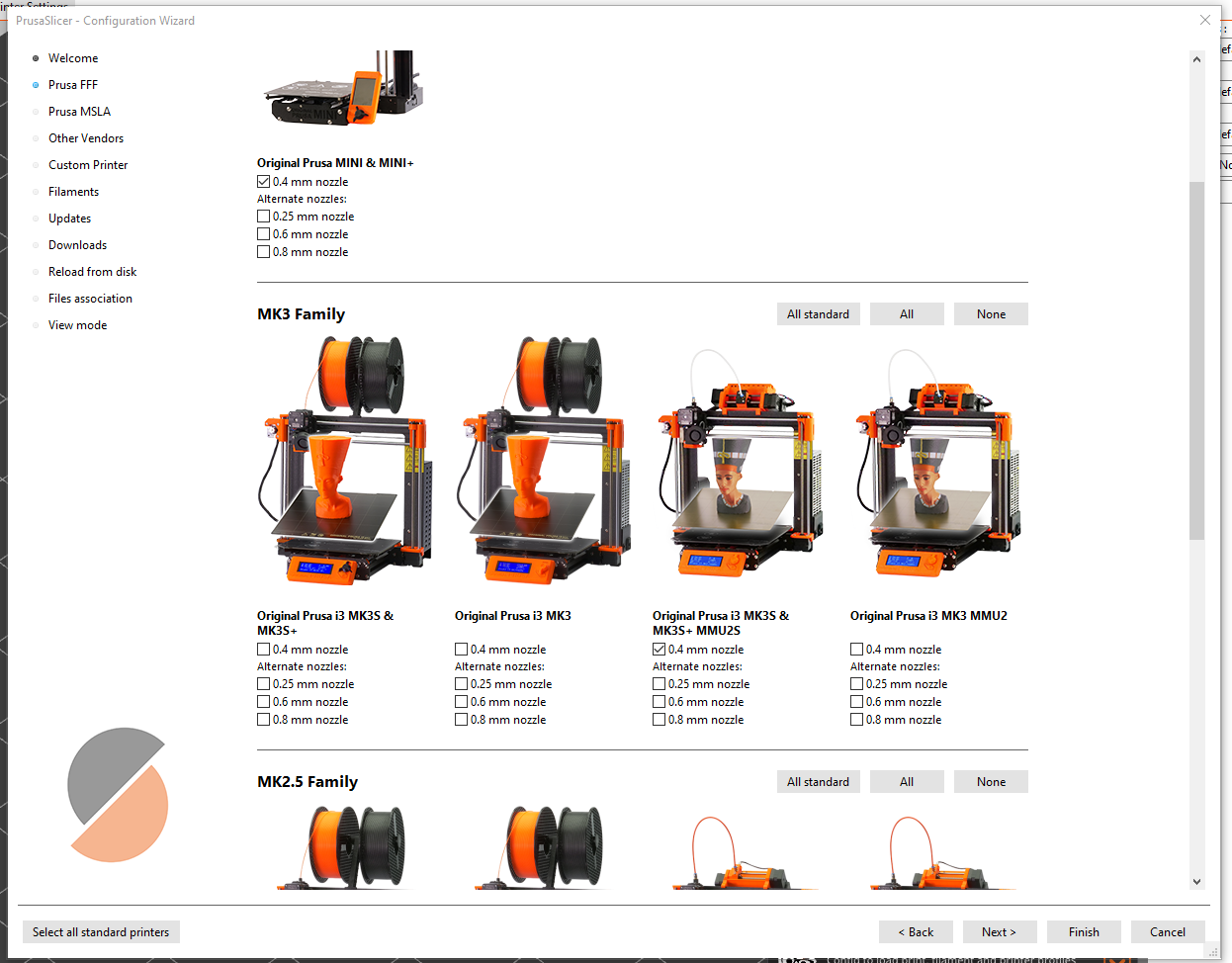
Opening the .exe dropped me right into a NUX (”New User eXperience”), which included selecting which printers I was working with, and setting up some filament profiles. I’m unclear on what filament we have at the space right now, so I opted for the default options.
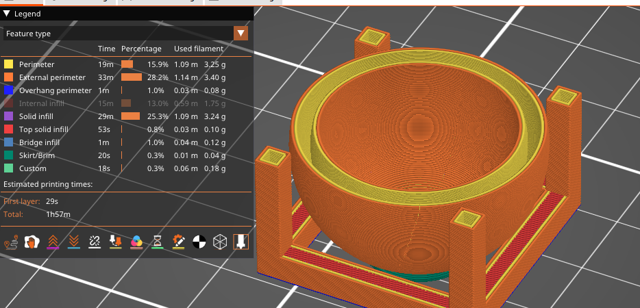
After that I imported my .3mf file of the object I had modeled in Fusion 360, and after selecting default settings, clicked the “Slice” button to get started. At this point I was primarily looking for an estimate of print time, and to see if there were any more hiccups I needed to go back to Fusion to edit out.
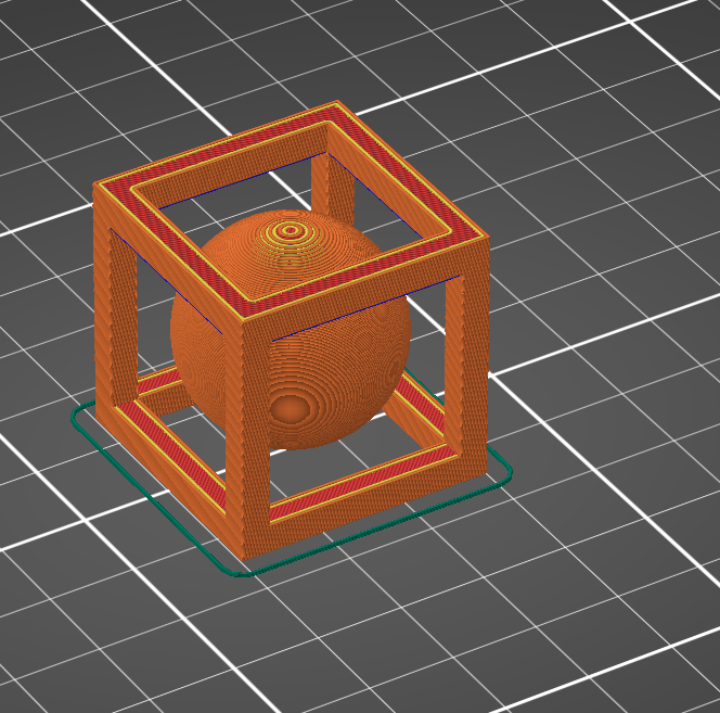
The first, and rather obvious, was that I had left a ball hovering in the air. As I wasn’t printing this in Space, I couldn’t rely on it to just float there like a planet. I knew this going in though, and figured I’d have to compensate with supports in slicer. This first slice was just to get a preview.
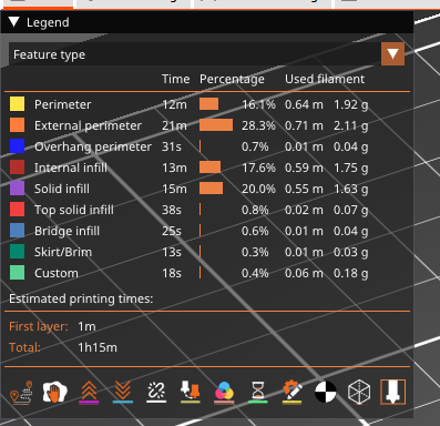
The second issue though, was that I hadn’t hollowed out the shape at all. A remarkable 1/5th of my print time was dedicated just to infill, and given the project’s nature, I didn’t feel I needed it for stability.
So now I figure I’ve either got to figure out how to hollow out internal structure in Prusa Slicer, or see if I can go back in Fusion and see if I can slice off those 15 minutes of print time by using the Shell tool or something like it.
One of the other supposedly new features in this version of Prusa Slicer is warning about my bad slicing decisions:
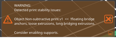
I appreciate the headsup. In the future maybe they’ll release it with some tact. I anticipated the bridging being a potential problem, but given the (relatively) short distance I made the judgement call to let it ride, remembering Neil’s comments on bridging versus distance.
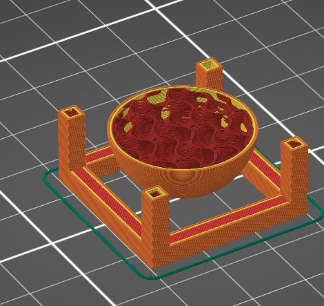
Going back into Fusion and using the Shell tool on the sphere seems great, replacing the sphere with a 3.5mm shell that fits the cube better and I’m hoping won’t need as many supports…
Until I import it into PrusaSlicer. My hollow sphere has actually increased the print time by about 45 mins, or a roughly 3/5 increase in time. Oy.
After going back into Fusion for steps 10 - 13 of modelling, I come back with a newly modified, thinned, chop-top demo part. I fire up PrusaSlicer again and see in all my time spent in Fusion I have taken off… a whopping 5 minutes off the first estimate. Alright, I think I’m done trying to model this part to efficient printing. This is a one off part, so I’m gonna optimize for my time here, instead of print time and good design.
Around this time I also realize the slicer settings by default were set to 0.15mm QUALITY. While I have no idea what exactly that means, I definitely feel like changing it to 0.15mm SPEED seems like the smarter idea here. So really doubling down on the idea, I go 2 steps further and switch to 0.30mm DRAFT, save my work, and speed off to the makerspace. My print time now shows 31 minutes, and I’m deciding to forego supports because I’m honestly curious to see if it’s gonna turn out.
Print time
I load up my exported gcode onto the SD card, pray nobody’s preloaded the card with viruses, and move to the printer. Immediately I encounter an error. This model is a equipped with a “Multi Material Unit”, so even though I don’t want to use more than one material, it’s still playing gatekeeper to the filament and my success. I visit
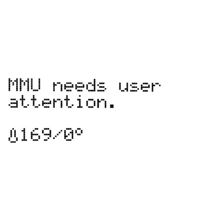
And after some trial, error, more flashing error, and finding tools, I have the error solved with the MMU and am rather proud of myself, as I watch my first FDM print start.
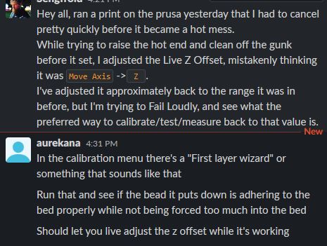
Annnnd then my print failed. Immediately. Didn't even stick to the bed. So I got the big X button, and that seemed to put the kibosh on everything … except I learn afterwards that was the wrong move. You’re supposed to use the scroll wheel to move through the menu and select Cancel Print like there’s no problem at all and you’re not trying to stop a melty plastic machine going rogue in front of you. I didn’t do that, so back to Prusa’s support, this time via Youtube, to figure out how to raise the hotend (hint: It’s not Live Adjust Z, like you hope), and then get the mess of melted gunk off the nozzle before anyone comes in and looks at you funny. The setting to move the hotend around, by the way is Settings → Move Axis → Z for lifting, and the the other axis options for their corresponding directions.
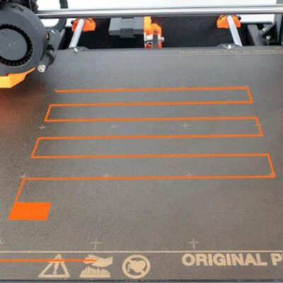
So this time, before printing and after cleaning things up, I appllied a glue stick to the bed in the area of the print.
That print failed due to poor bed adhesion.
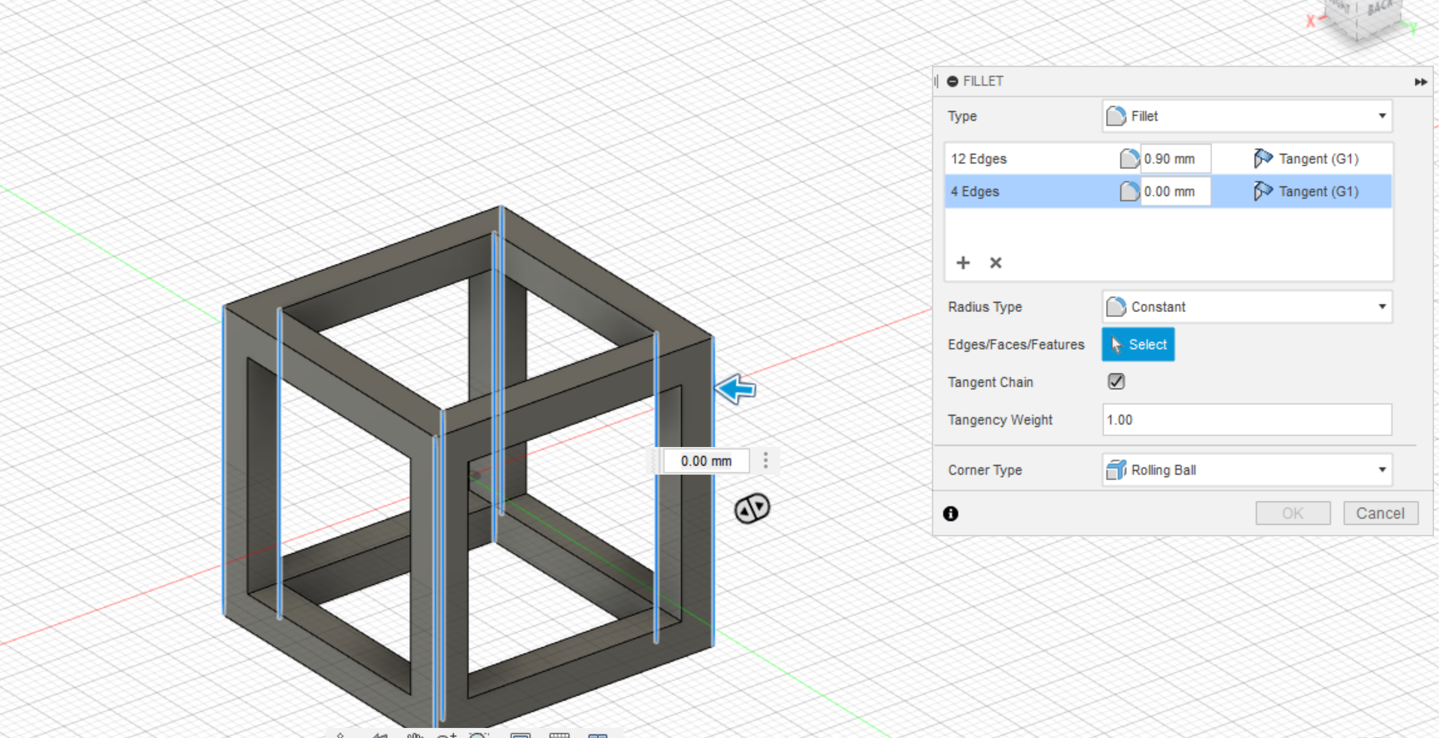
Observing the failures, it looked like it may be an issue I’ve heard brought up during laser week. It seems to be doing great on the sphere, where it’s going in slower circles, but then when it gets to the corners it goes fast as it can and rips them right off the bed.
I had my laptop with me and all my files open still, so it was quick and literal back to the drawing board, to try and add fillets to the edges/corners to hopefully slow down the printhead enough to not tear the first layers off. With my freshly designed file, I headed back to the printer and got a new error. This time the filament didn’t load all the way to the nozzle for some reason. This was a relatively easy fix, using my new found ability to pause a print, and then just pushing the filament further from the spool side. That seemed to do the trick, so I resumed the print annnnnnnd… Watched it fail due to poor bed adhesion.
At this point I had one more try left in me, so started by pre-heating the bed about 12 degrees celsius above the default settings for PLA, then turned it up during the print, as well as using bumping up the Live Adjust Z to really go all out, in addition to copious amounts of more gluestick.
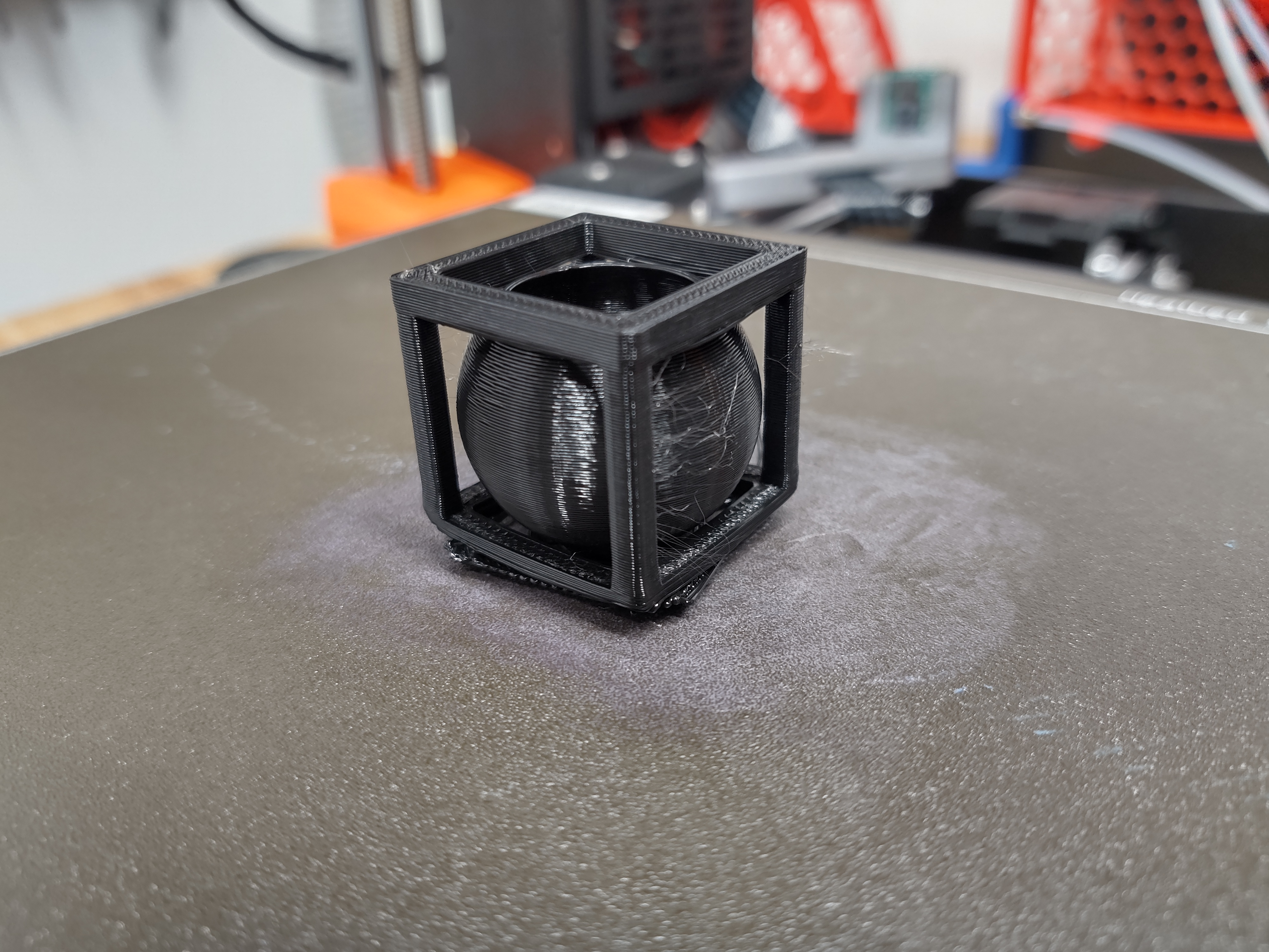
The results were, well dissapointing. The print is currently printing, and made it past its initial failurs at bed adhesion, but is gonna be extremely layer shifted and slightly short of spaghetti. But at this point I’m out of time for the week and have to head home. I take solace in knowing that I did technically complete the assignment; it was to design and print something that isn’t easily printed subtractively, NOT something that’s easily made additively.
After The Fact, or Playing Catch-up
Week 6: Given my issues with the Z-Offset, I hopped on the makerspace slack to make sure I could set things back to the way I found them. In the process, also hopefully improve my future prints. (Cue Snow White’s Someday my prints will come)
I’m referred to this page on the Prusa help documentation
And somewhere between Aurekana’s comment about ~“having to follow this procedure often due to swapping beds for his prints” and sorting through my own documentation to clean it up for the repo, I notice that I missed something critical from my notes on the FDM printer. Literally my 3rd note from the training said to use the smooth bed for PLA. I assumed that PLA would be the most basic printing material, as I feel it’s the one I hear about most commonly, and therefor all the defaults would be set up for it. This was a dumb assumption, and I’m kicking myself a little on it now, as my print was able to complete but specifically had horrible bed adhesion. I had stuck with the general purpose Textured bed that was already on the printer. Well, I took this course to learn, and if I didn’t take note I’m not sure I would have caught this as qucikly. Learning experience indeed.
3D Scanning
I have some extremely light background in photogrammetry from my last phone, which came with a 3D scanner app included. It was relatively easy to use and grok the concepts and limitations of photogrammetry that way. Due to the limitations in Supply-side Time though, I chose to forego scanning during the week to focus on the areas less familiar to me, namely FDM and 3D design, since I knew would require more focus. The time I spent on Scanning durring the week was uncovering which scanner we had in the space (Afinia ES360), why everyone hated it (poor proprietary software, even poorer results), and what the alternative was (setting up SKAnect using the kinect burried in the space, within specific use cases). Given the sheer amount of hassle, and that the camera was broken on my old phone with decent software, I decided to holding-off until a better option appeared.
Looking into more this week, it appears there’s a, er, “friendlier” version released on XDA Forums by peterteter, working off initial effort by nullbytepl. This version is not manufacturer-restricted, so having a non- Sony phone shouldn’t prevent me from using it. The steps to get going here are effectively:
- Download the modified APK (android install file)
- download an obb file to help the app validate
- verify minimum requirements are met via Camera2 API Probe
- Copy obb file to
Android/obb/com.sonymobile.scan3d/on Internal Storage- Note: obb file needs to be named
main.VERSION_CODE.com.sonymobile.scan3d.obb.
- Note: obb file needs to be named
So let's get downloading!
.jpg)
