
8.Electronics production
Group Assignment
Electronics design
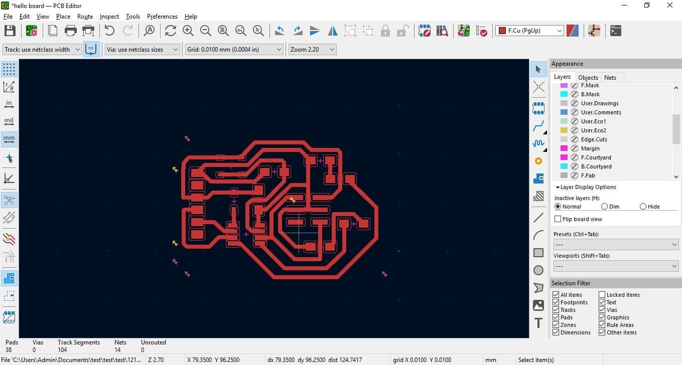
During week 6, we completed a thorough electronics design utilizing attiny 412, covering all fundamental aspects of design. Now, in regards to manufacturing, we must choose a suitable production method. In week 6, I created two designs: one in Fusion 360 for amusement and one in Kicad for practicality. After careful consideration, I selected the design from Kicad for production week.
Production Prerequisites
At the beginning of the week, we were instructed to convert all files to .png format to work with fabmods. However, Kicad does not support png files, and although I heard there are extensions available, I opted to use Inkscape instead. This was because I also needed to draw an outline for my design.
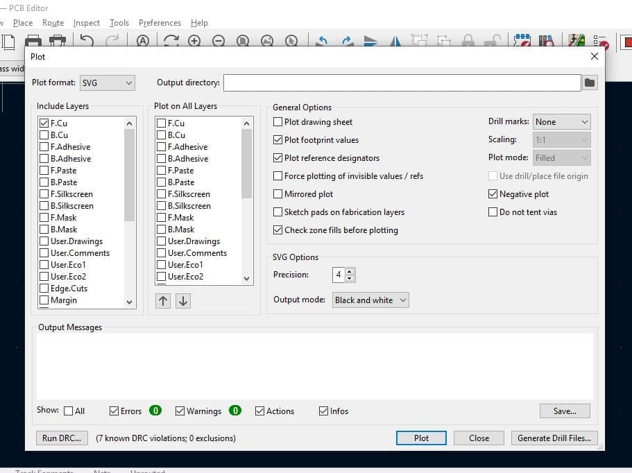
To convert files to svg format in Kicad, you can follow these steps: Go to "Files" and select "Plot". From there, choose the layer that needs to be converted to png format. In my case, I selected the F.cu layer. Then, select "Black and White" as the output mode and choose "Negative Plot" to invert the colors of the image. Finally, click "Save" to save the SVG file to the specified location.
Inkscape
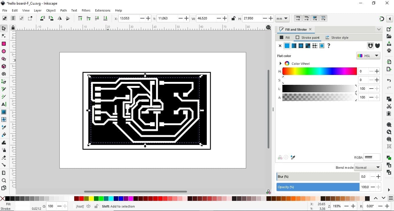
To post-process my png file, I utilized Inkscape, which is a versatile and effective design tool for converting and editing both SVG and PNG files. I began by selecting my SVG file and adding a box around it to ensure that the drilling and milling operations would have the same origin. Next, I created two PNG files: one with the box and PCB layout, and another with the box for the drilling operation.
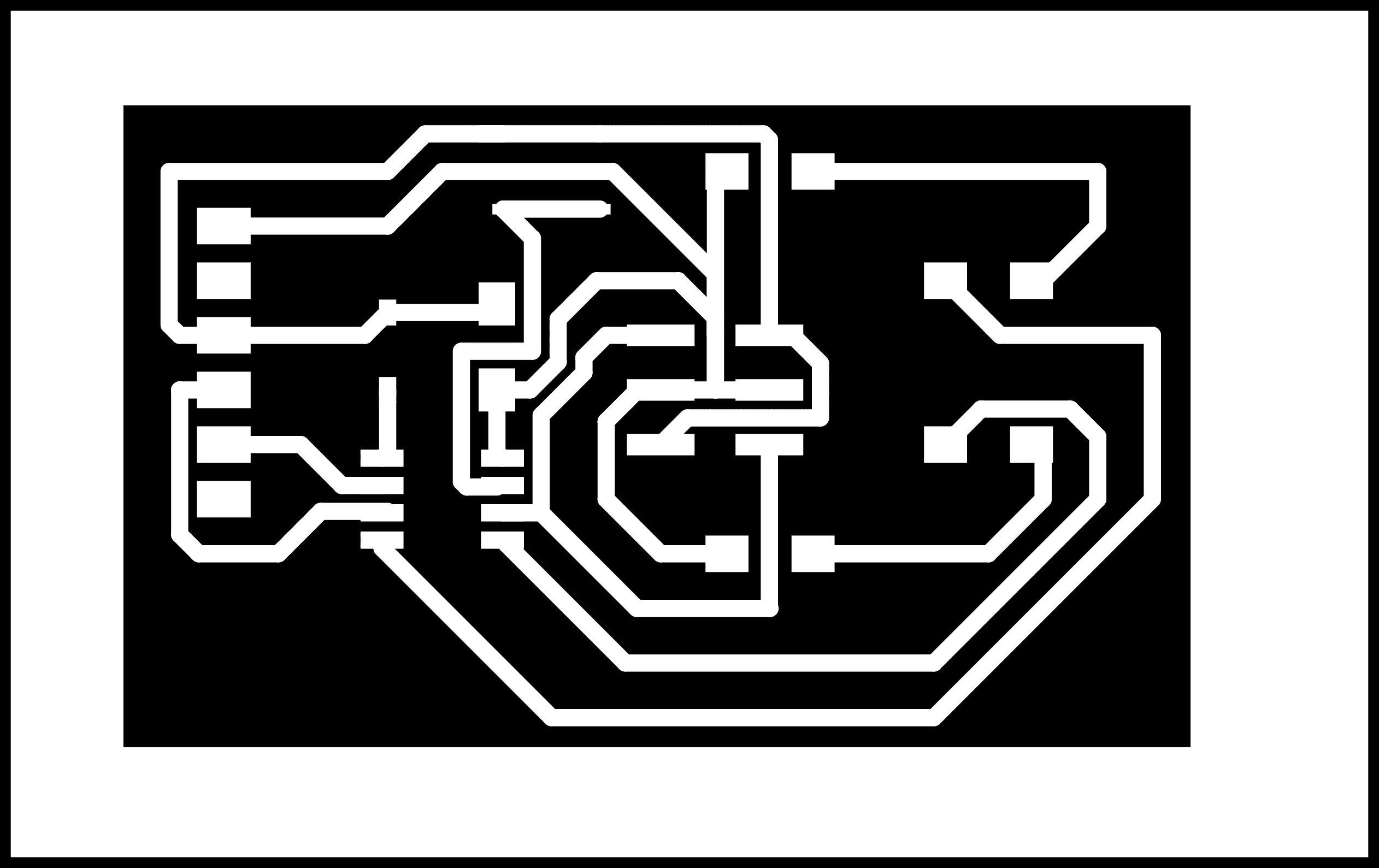

the second one is actually the png of the box
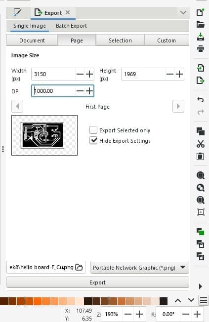
To convert SVG files to PNG, it is important to consider the DPI (dots per inch) of the output file. A DPI of at least 1000 should be selected to ensure good resolution. On Fabmods, the only way to adjust the size is by changing the DPI, so optimizing this aspect is crucial. To do this, go to "Files" and select "Export". Then, choose the desired DPI and save location, and save the file in PNG format.
Roland
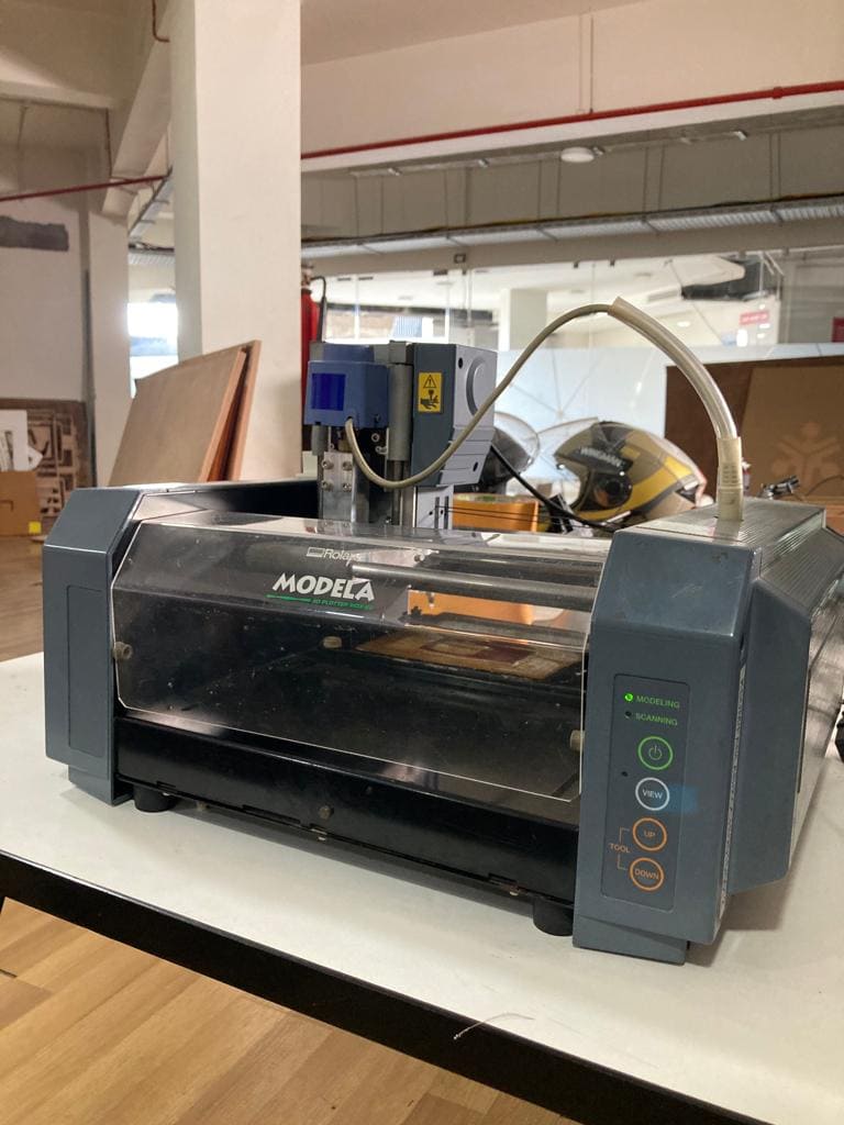
The Roland Modela milling machine is a desktop-sized milling machine that is used for precision milling, drilling, and carving of a variety of materials such as plastic, wood, wax, and metal. It is manufactured by Roland DG Corporation, a Japanese manufacturer of digital fabrication tools and equipment.
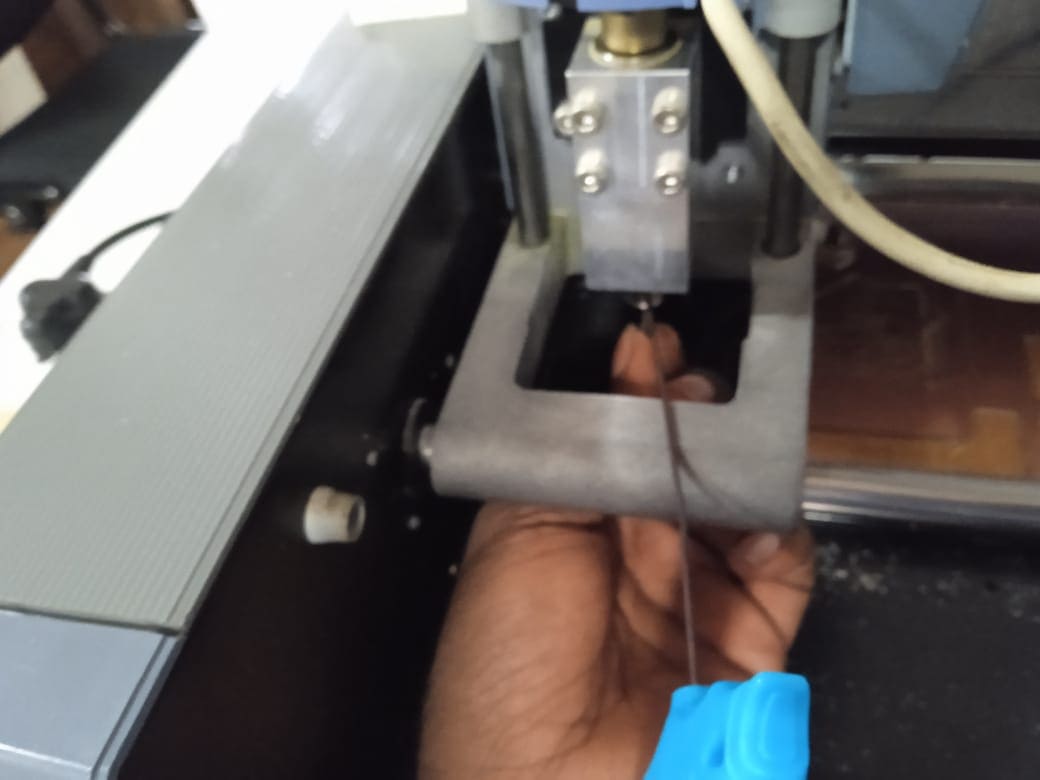
Before starting the milling, we need to select the origin for the machine. The X and Y axes can be adjusted in modules, and the Z-axis needs to be calibrated manually using an LN key. We can change the height of the tool to fix the Z-axis, and after fixing the axis, we are ready for milling
During the milling process, choose the milling type and tool type, and adjust the feed and cut depth if required. Afterward, select the calculate option to view the machine-generated toolpath. If satisfied with the toolpath, click on the send-to-port option to begin the milling process.
Pico
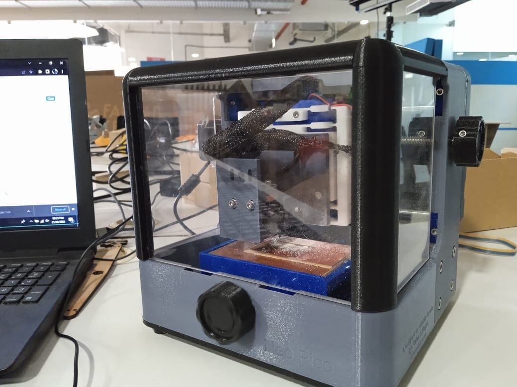
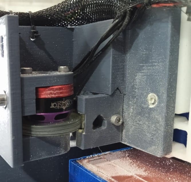
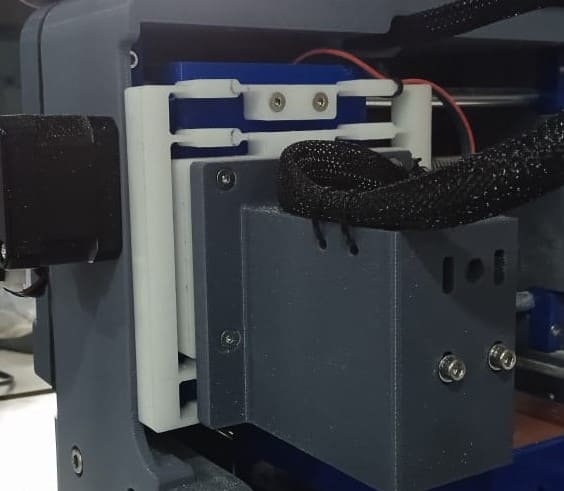
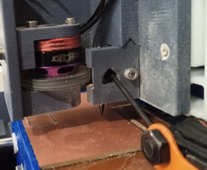
The machine was the brainchild of Rahul,one of our instructor. The idea was to create a portable and low-cost PCB milling machine. The Pico is itself beautiful, and its tool changing and calibrating the Z-axis is the same as the Roland Modela. Pico is a fully 3D printed design that can be made easily for less than $500. The Neo Pico has a smaller size compared to other milling machines and is easily portable. The whole design consists of 3D printed parts, and considering the amount of 3D printing, it can be built and made operational in less than 3 days.
The Pico has a work area of 100mm x 70mm and a jog height of 2mm, so while fixing the Z-axis, we need to be more careful. The Pico consists of a different design with flexures for Z-axis movement and a friction drive to drive the motor. The motor driving the friction drive runs at an RPM of 1400 and has a speed of 40mm/s. Overall, the Pico is no less than a normal PCB milling machine.
Setup
The Pico takes input in the form of G-code, which is a programming language used to control CNC machines. Therefore, we need to generate the G-code to run the Pico. Luckily, we have Fabmods, so generating G-code is not an issue.
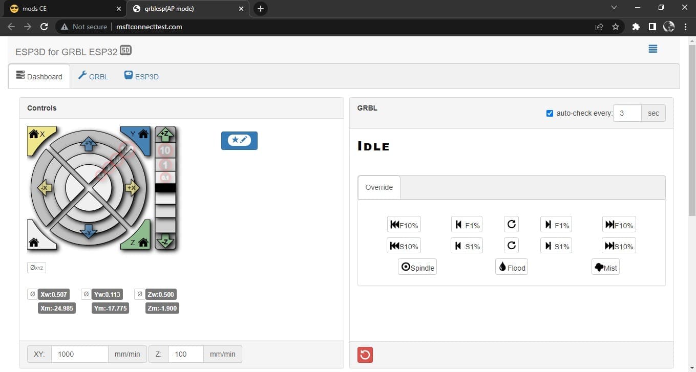
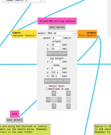
To start the machine, plug in the power supply, and the machine will start with a bang. The Pico uses a power supply of 12V and 5A DC current. After connecting to power, switch on the Wi-Fi and connect to Garble ESP. The interface to control the Pico will be opened automatically in your browser.
From the window, we can change the X, Y, and Z coordinates of the machine and fix the origin. The machine has no true origin, so when you switch it on, the position at which the machine is turned on becomes the origin. In order to set up the origin, we need to jog the machine using the jog tools. The arrows are in multiples of 10, ranging from 0.1 to 100 mm, even though it doesn't have that much bed length. So be careful while playing with the jog tool, and the Z-axis has only 2 mm movement, so be careful while moving or it may cause a toll or two.
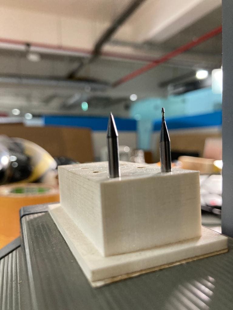
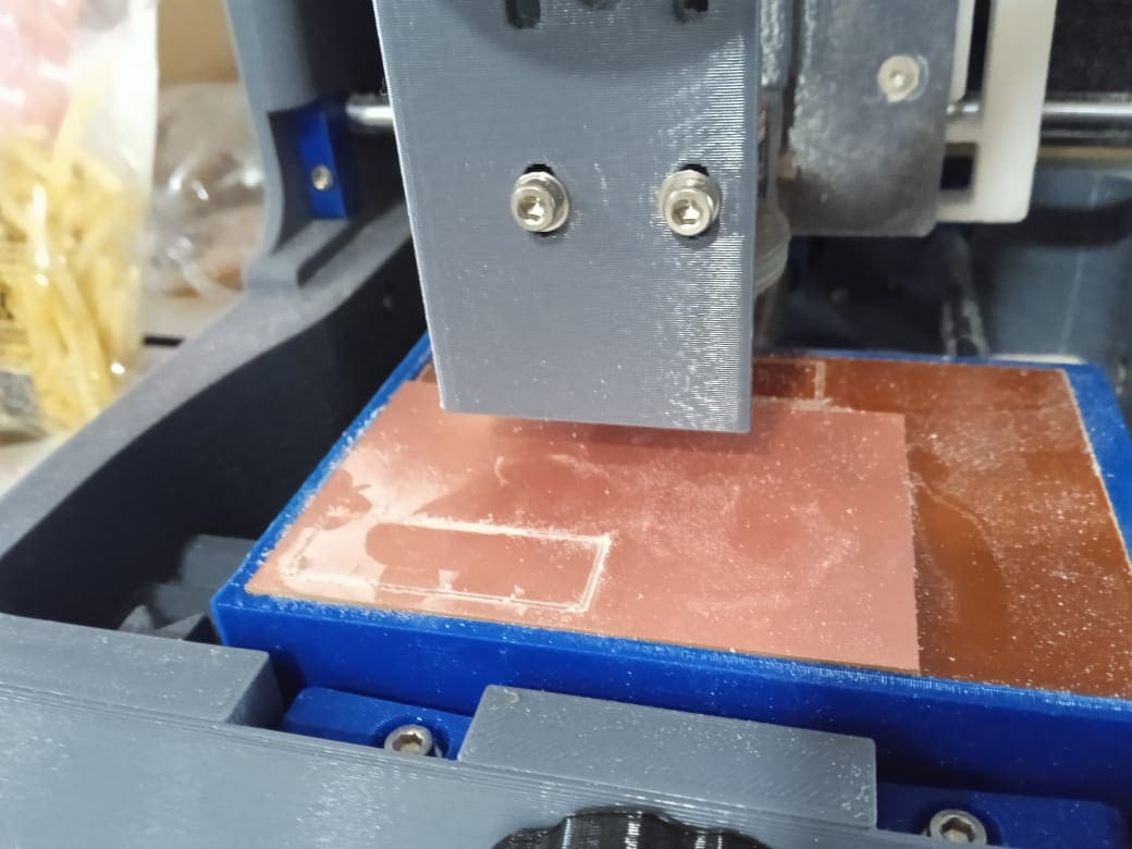
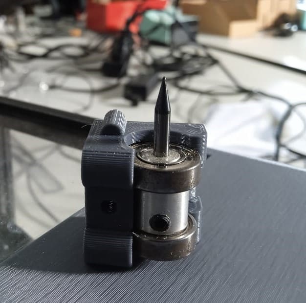
To set up the tool, we can remove the tool holder using an Allen key and change the tool. We are using a 16 mill tool for milling and a 32 mill tool for cutting, so the tool needs to be changed. The Z-axis also needs to be adjusted for the tool length. Like in the Modela, we need to calibrate the Z-axis manually. First, we need to place the tool higher and adjust the height. First, take the tool to the bottom of the movement, which is Z max, and according to our cut depth and jog height, change the height and tighten the tool. The position of the Z-axis must be selected in such a way that there should be enough cut depth and jog height. Otherwise, it will be a problem.
Now we are Ready to mill.
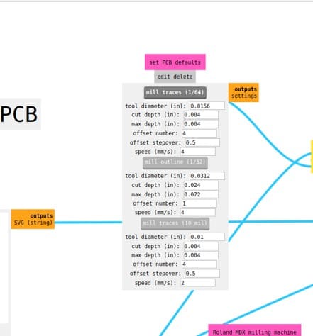
Mods
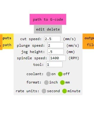
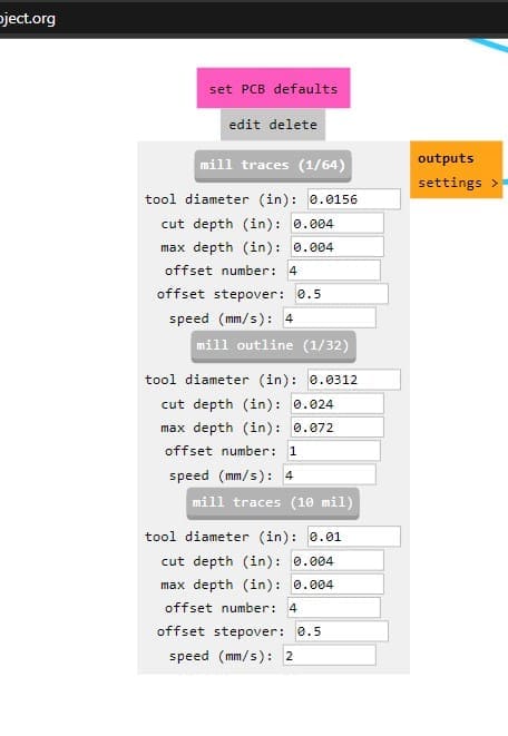
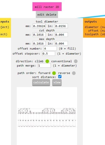
As the machine only takes input in the form of G-code, we need to convert the PNG or SVG format into G-code. Luckily, we have mods, so the PNG files can be converted into G-code using mods. In that, we need to change the settings according to our machine. We need to convert the spindle RPM to 1400 RPM and the jog height to 0.5 mm. After selecting the tool for milling or cutting, we can hit calculate, and the G-code will be downloaded automatically.
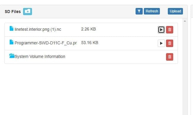
After downloading the G-code, we can go to the machine interface and upload the code. Or, to run an already existing code, press refresh, and then press the play button to run the G-code. The machine will start milling.
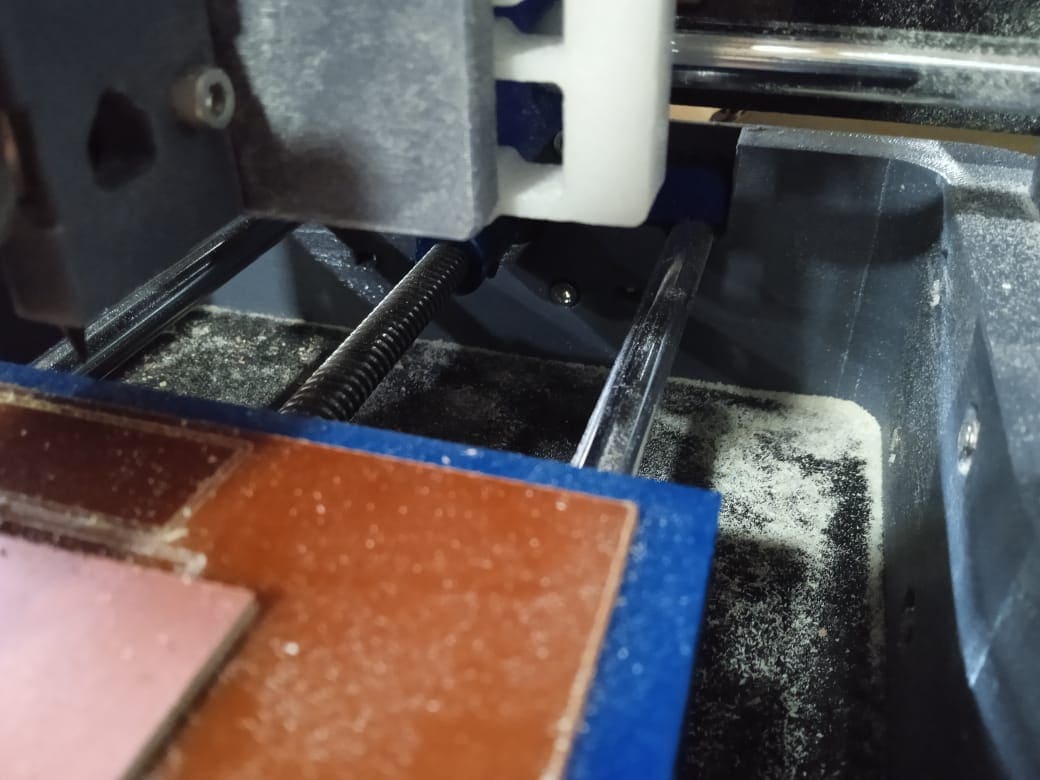
Although I operated the machine in an unsafe manner by opening the lid, it is important to note that the machine itself is very safe. However, I strongly advise against imitating my behavior.
what do I have to say
Even though the machine is great and affordable, I will be focusing on the negative reviews, and I don't expect to find anything positive because someone is waiting for my negative reviews.
- Due to the limited jog height, which is only 2.3 mm for the total movement of the z-axis, it's crucial to calculate the position of the z-axis every time to avoid any potential damage to the tool when working with non-uniform PCBs. In case the PCB height exceeds 1.5 mm, milling it would be impossible. Additionally, to accommodate for the limited jog height, I had to set it at 0.5 mm, which is not entirely safe for the tool.
- The machine does not have a definite origin, as the position where it is switched on is automatically selected as the origin. Furthermore, the machine lacks limit switches in any direction, which makes it necessary to install them.
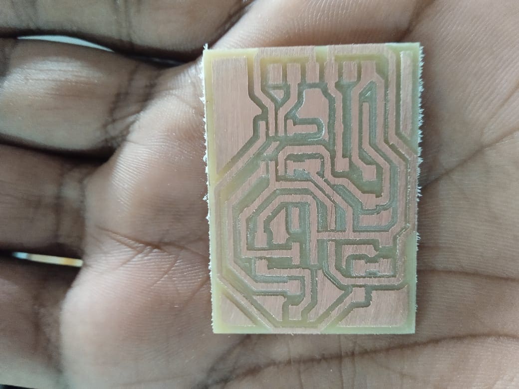
- The movement of the Z-axis is not consistently optimized. While milling my PCB, it sometimes functions perfectly, but at other times, it overcuts. During a test cut, it milled more depth than anticipated, even though it was functioning properly previously.
- The base plate is not necessary for the Pico because it is too small in size to allow for cleaning through the gap. However, if the bottom is open, we can easily clean it by lifting up the machine. Otherwise, the base plate needs to be removed for cleaning purposes.
Soldering
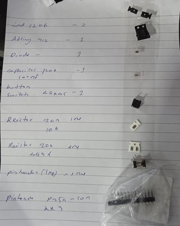
My soldering experience is limited, especially when it comes to surface soldering. The initial step involves gathering all the necessary electronic components and cross-checking them with a list of components on a sheet of paper. I prefer using single-sided tape to attach the components, bending them slightly at each end to keep them in place on the paper. This technique prevents confusion during the process.
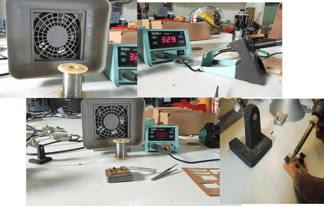
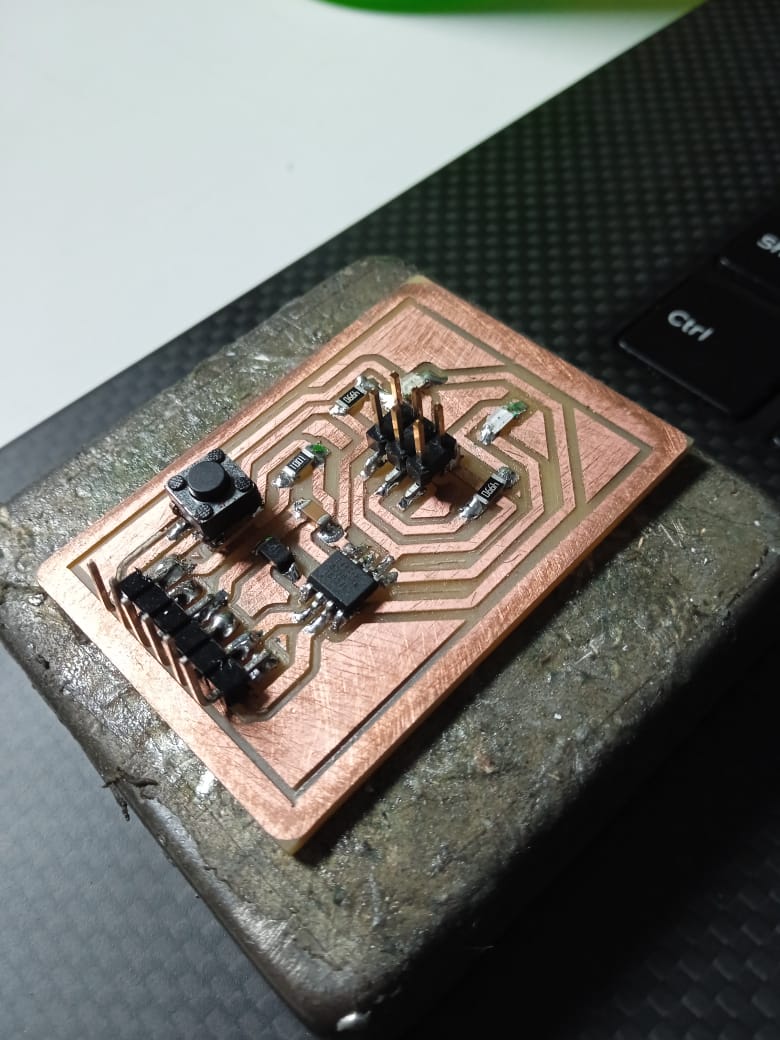
After assembling all the necessary materials, I began soldering the components together using a soldering iron. Once the soldering was complete, I conducted circuit testing and made any necessary resoldering adjustments. After several rounds of testing and fine-tuning, I was pleased to have a fully operational circuit.
Programming
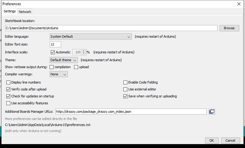
The Arduino IDE is a popular software development platform for programming microcontrollers, including the ATtiny412. To program an ATtiny412 using the Arduino IDE, the first step is to install the ATtiny boards package in the IDE. This can be done by selecting "Tools" from the top menu bar and then choosing "Boards Manager." From there, search for "attiny" and select the "ATtiny" boards package from the search results, followed by clicking the "Install" button.
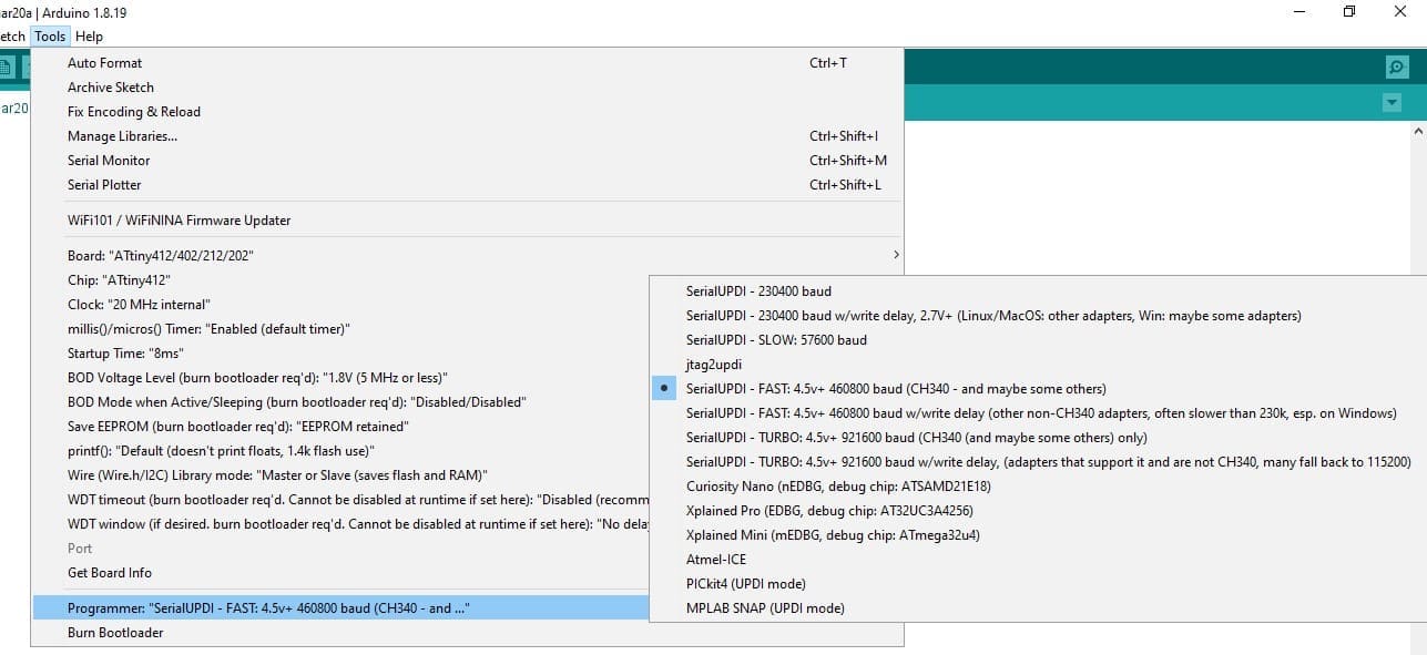
Once the ATtiny boards package is installed, the next step is to connect the ATtiny412 to the computer using a programmer such as USBtinyISP or AVR ISP MKII. After the ATtiny412 is connected, select "ATtiny412" as the board type from the "Tools" menu in the Arduino IDE. This will allow the IDE to recognize the microcontroller and provide the appropriate settings for programming it.
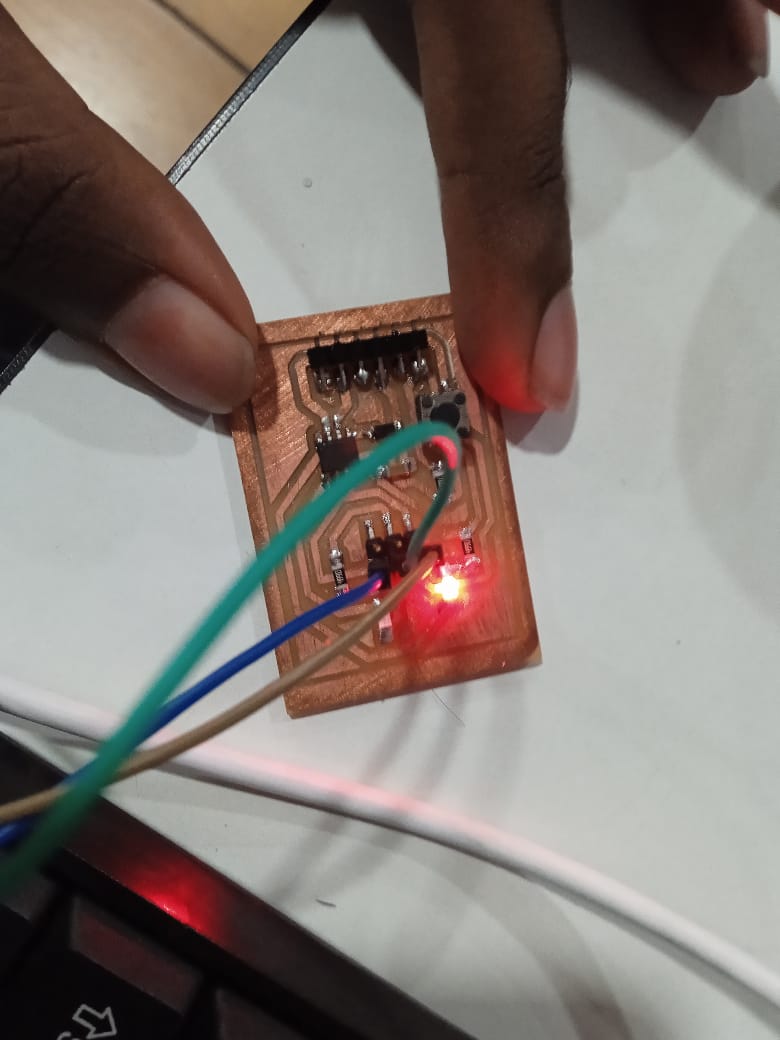
The "blink" program is a simple program commonly used to test an LED and ensure that it is properly connected to the microcontroller. The program turns an LED on and off repeatedly with a set time interval. This program is often one of the first programs that beginners learn to write when they start learning microcontroller programming.
*/

// the setup function runs once when you press reset or power the board
void setup() {
  // initialize digital pin LED_BUILTIN as an output.
  pinMode(2, OUTPUT);
}

// the loop function runs over and over again forever
void loop() {
  digitalWrite(2, HIGH);  // turn the LED on (HIGH is the voltage level)
  delay(1000);                      // wait for a second
  digitalWrite(2, LOW);   // turn the LED off by making the voltage LOW
  delay(1000);                      // wait for a second
}
As for the program with the switch, it is designed to turn an LED on and off depending on whether a switch is turned on or off. In the program, the switch is connected to an input pin of the microcontroller, and the LED is connected to an output pin. The program reads the state of the switch and turns on the LED if the switch is turned off, and turns off the LED if the switch is turned on.
  int switchPin = 4;    // Assign switch pin
  int ledPin = 2;       // Assign LED pin


  void setup() {
    pinMode(switchPin, INPUT_PULLUP);   // Set switch pin as input with pullup resistor
    pinMode(ledPin, OUTPUT);            // Set LED pin as output
  }

  void loop() {
    int switchState = digitalRead(switchPin);   // Read the state of the switch
    if (switchState == LOW) {                   // If switch is pressed
      digitalWrite(ledPin, HIGH);               // Turn on the LED
    } else {                                    // If switch is not pressed
      digitalWrite(ledPin, LOW);                // Turn off the LED
    }
  }