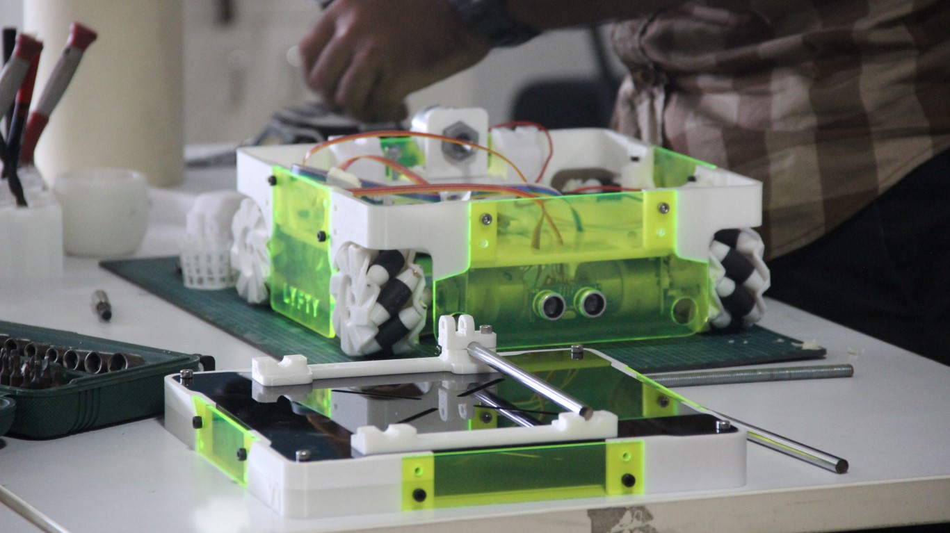
Final project - LYFTY
— The presentation slide —
CONTENTS
The idea
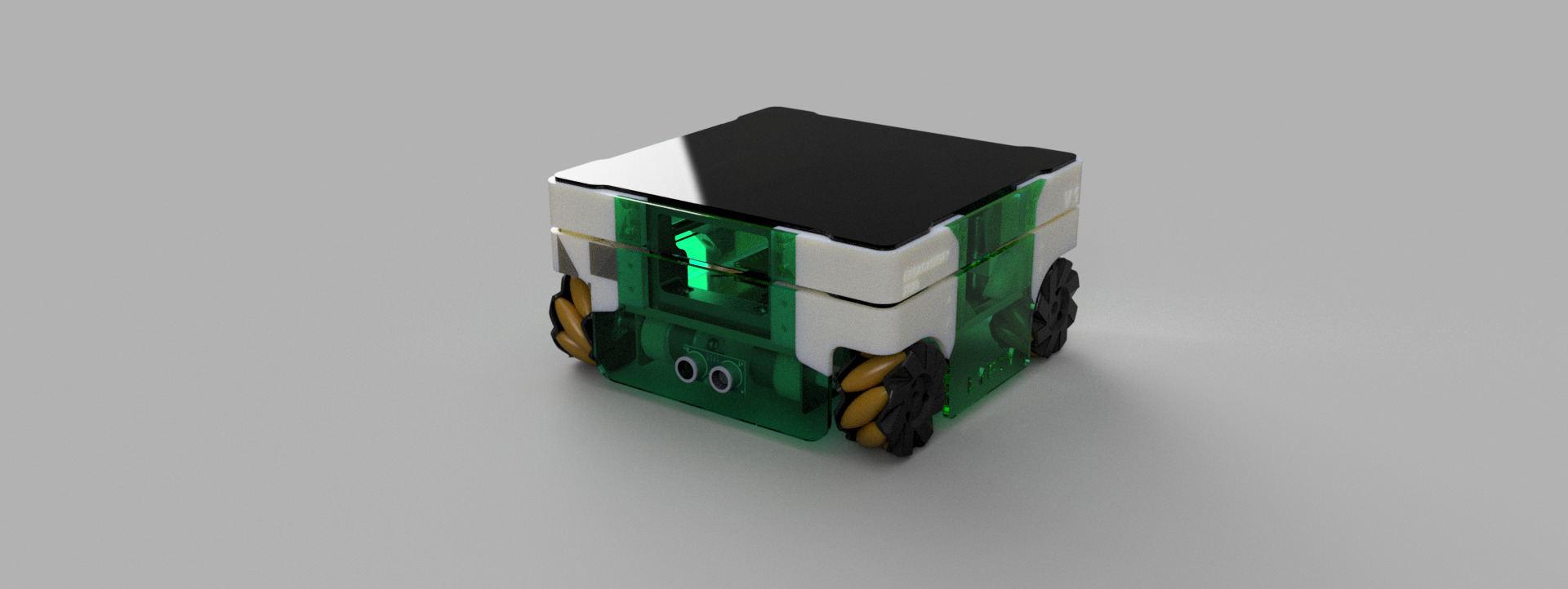
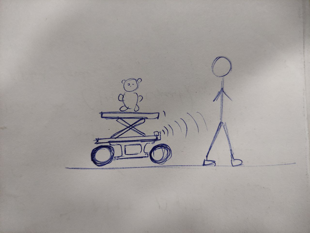
The idea is to create a robot that carries your things and follows you around the lab,
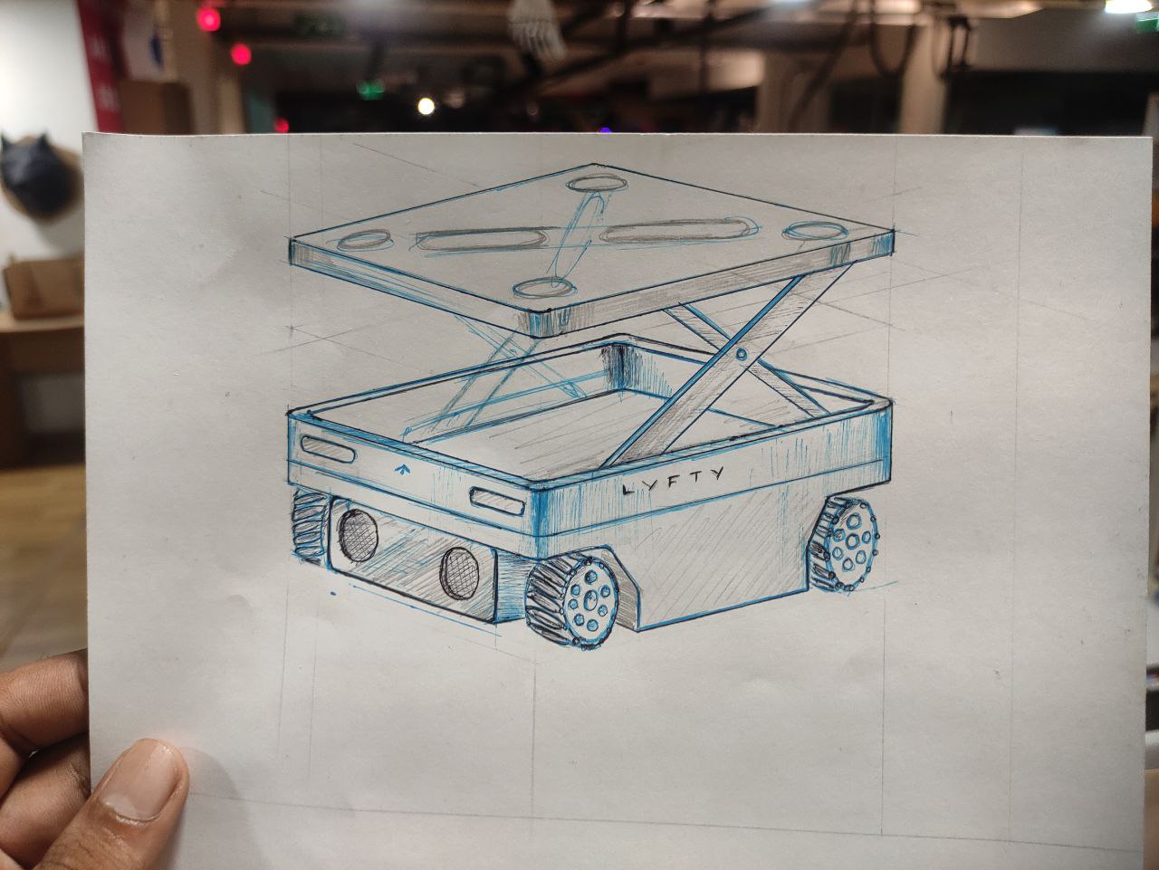
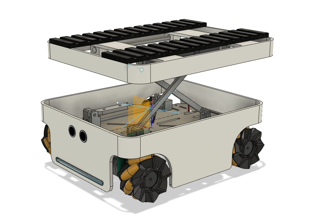
- this design was done in Fusion 360, on the second week (click here to check it out) as a part of the cad design this was just the concept inspired by an actual vehicle
- a simple visualization of how the bot is going to work
At this point, i came to the conclusion that i going to make an AGV “Automated Guided Vehicle.”
the automation part will be in the version two, so as for the final project im just making a ground bot
What is an AGV ?
AGV stands for Automated Guided Vehicle. It is a mobile robot that is designed to move materials and products within a manufacturing, warehouse or logistics environment, without the need for human intervention. AGVs are programmed to follow a specific path or route,
Here are some examples:
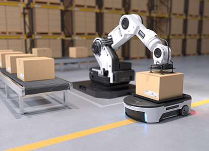
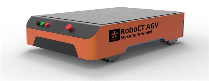
inspired from these and with some researches i have decided to add some features that suits my requirements
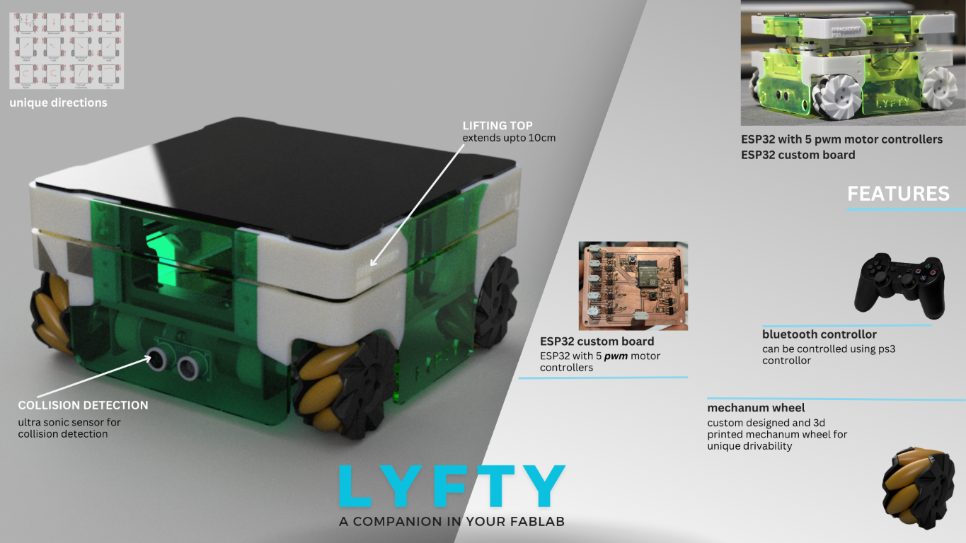
Features of this project
here are some of the features that im hoping to add
- mecanum wheel as the wheel as mecanum wheels provide increased maneuverability, improved efficiency, flexibility, reduced wear, and tear,
with these the vehicle can go latterly also do crab movements which will be a cool feature to have.
- remote controlled for now
will be using a play station 3 controller, or will make a mobile app with mit app inventor
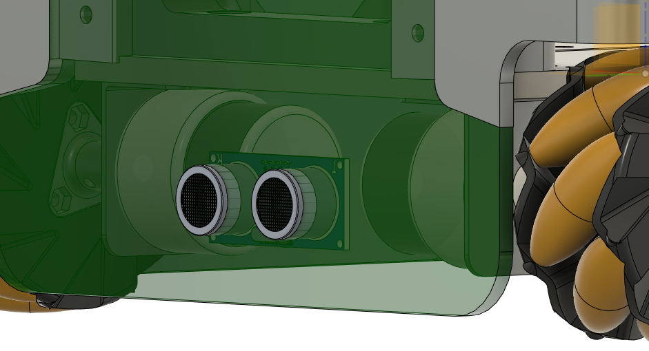
- sensors
Ultras sonic sensor, for edge detention,
- lifting mechanism
add a scissor lift mechanism to lift things and move them around.
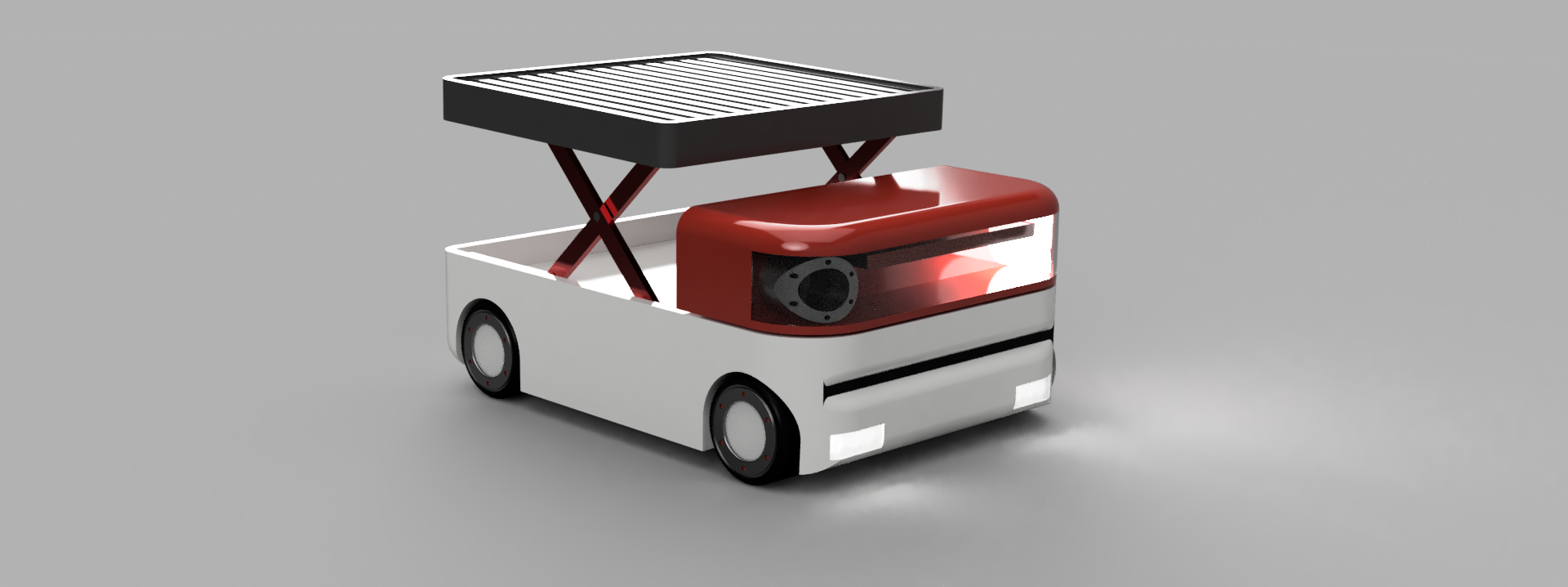
- with all these features and concepts in mind, i made some sketches
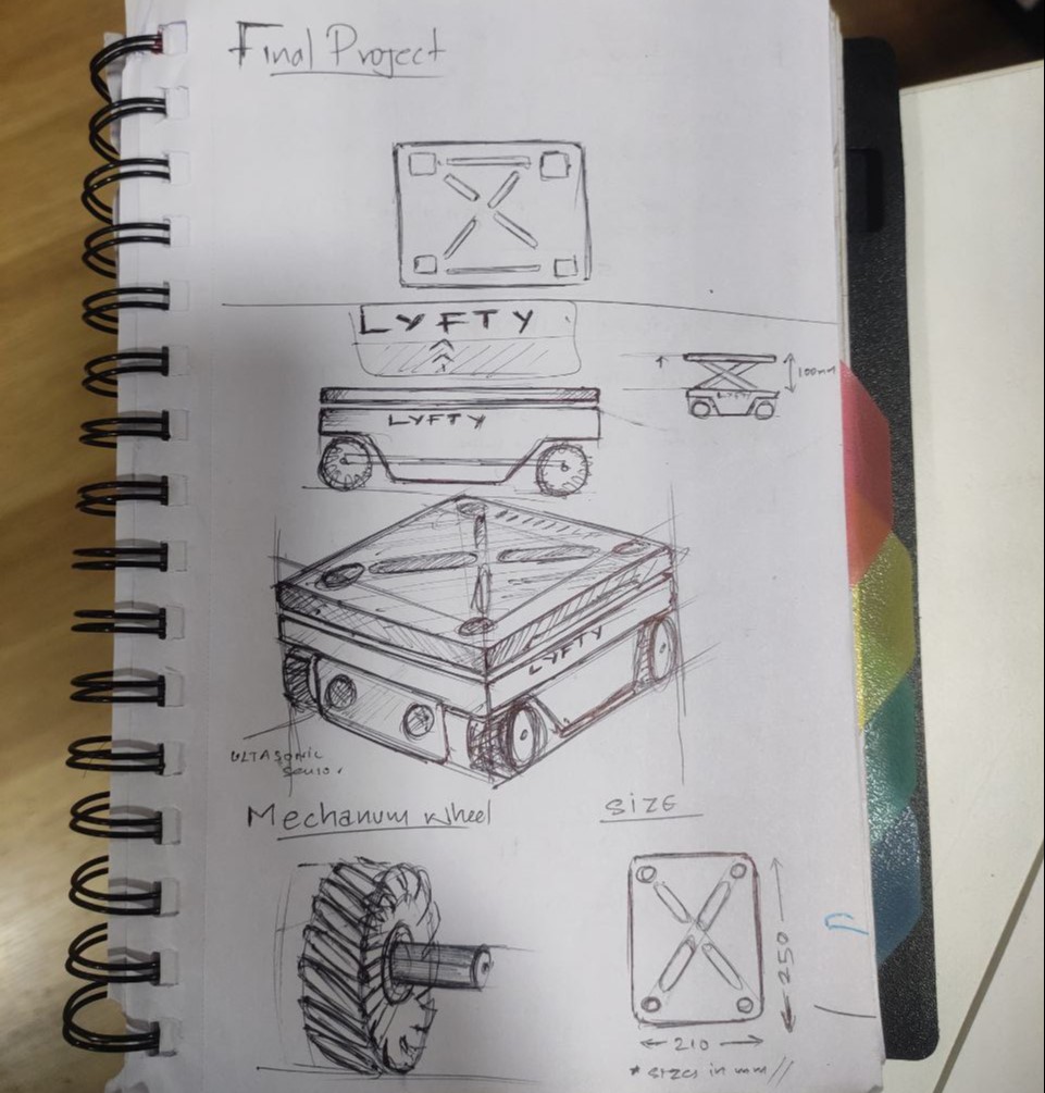
- the initial idea of the bot adapted to a more simpler and efficient design that can be done in the lab with the resources we had
- a more improvised design
Project planning
This whole project is divided into 4 Phases
Phase 1
- designing the mecanum wheel, fabrication
- mecanum wheel was placed first as it was the most integral part of the project.
the rest of the things will be based on that, after fixing the whole dimension of the bot
Phase 2
- CAD design of other components
- make BOM for this project
Phase 3
- chassis, fabrication, and assembly of motors and components
Phase 4
- Electronics, designing the PCB, fabrication.
- integration of electronics to the chassis,
- run test runs with the chassis
Phase 5
- fabrication of the frame, assembly. as the chase will be just mounted on the chassis
- fabricating and assembly of the top and the lifting mechanism
Phase 6
- programming,
- testing
- debugging
Phase 1
Mecanum wheel
here the idea is to design a mecanum wheel from scratch, for that I had to learn how it works in detail, for that I referred to some research paper, which you can read it here
- the benefits of using the mecanum wheel that attracted me the most
- Omni directional with a combination of more than 3 wheels
- no auxiliary steering needed
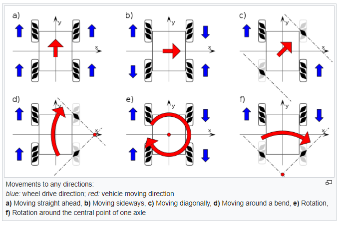
- working of the mecanum wheel, the effects of individual wheel movements
- a basic sketch for understanding how to design the wheel
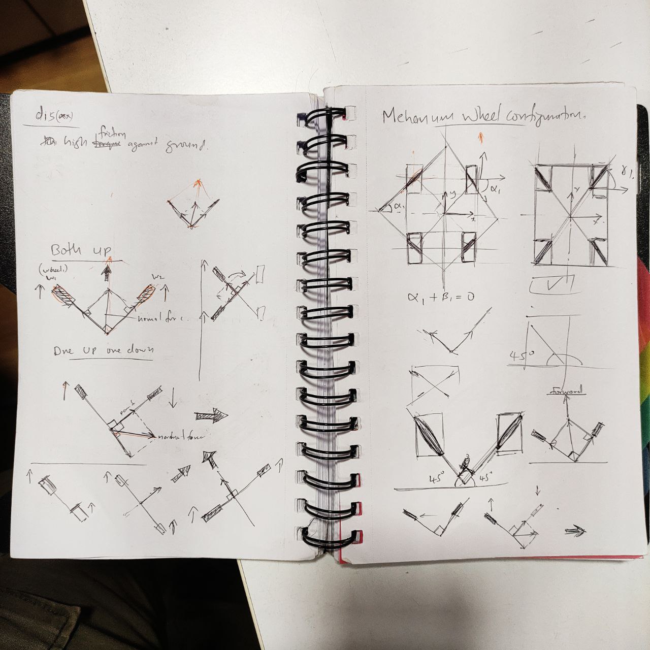
- there were different configurations for the wheel in different directions, and the result movements will be varying for each.
- for this project, i choose this configuration which was easy to fabricate.
Cad design of the wheel
with these learnings, I started designing the wheel in Fusion 360
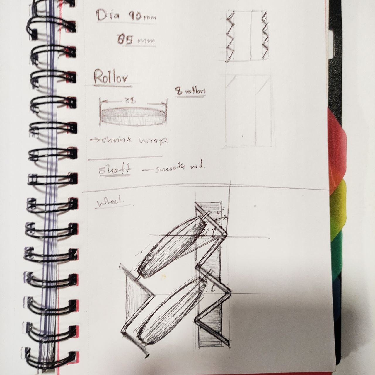
- The basic outline sketch, these will be the dimensions
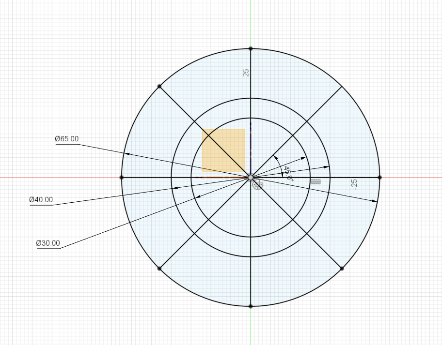
- the process of designing the mecanum wheel
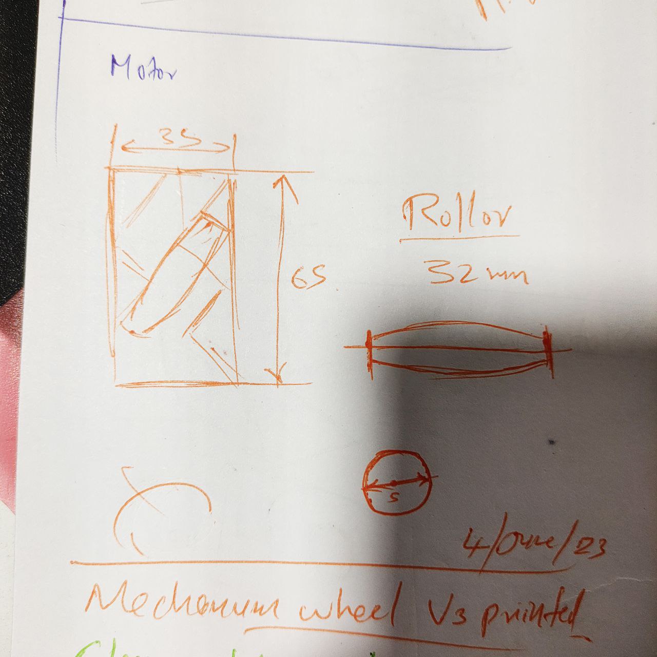
- coupling to connect to the motor
- roller
there are 8 rollers is a single wheel, it is inclined at a 45-degree angle,
the difficult part in designing the wheel was the placement of the roller, but after a lot of attempts I found a way, to design the roller at a 45-degree and cut that hole from the full body, you can see that in the above video
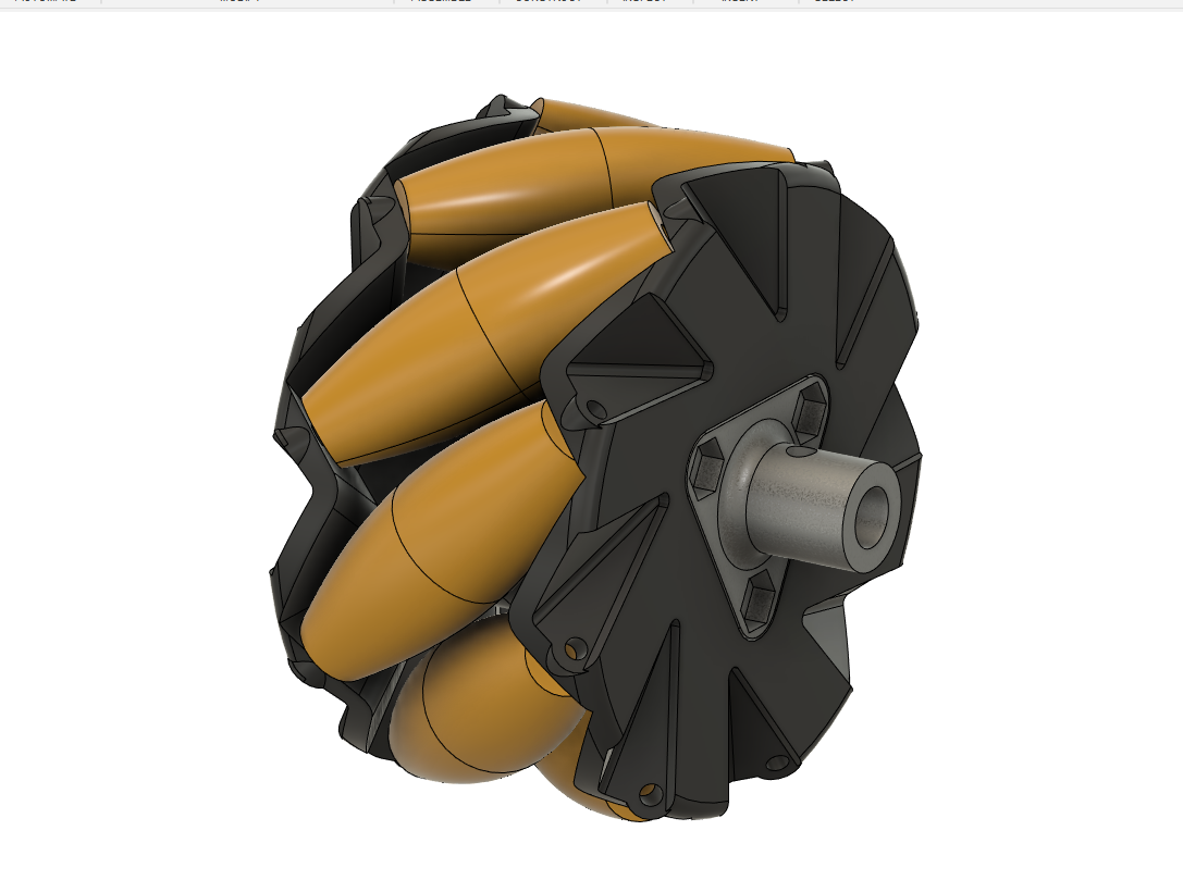
- Exploded view of the mecanum wheel
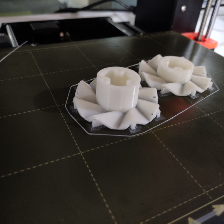
- 3D printing the parts
- these were the first prints,
.jpg)
- but after the assembly, the rollers in the wheel didn't work as it was tight and was not able to roll freely with a 3D printed notch, and the screw hole clearances were incorrect.
- so had to redesign it, considering these problems
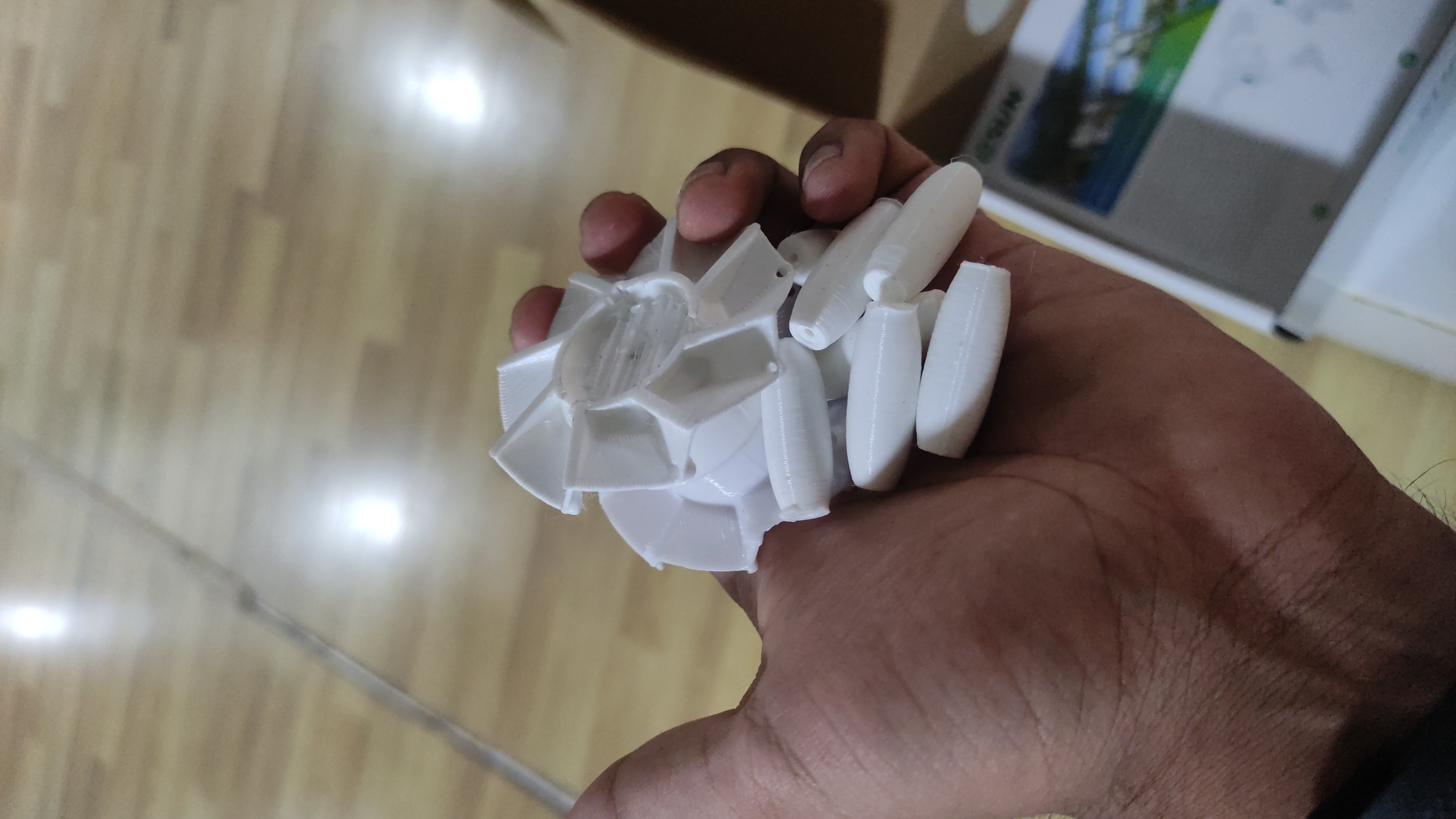
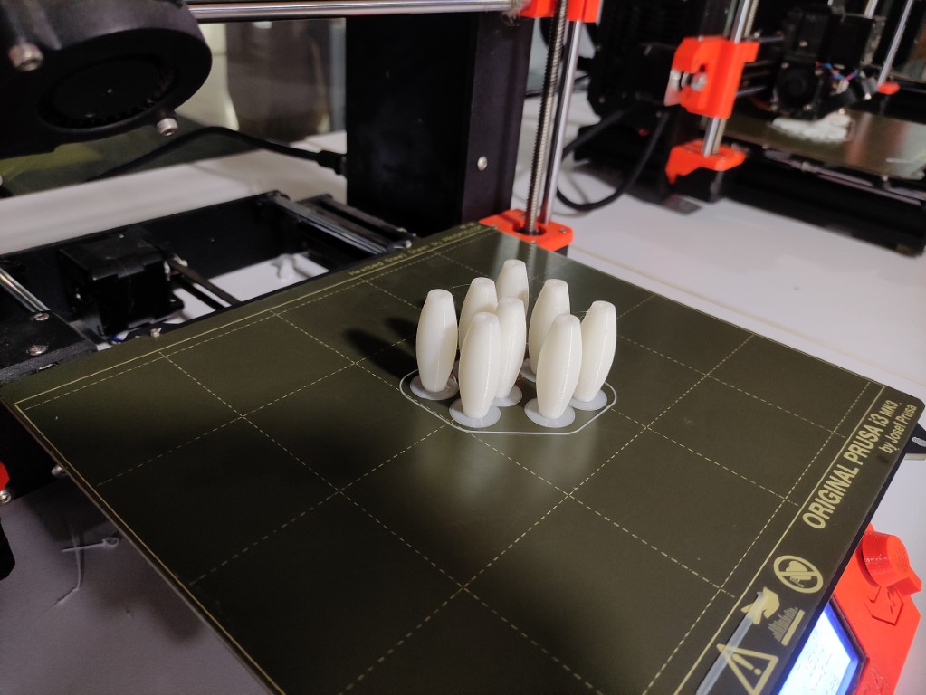
- roller printed from the second design, I gave the brim while 3D printing for not falling it to the side while printing since it is having a vertical shape
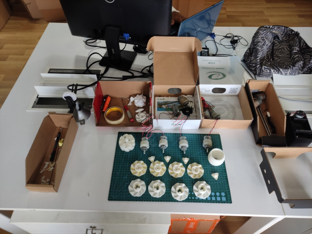
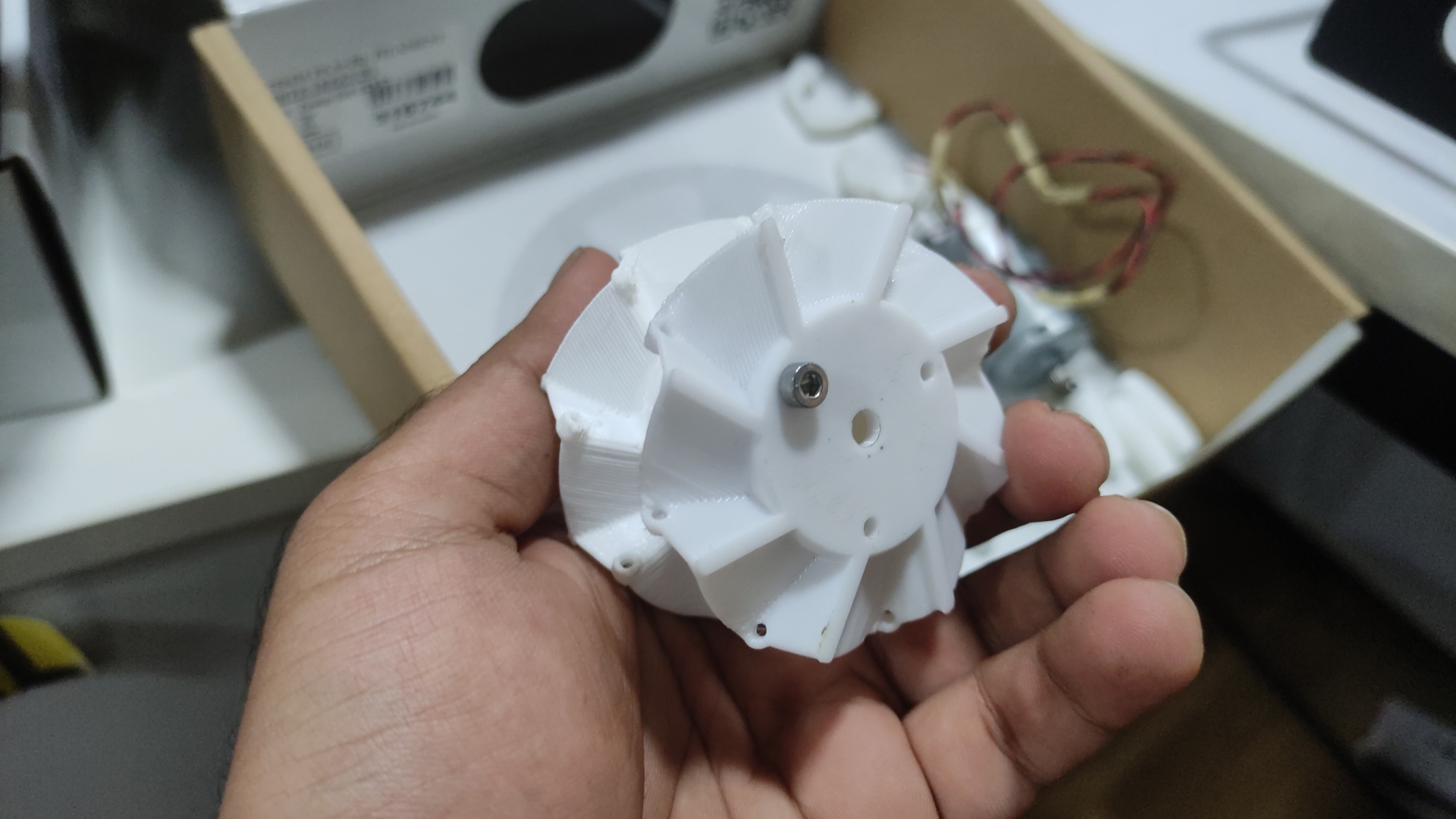
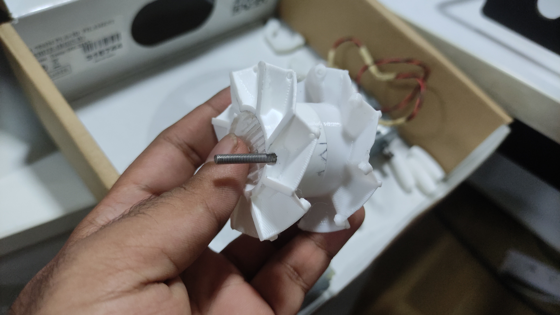
- assembly of the second design
- these are all the components needed to be assembled
- for the rollers to move freely I used a different approach than before, instead of 3d printed notches for placing the rollers I used a steel rod used as a spoke in cycles as a shaft and inserted the rollers into that and attached the shaft to the 3D printed case holes.
- i cut that into uniform lengths using a Dremel
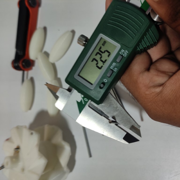
- the steel rod i bought had different sizes i had to verify the dia before cutting using a Vernier
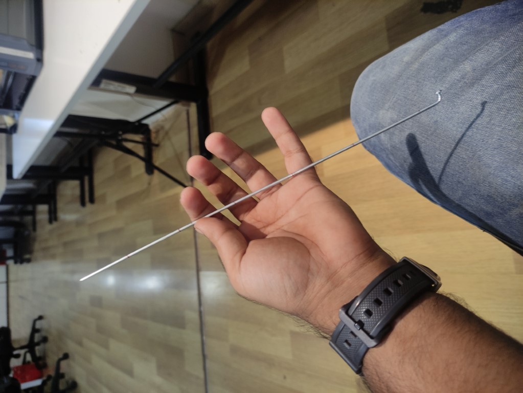
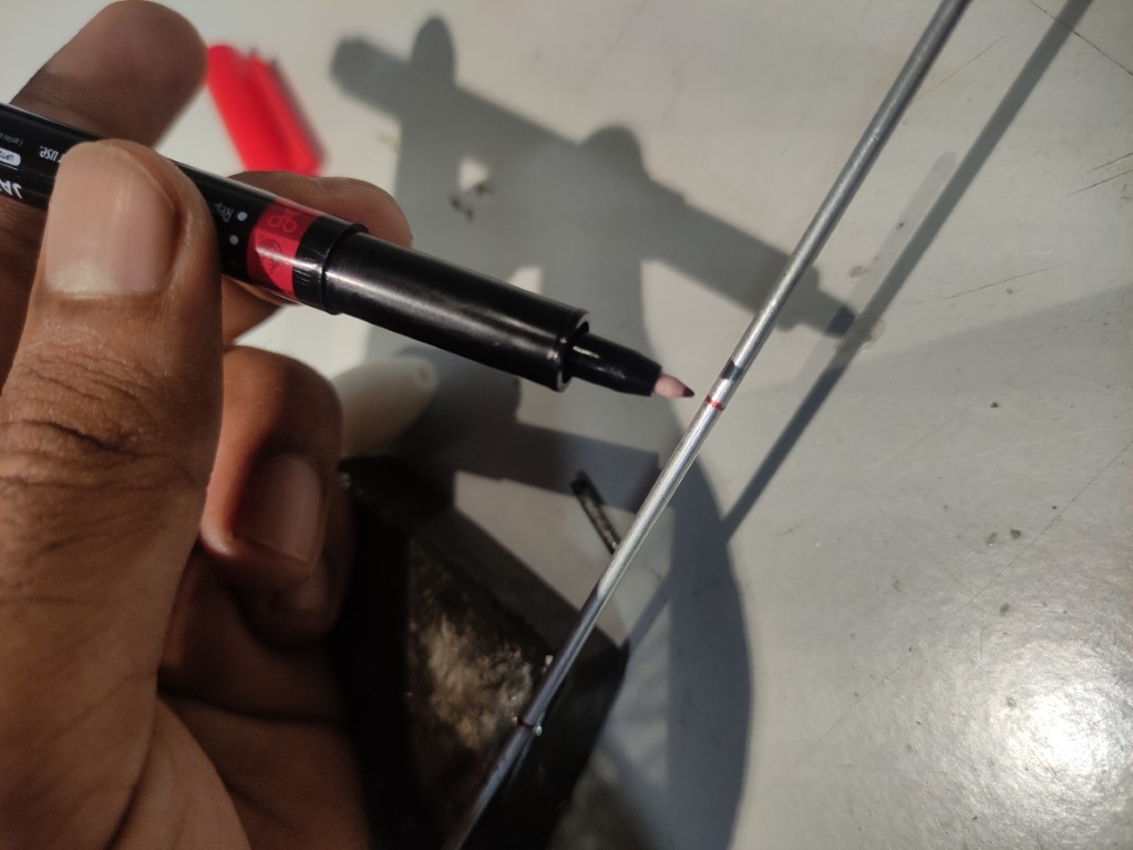
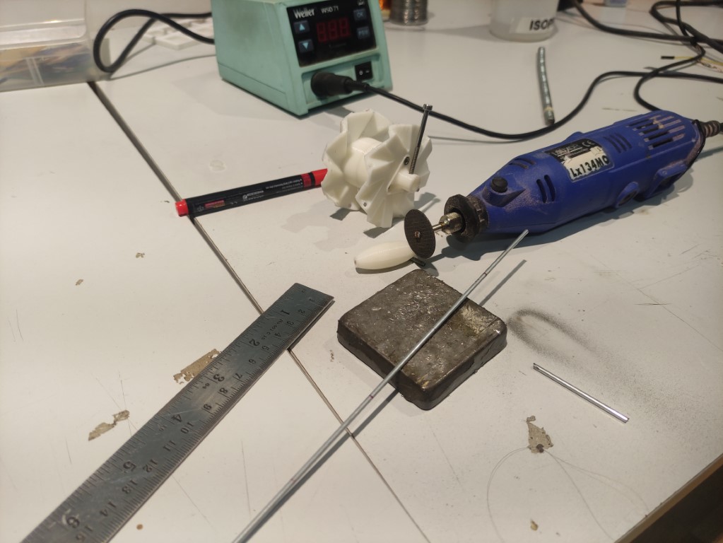
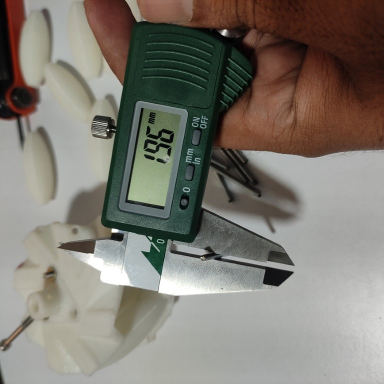
the variations in the dia
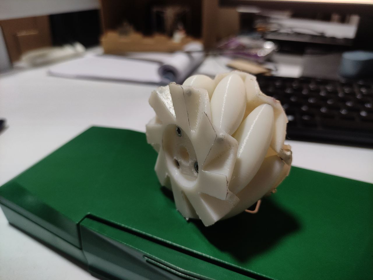
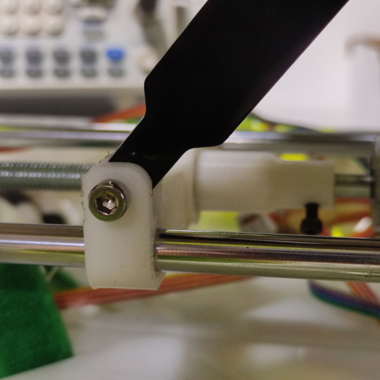
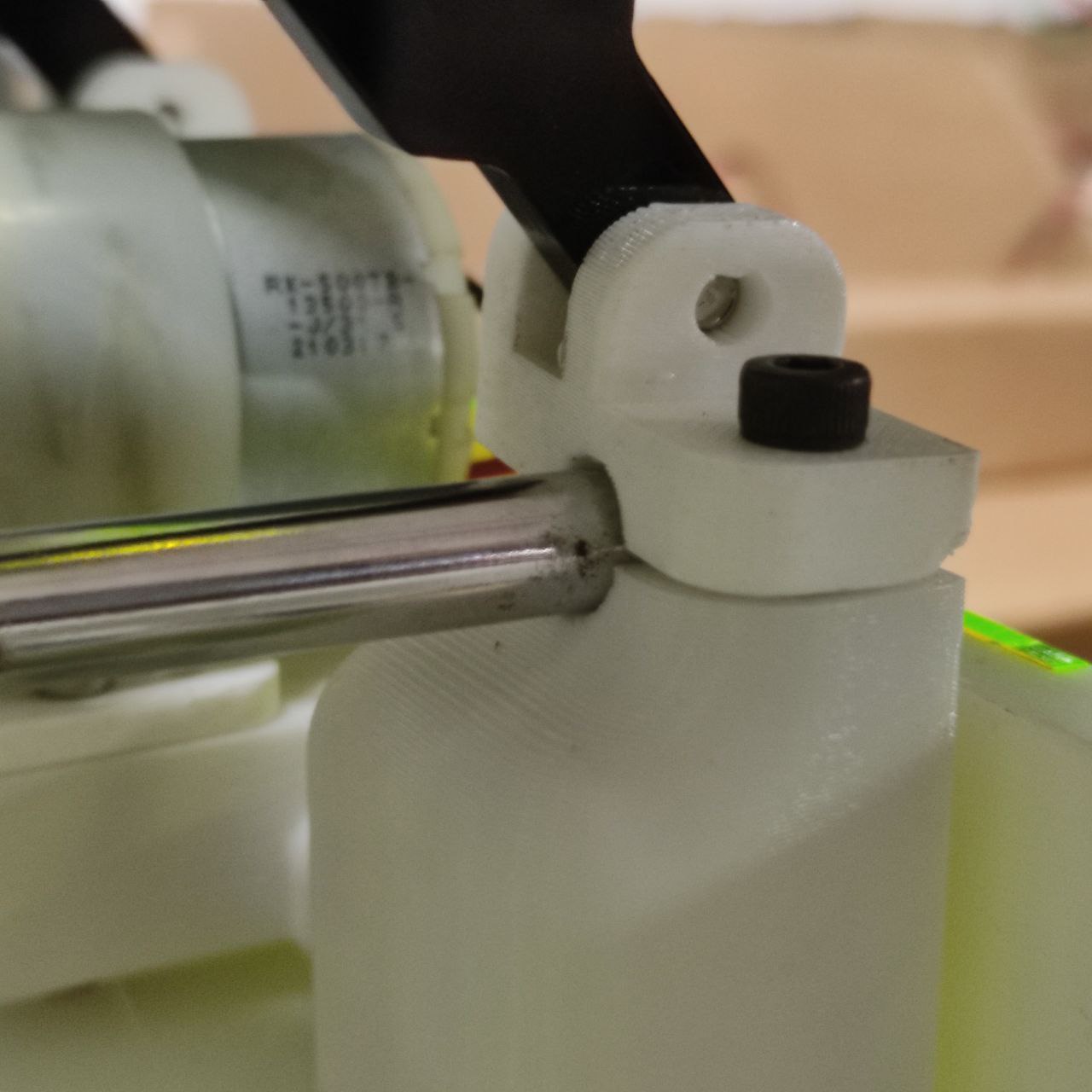
- after placing the shaft rods
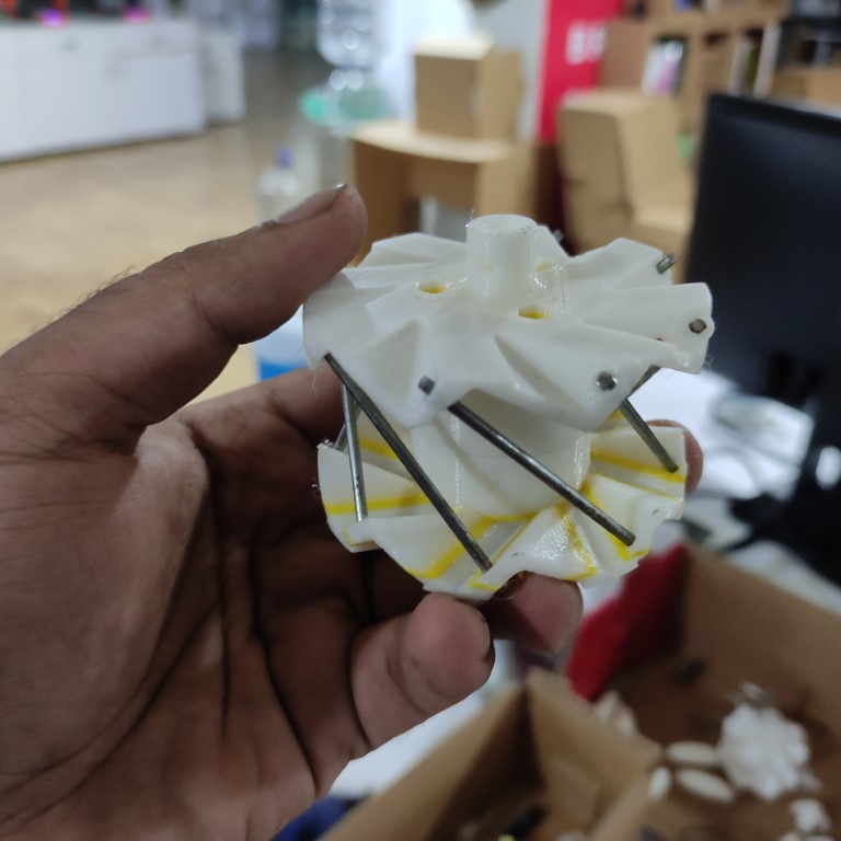
- mecanum wheel after assembly,
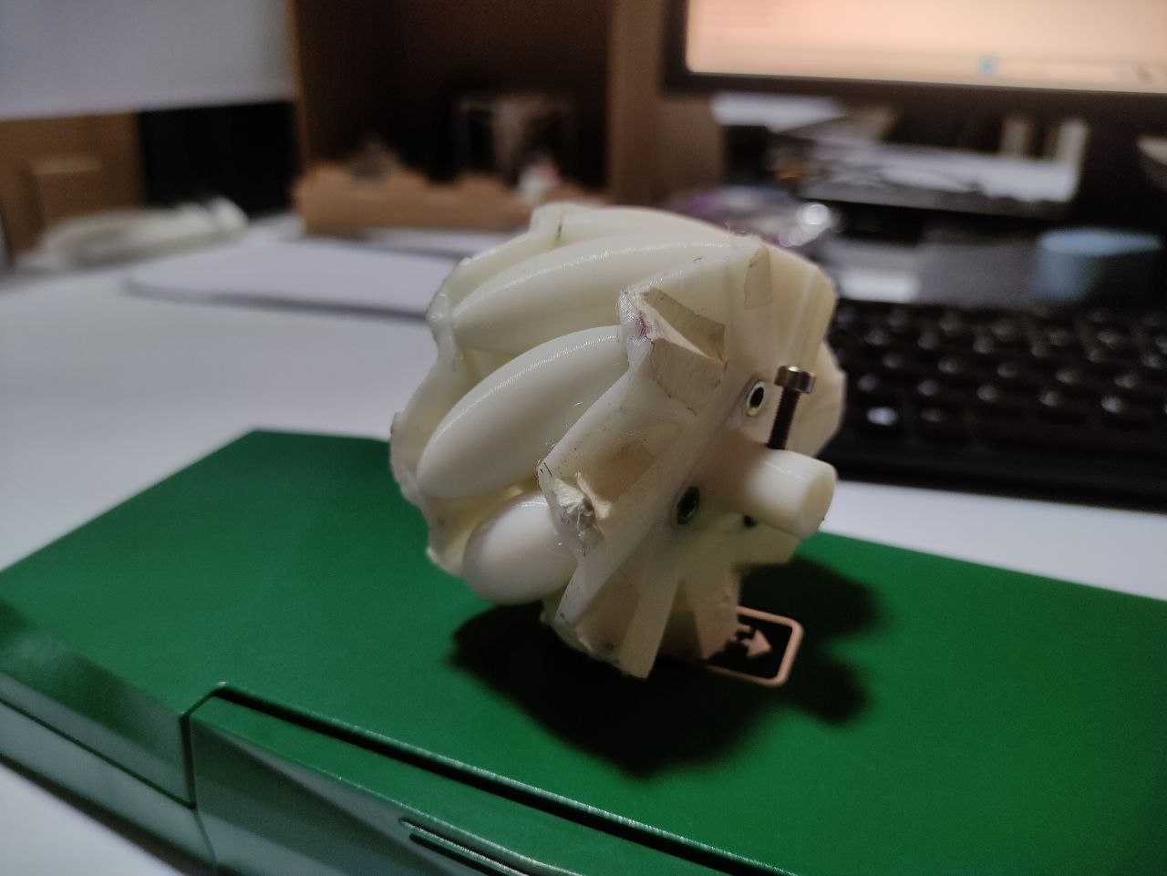
here I used masking tape as a temporary solution instead of cluing the shafts at holes.
- the 3D-printed wheel is rolling smoothly
—>that was a success
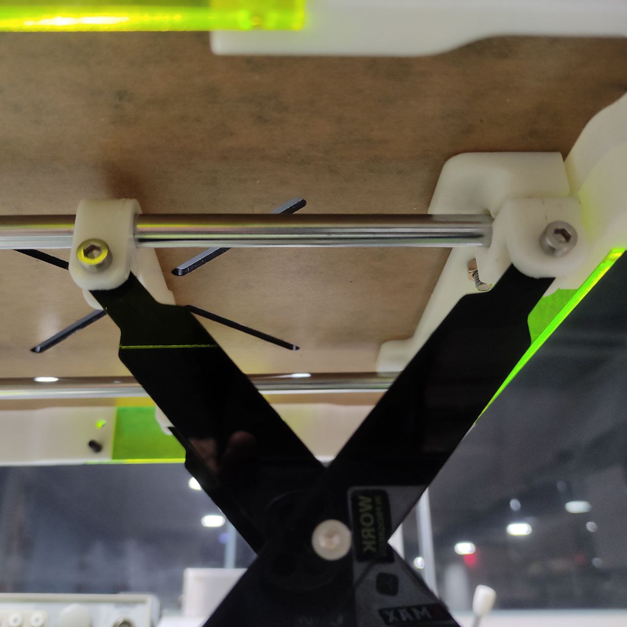
- attaching the wheel to the motor using the 3D-printed coupling
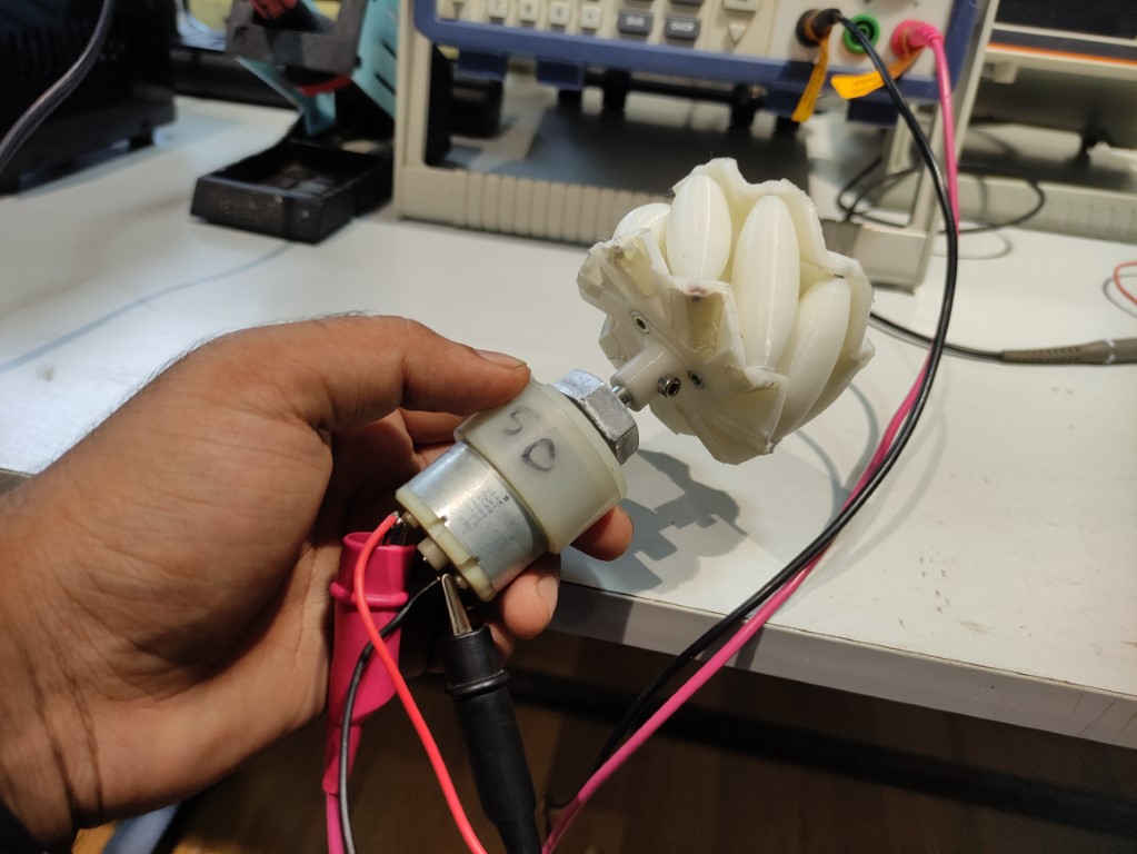
They fitted perfectly, used a 3mm bolt as a pin for the coupling
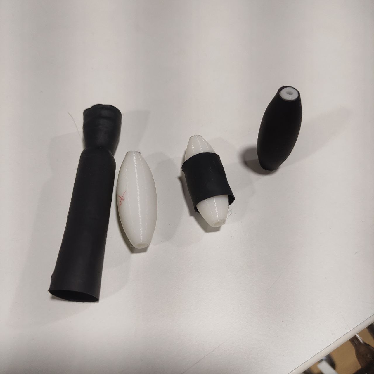
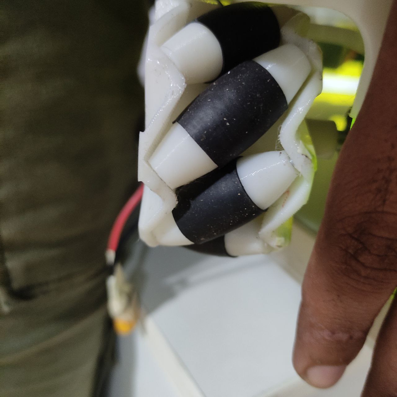
- and now for having a grip on the tires, I used a heat shrink tube,
- inserted the 3D printed rollers inside the heat shrink tube and heated, the rubber wrapped around the roller perfectly.
Phase 2
CAD designing
- The first CAD design was done in the beginning of the project, soon after making the wheel
- this design had to be changed as it will be taking a lot of 3D-printed parts, so to minimize the 3D printing usage I had to optimize the design by using different materials and different ways of machining parts,
- i was also advised by my instructor to utilize as many machines in the lab,
in this design, i have decided to use 3D printing laser cutting, and CNC milling
- Chassis
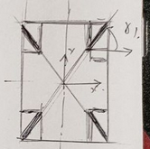
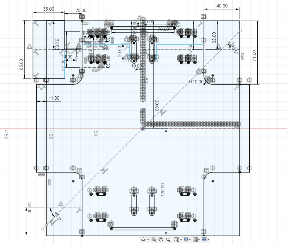
- these are the dimensions based on the calculations of the mecanum wheel
Based on the calculations done and the operational principles of a mecanum wheel, it is expected that the 45-degree angled rollers should meet at the center point. Therefore, when diagonal lines are drawn from each wheel, they should intersect at the midpoint, as designed below.
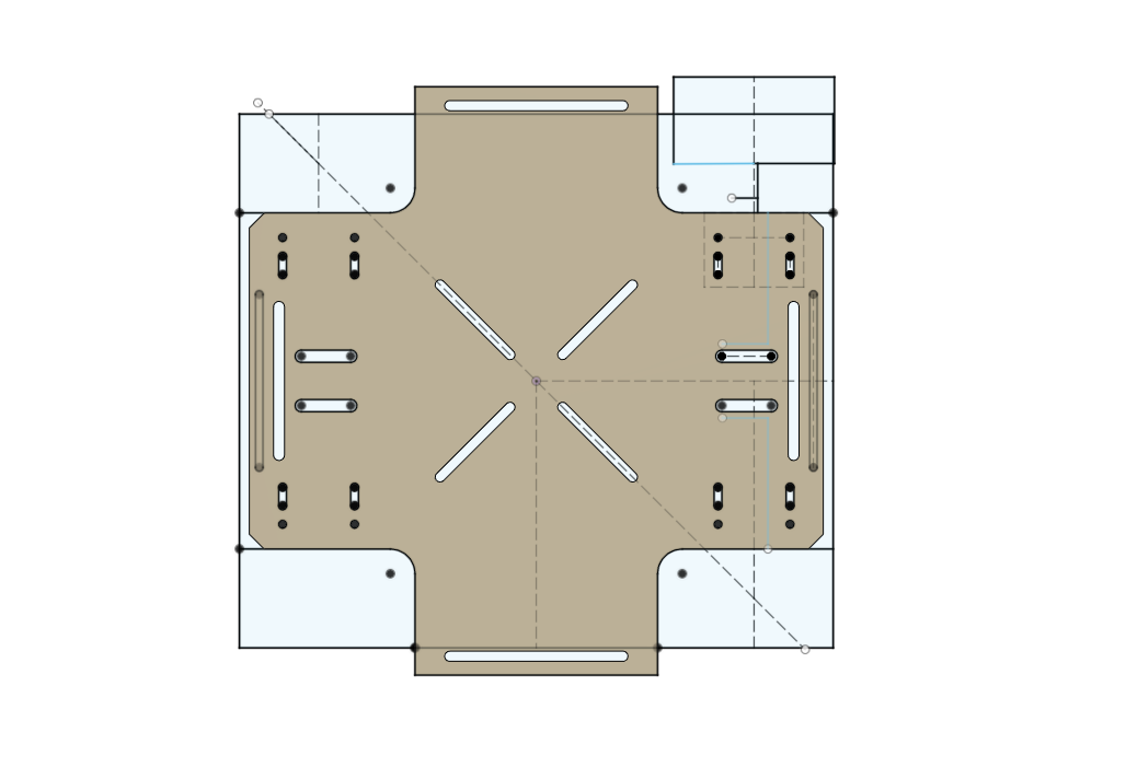
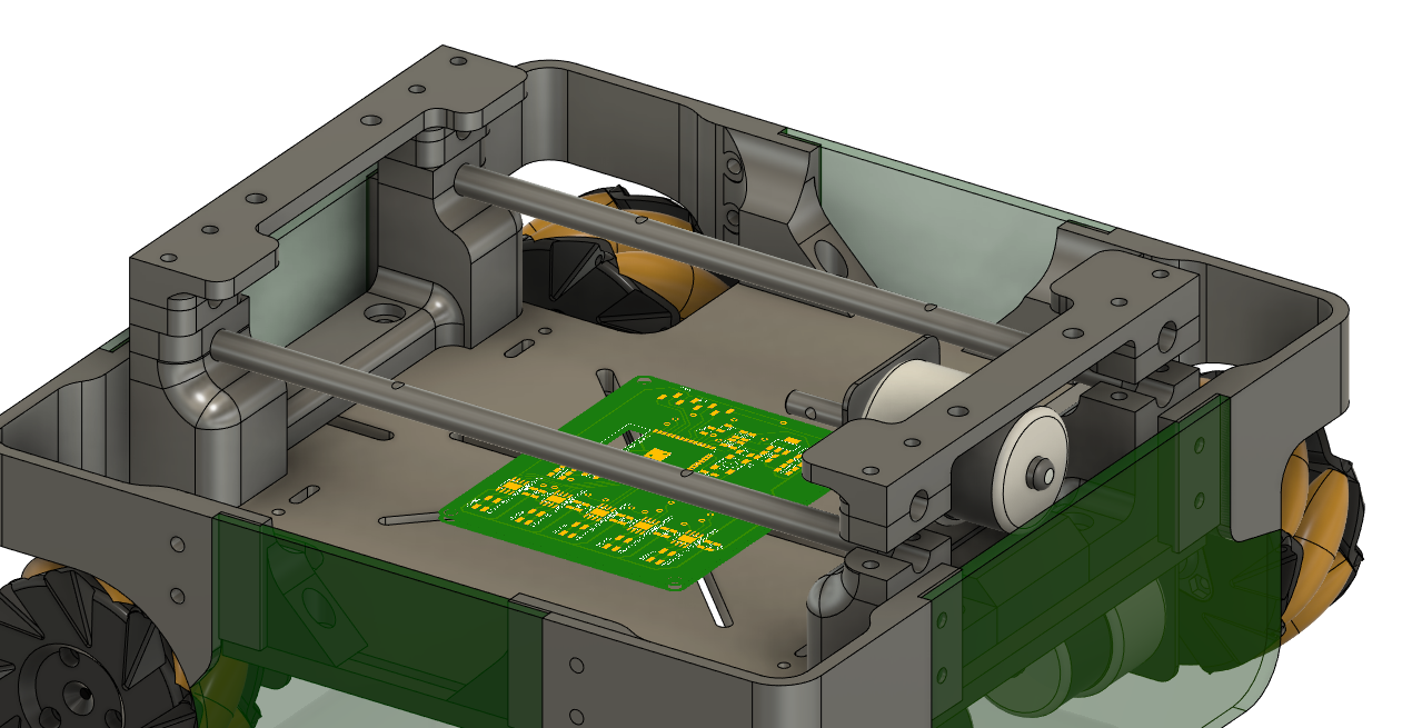
the chassis structure with all the necessary holes for mounting motors, frame, and electronics
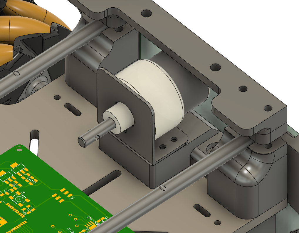
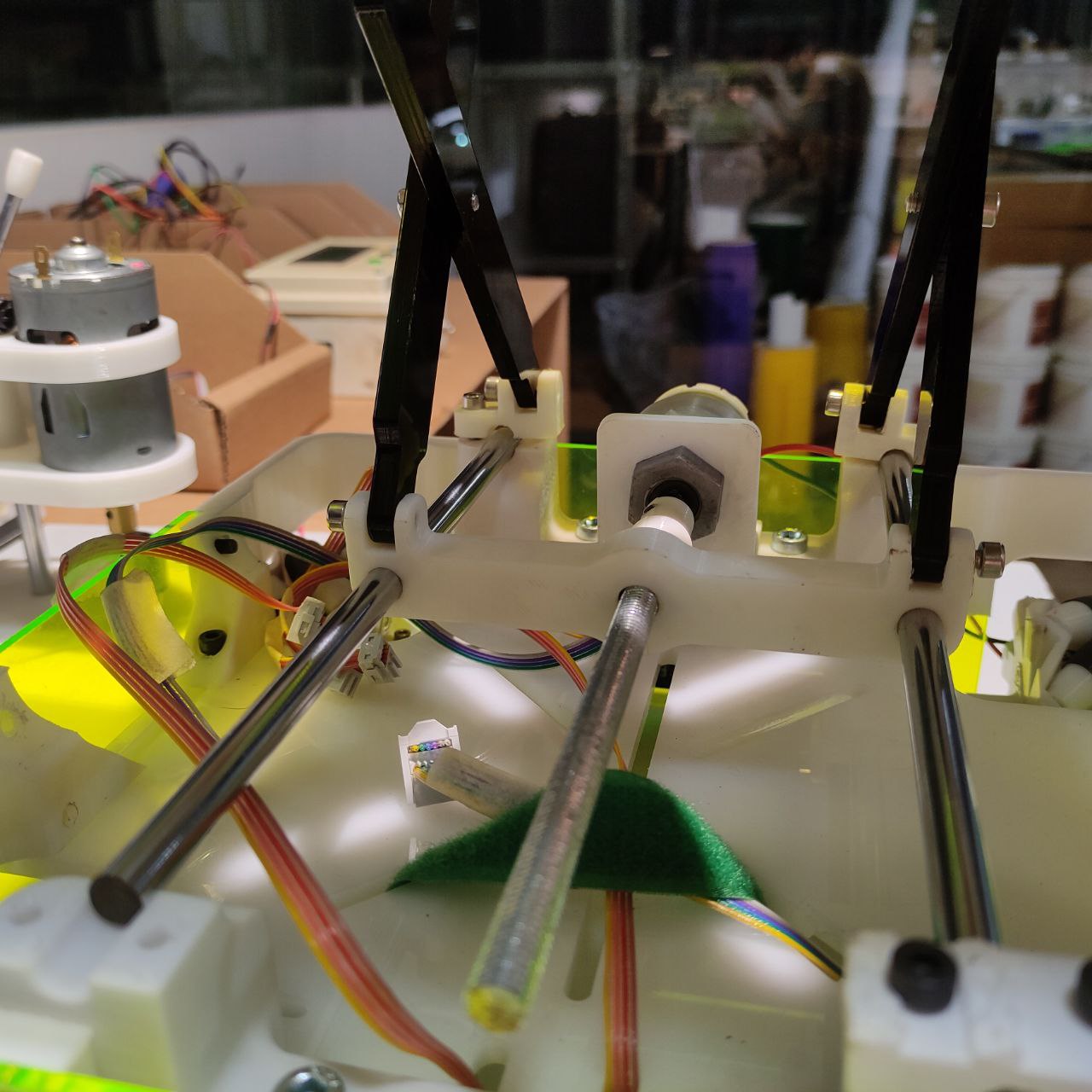
- assembling the motor mounts, DC motors, and wheels
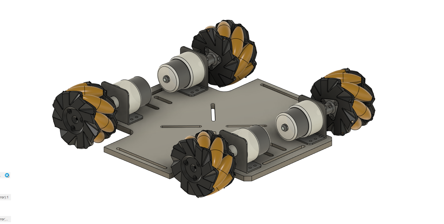
i had to design all these models’ motor mounts, and the DC motors as they were not available online. since it was sourced locally
- Designing the frame
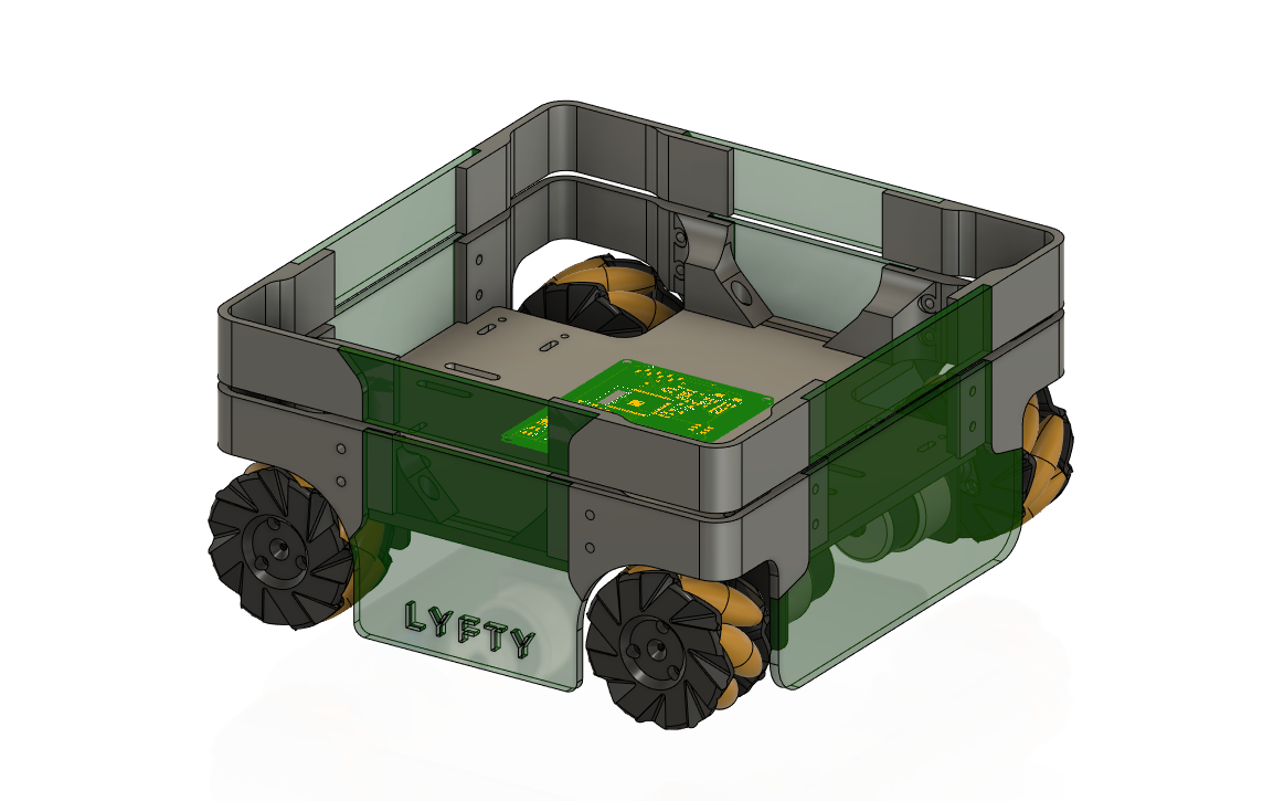
the design of the frame is changed to a hybrid model, where some parts are 3D printed and some are laser cut so there is not much wastage of material, and I could use different materials and machining operations as my tutor instructed
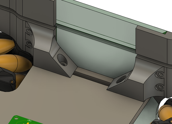
- frame mounting points to the chassis, here we will use a 6mm and 3mm hex bolts
- parts to be 3D printed
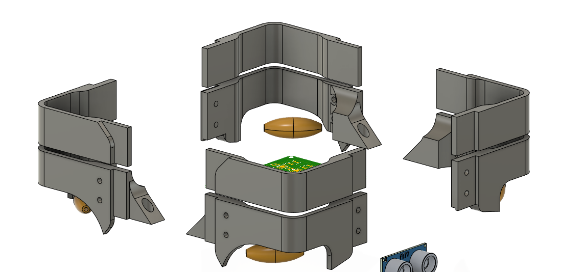
- parts to be later cut
- Lifting mechanism
- placement of Dc motor for lifting
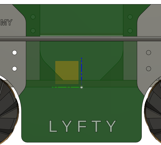
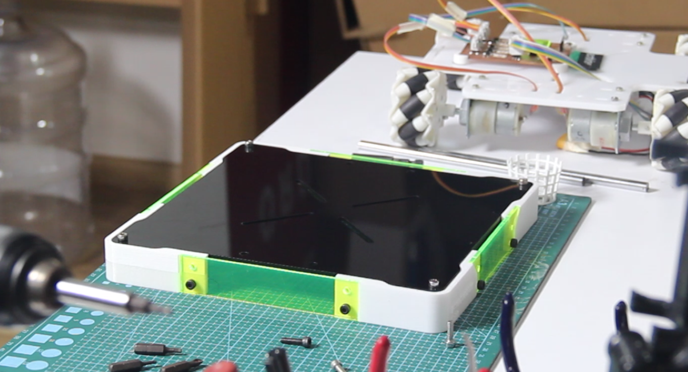
- Top section
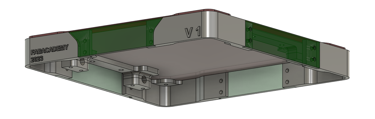
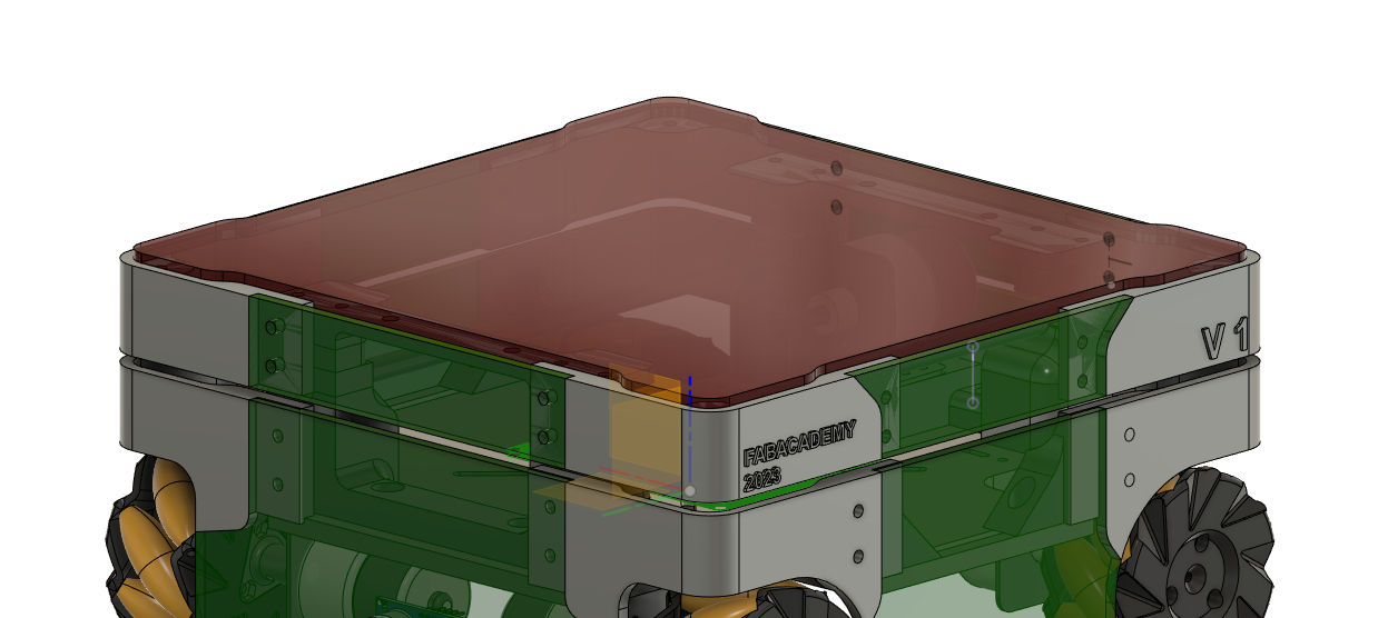
here the top part cover will be laser cut from a 4mm acrylic sheet
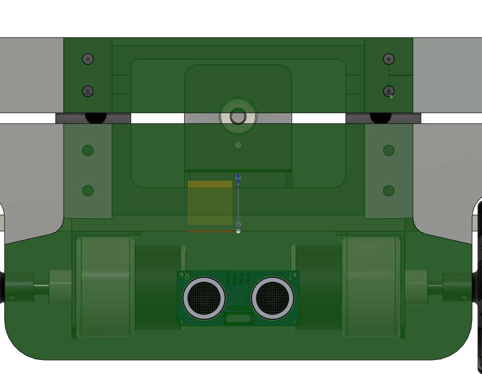
- Mounting for ultra sonic
The CAD design of the scissor lift was lost, because I didn't save the design in Fusion 360 due to the run of presenting the final project. but fortunately, I have videos of the working mechanism that i fabricated, it will be shared in the final phase.
It sounds like the design is almost complete, and any further modifications will only be made after the parts are fabricated. This is because there are many additional constraints in the real world that may impact the final design, which cannot always be found in a CAD environment.
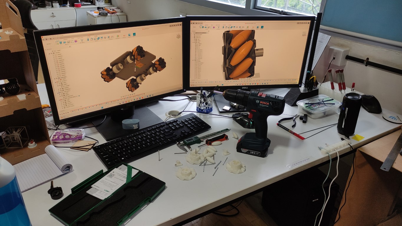
this was my environment while cad designing xd
- 3D design here 👇🏼
Phase 3
Chassis
since the design is almost complete, it is time to fabricate the chassis and assemble the components
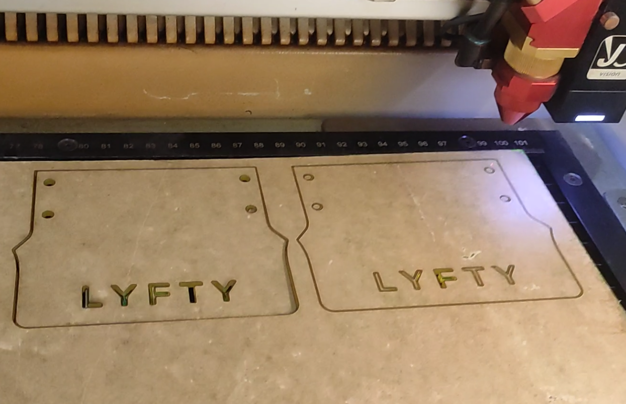
- so first i made the chassis frame out of a 6mm cardboard sheet using the laser cutter, i had to make sure the mounting holes are aligned straight, we had only a few acrylic sheets so a small mistake can stop further progress of this project, and it is also the sustainable way.
laser cutting the chassis on a cardboard “corrugated sheet” sheet
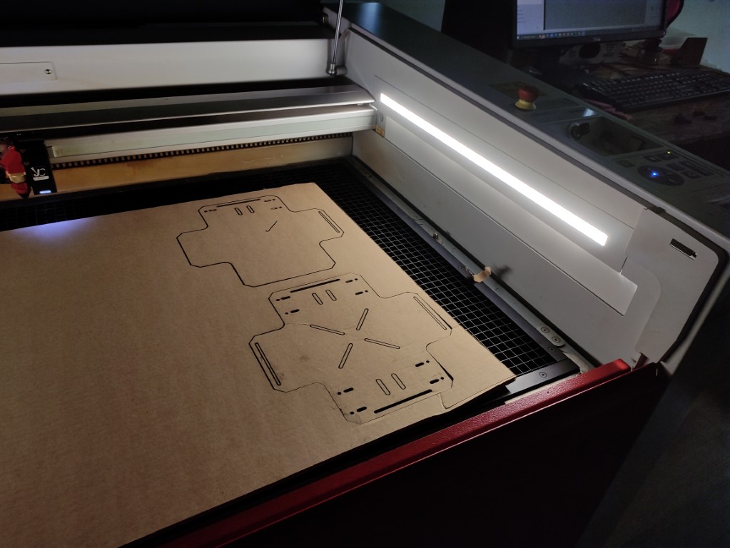
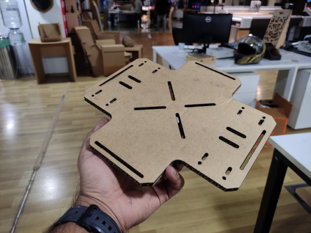
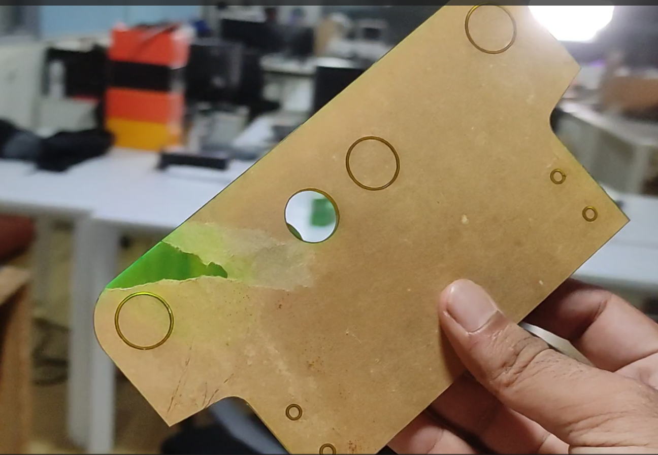
- this was the second cut for the first cut the holes were not aligned properly.
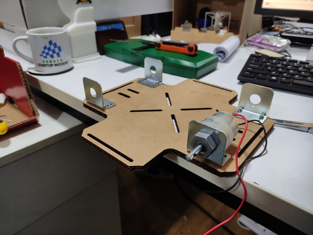
mounted the motors on the cardboard chassis it was more sturdy than I expected.
- the cardboard was torn when i mounted all the wheels and motors, this was purely done out of curiosity.
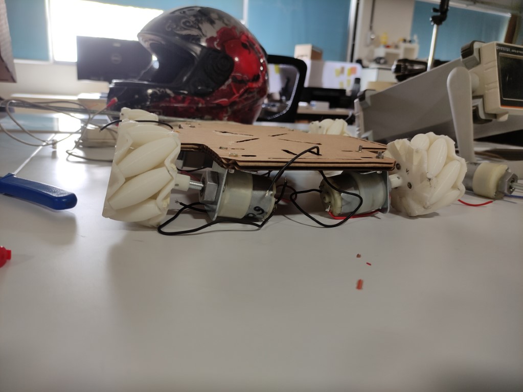
- now i had to cut it from the 6mm white acrylic sheet
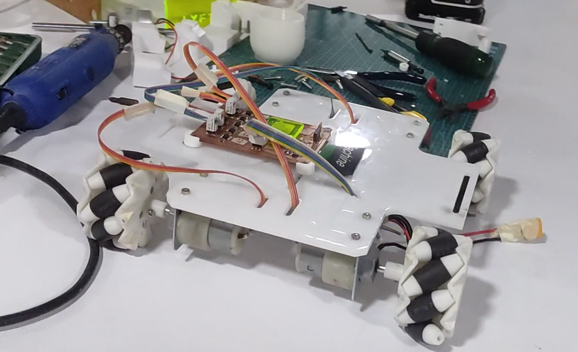
- wheels and PCB mounted on the chassis frame
Phase 4
Electronics
- Requirements for PCB design
-micro-controller using: ESP WROOM 32D
-need to connect an ultrasonic, so design pins for echo and trigger
-there are 5 DC motors four 60 RPM motors and one 150 RPM motor so to control the speed of that we need PWM controllers (PWM stands for Pulse Width Modulation, A PWM controller is a device that uses a pulse-width modulated signal to control power applications).
-Led for indications
- based on these requirements i have designed this PCB
The schematic diagram
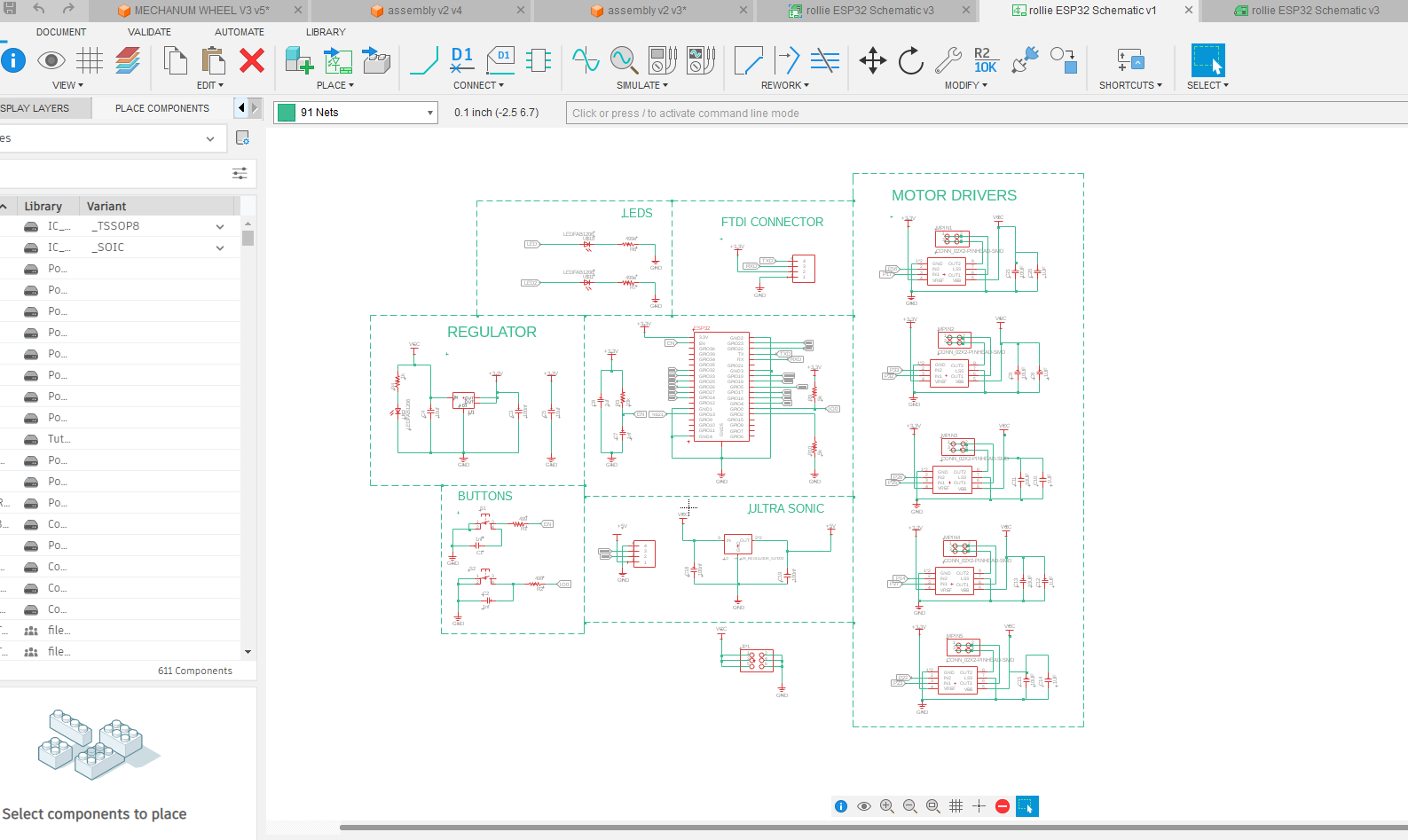
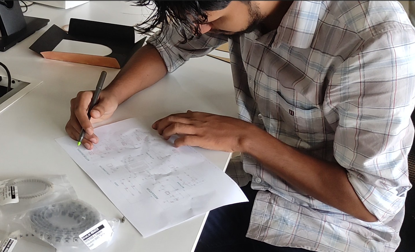
- here is Saheen our academy mentor correcting and fixing my schematic diagram, he is verifying the design before going to PCB design
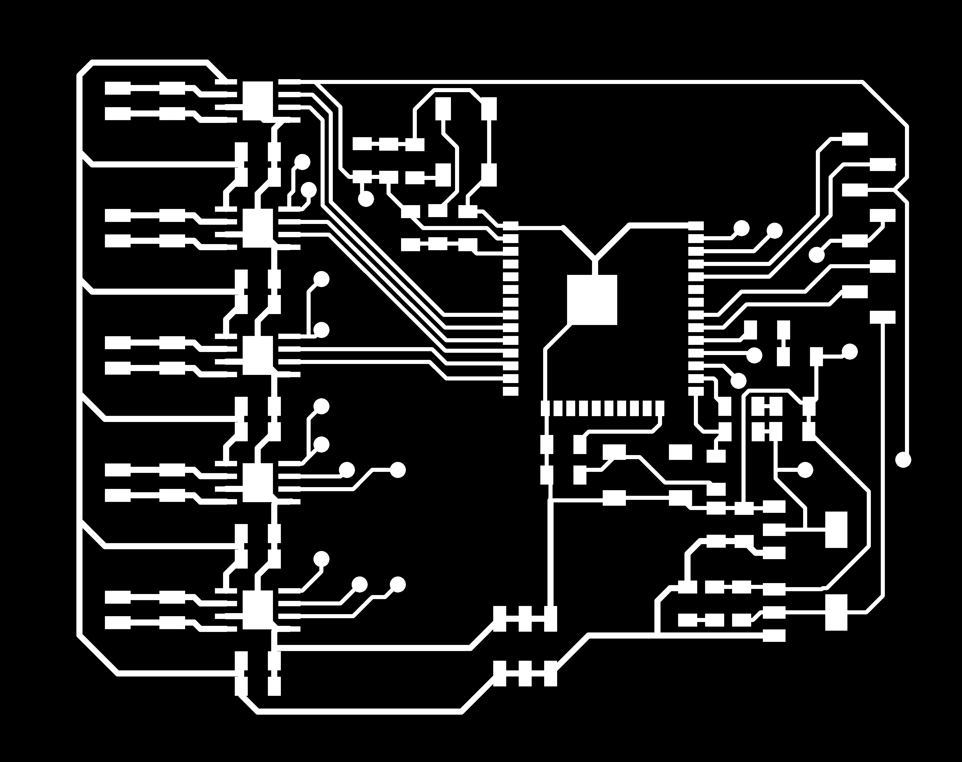
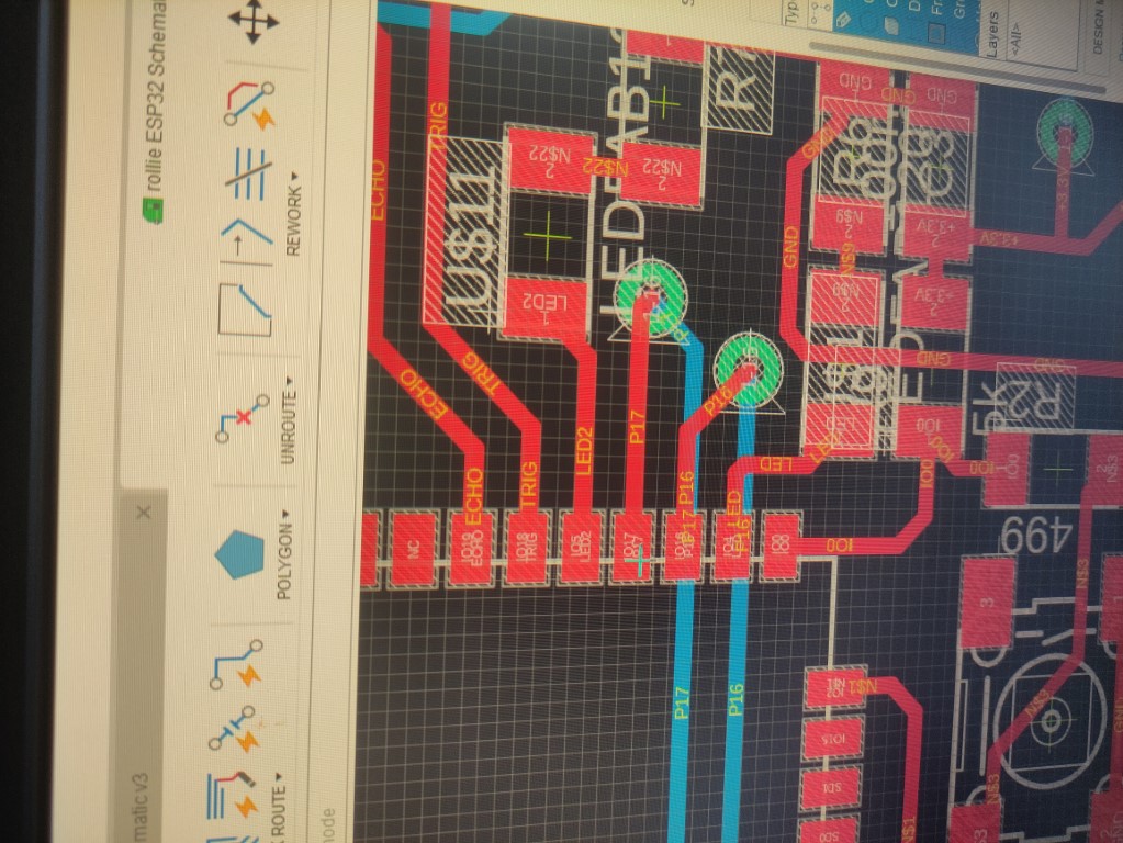
- the PCB design for the above
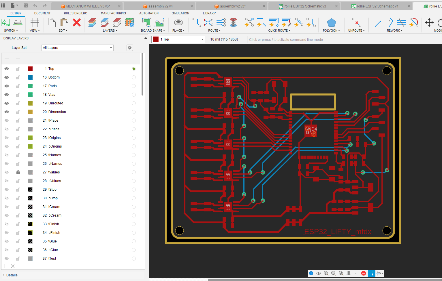
here I had to design and two-layered PCB as there were lots of lines intersecting.
this will be a bit complicated process while milling it
- so we came up with a solution to flip the PCB to get the exact position for milling,
- the idea was to design the outer cut of the PCB in a certain way
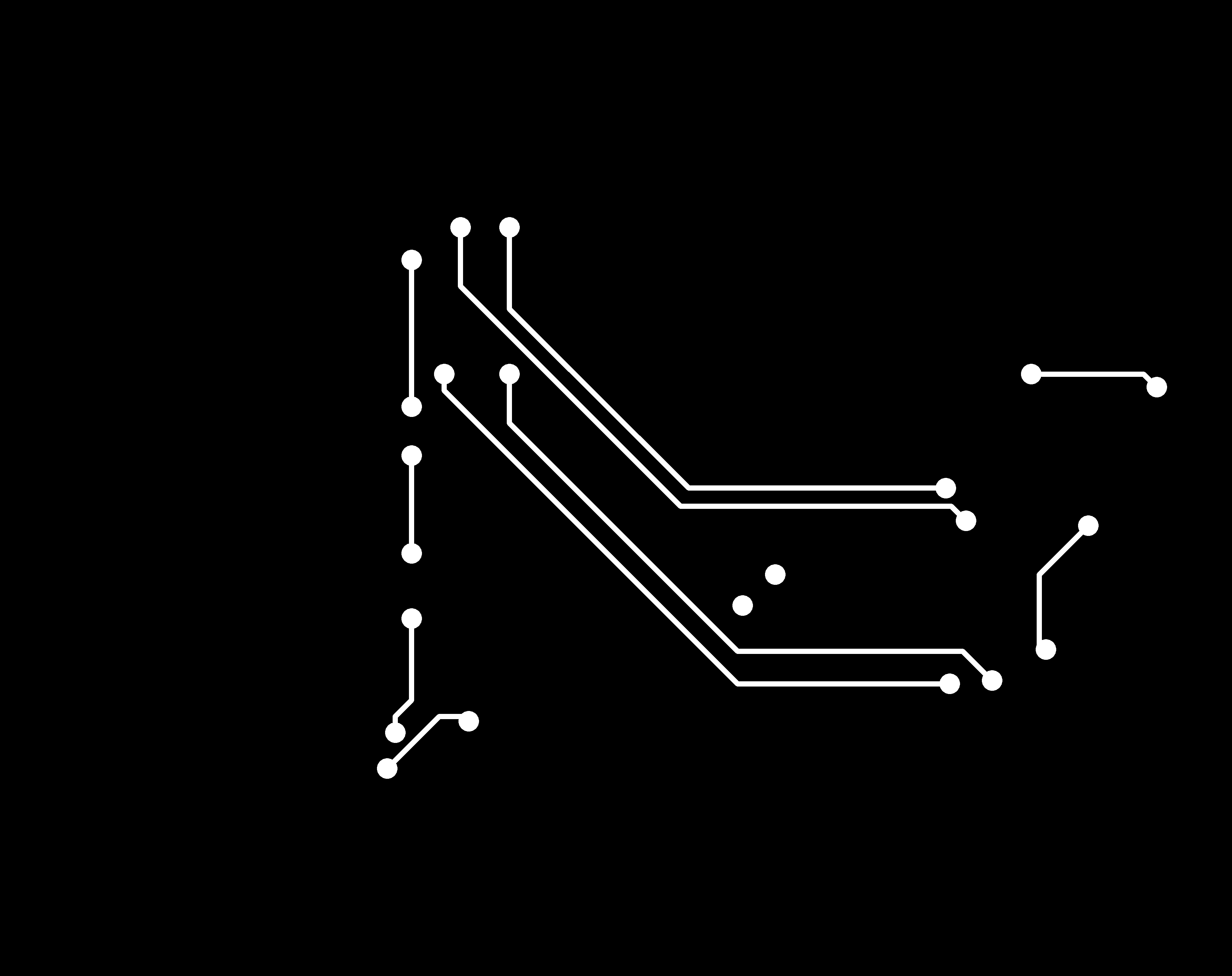
- the trace for the top side
- cuts for the top side
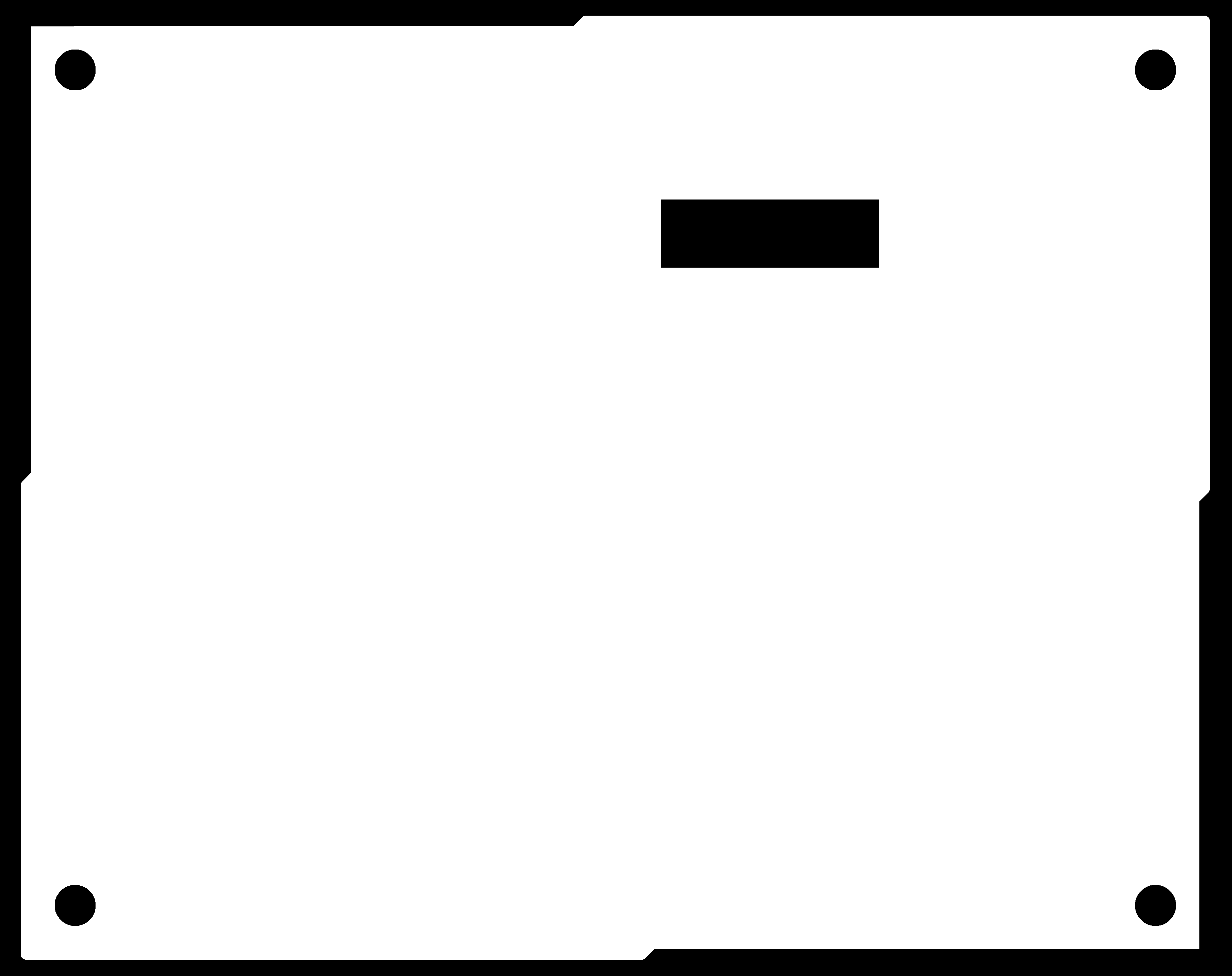
There is a specific groove or cutout shape on the board that has been designed to hold the PCB securely in place when it is flipped over. This ensures that the board remains in the exact position needed for the next step.
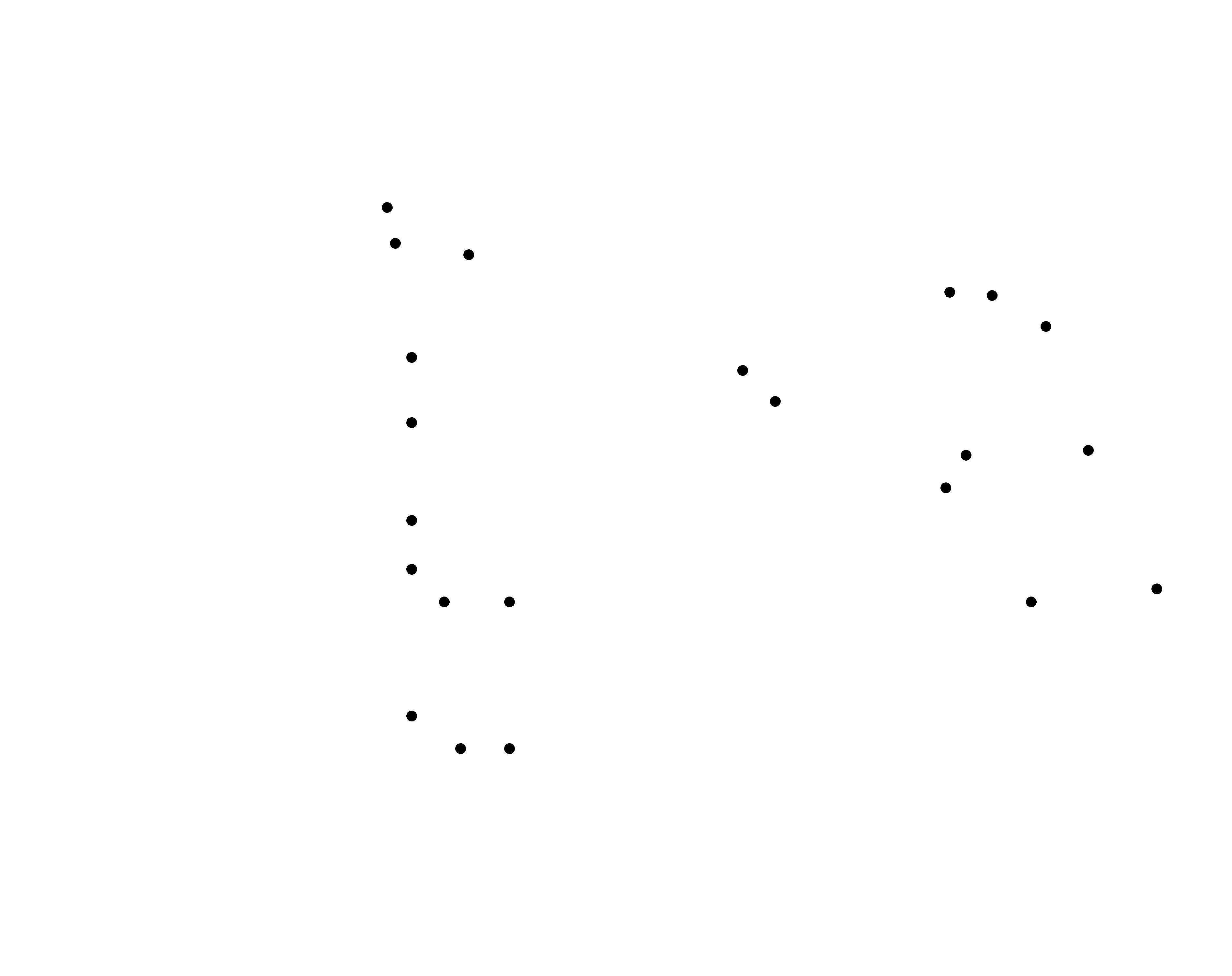
- these are for the backside

- a short montage video of milling the PCB
- here we can see the corner is secured tightly
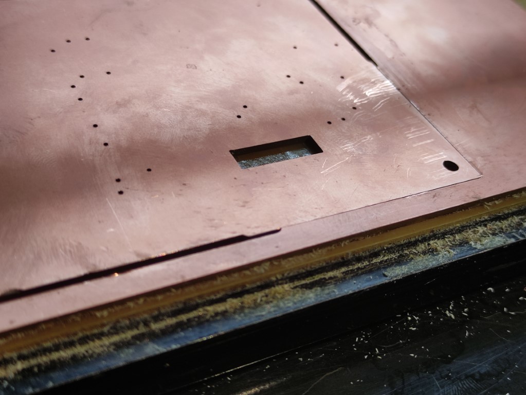
- this is the PCB after milling
.jpg)
- soldering the PCB
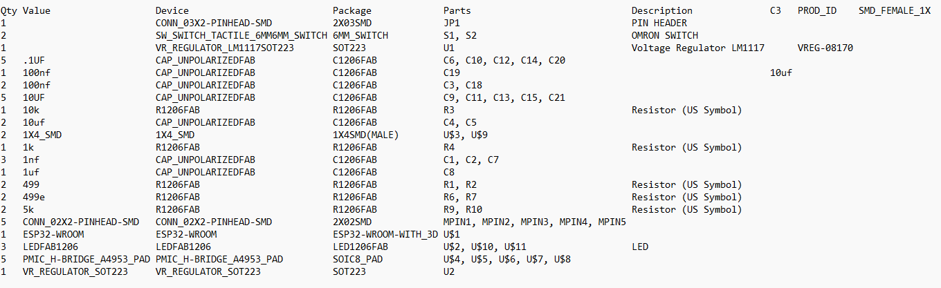
BOM of the PCB
- these are the components needed for soldering
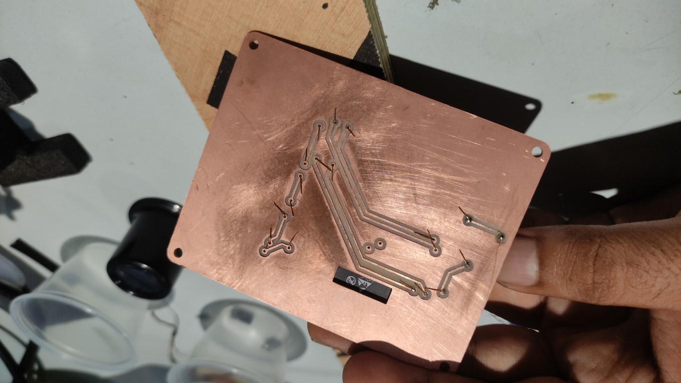
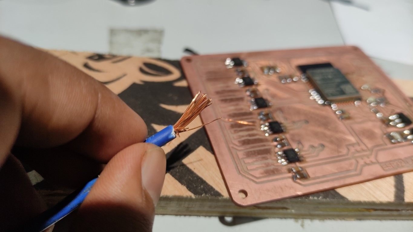
- i used these wires for counting through via holes since we didn't have reverts
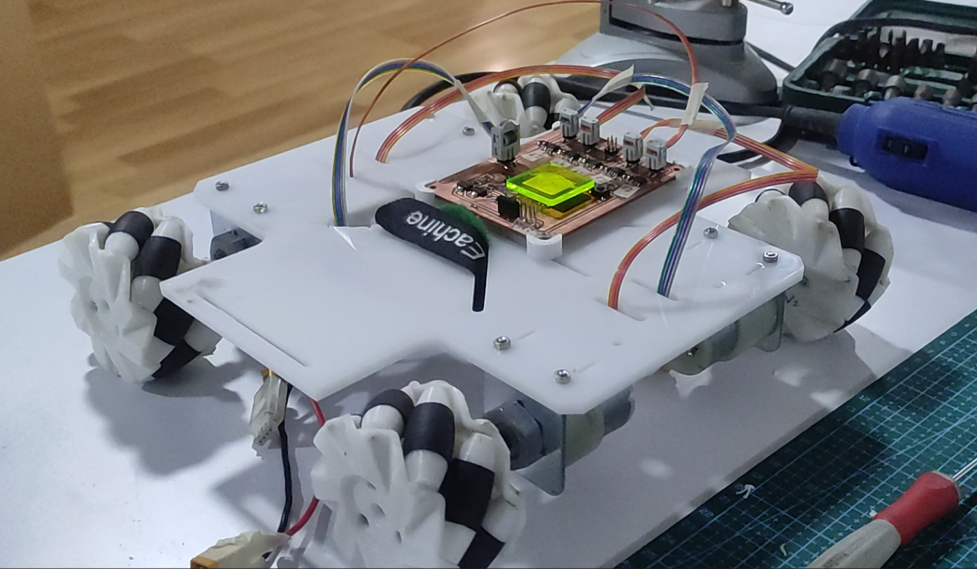
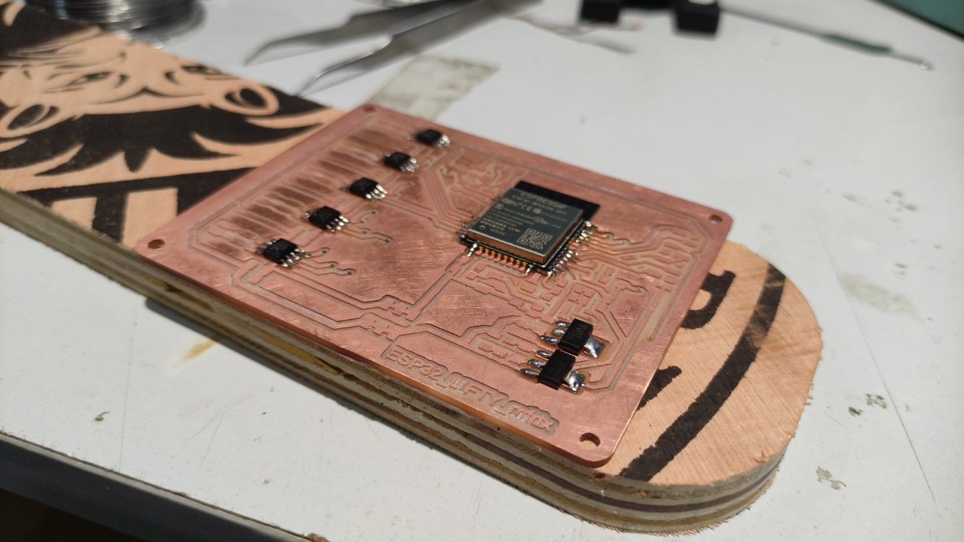
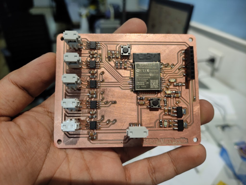
- The PCB after soldering all the components
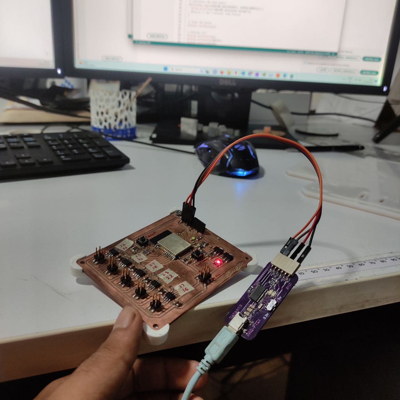
- programmed this PCB with a FTDI programmer using Arduino
the PCB is working, and the internal LED has blinked
- Ran a small code for spinning the DC motor, and just made the DC motor pin High
- ran another code for checking and testing the directions of all the wheels
placed tape on all the motor shafts to see the direction of the motor
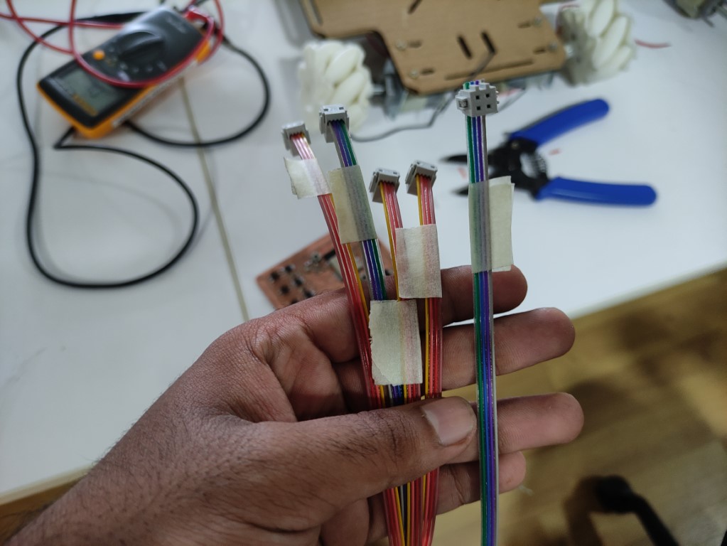
- paced the PCB of the acrylic chassis and wired all the connections to the motor using ribbon cables and labeled it
Phase 5
Frame / Lifting mechanism / Assembly
- laser cutting the frames from 4mm clear acrylic sheet
- 3D printing the corner pieces
- with all these parts, started assembling them
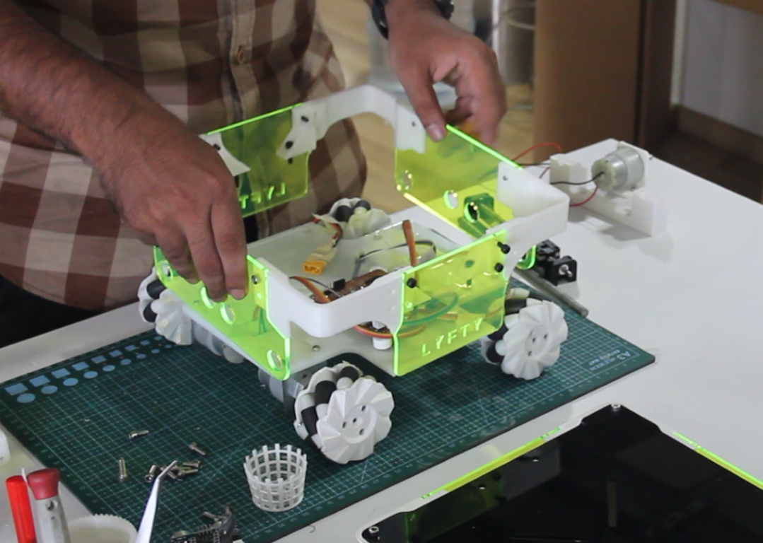
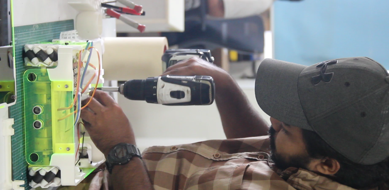
- top section assembly
- bottom section assembly
- Lifting mechanism
Before assembling the scissor lift
- this is the scissor lift mechanism
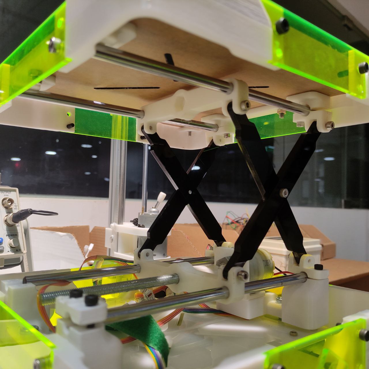
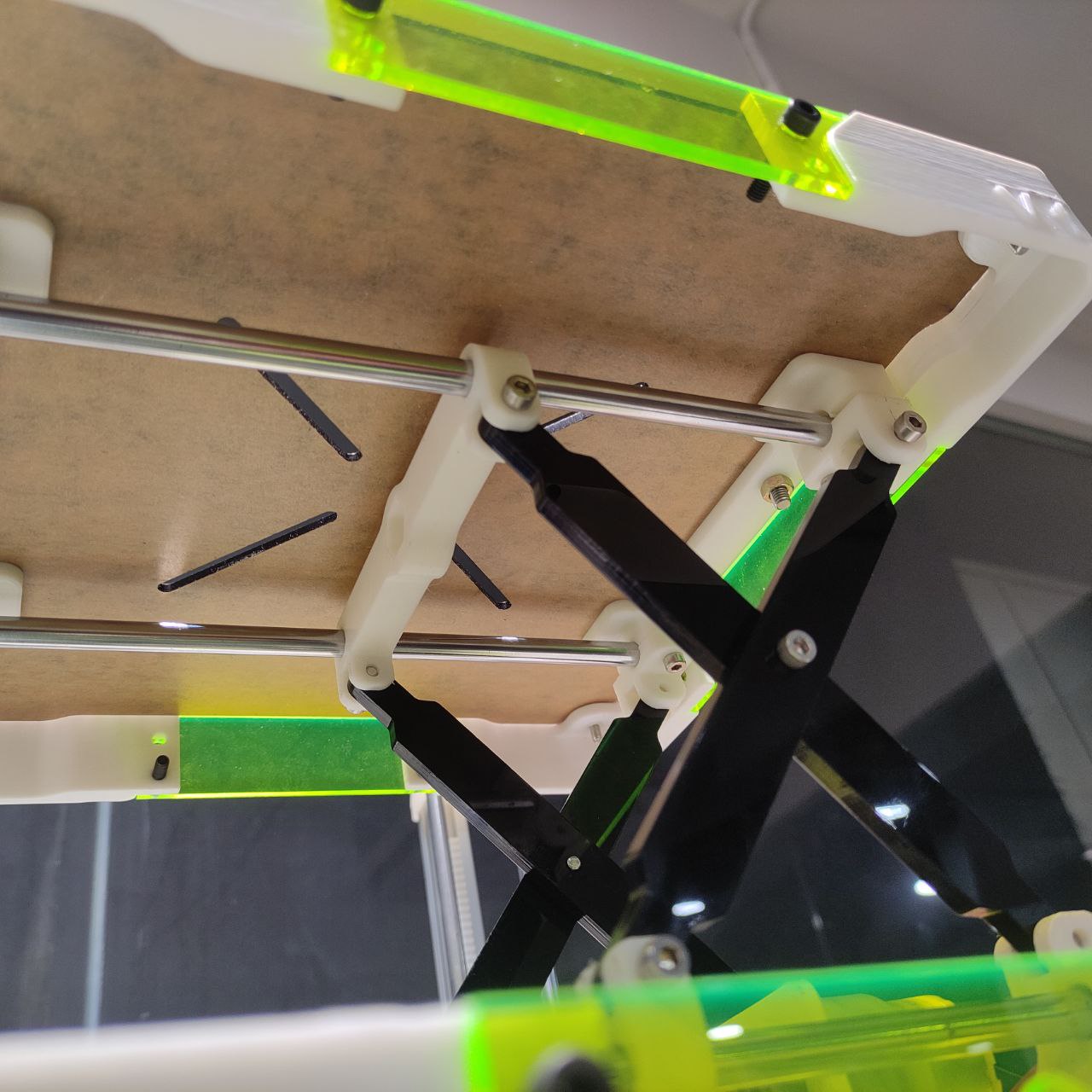
- these are made of laser cut 6mm acrylic sheet
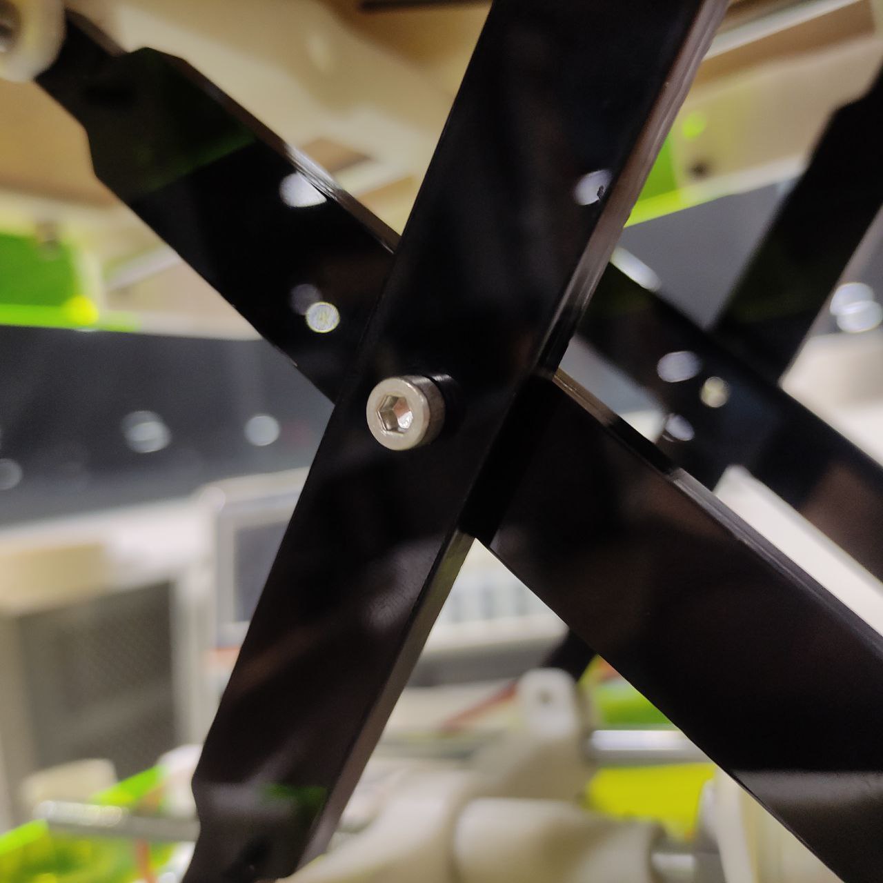
- hinges
- a threaded rod is connected to a dc motor, when this motor turns it pushes the 3D slider forward and backward based on the direction of motor
Phase 6
Programming
- Wrote a program to control all the 5 motors
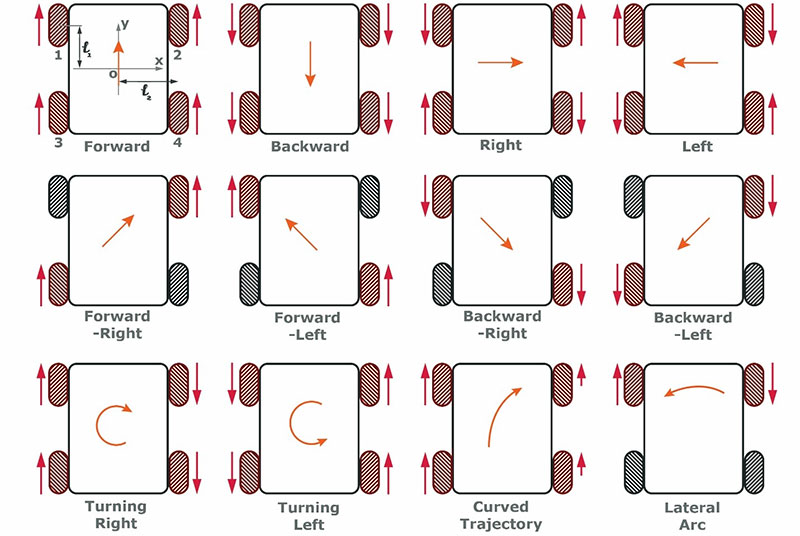
- so before that, I had to map the movements of the mecanum wheel,
- since there is no steering of the wheels, we can only control the direction of the bot by changing the turning the direction of the wheels in a certain way
- this is a chart to understand in which direction the wheel has to be moved for different movements of the vehicle
- as a first step, I named the motor driver pins, and ultra sonic sensor
// Configuration


//PINs --------------------------------------
// Motor Driver Pins-----------

// Left Front
#define LEFT_FRONT_FW 32
#define LEFT_FRONT_BW 33

// Left Back
#define LEFT_BACK_FW 25
#define LEFT_BACK_BW 26

// Right Front
#define RIGHT_FRONT_FW 27
#define RIGHT_FRONT_BW 16

// Right Back
#define RIGHT_BACK_FW 23
#define RIGHT_BACK_BW 22

// Lift
#define LIFT_UP 17
#define LIFT_DOWN 16


// Ultrasonic Sensors Pins ---
#define US_TRIGGER 18
#define US_ECHO 19

// LED Pins
#define LED_GREEN 5
#define LED_YELLOW 4


// Movements

#define FRONT 1
#define BACK 2
#define LEFT 3
#define RIGHT 4
#define CW 5
#define CCW 6
#define STOP 7

#define UP 8
#define DOWN 9
- then gave definitions for each motor movement and ultra-sonic sensors triggers
// Initialise Motor

void init_IO() {
  pinMode(LEFT_FRONT_FW, OUTPUT);
  pinMode(LEFT_FRONT_BW, OUTPUT);

  pinMode(LEFT_BACK_FW, OUTPUT);
  pinMode(LEFT_BACK_BW, OUTPUT);

  pinMode(RIGHT_FRONT_FW, OUTPUT);
  pinMode(RIGHT_FRONT_BW, OUTPUT);

  pinMode(RIGHT_BACK_FW, OUTPUT);
  pinMode(RIGHT_BACK_BW, OUTPUT);

  pinMode(LIFT_UP, OUTPUT);
  pinMode(LIFT_DOWN, OUTPUT);

  // Ultrasonic Sensors

  pinMode(US_TRIGGER, OUTPUT);
  pinMode(US_ECHO, INPUT);
}

void int_sequence() {
  pinMode(LED_GREEN, OUTPUT);
  pinMode(LED_YELLOW, OUTPUT);

  for (int i = 0; i < 5; i++) {
    digitalWrite(LED_GREEN, HIGH);
    digitalWrite(LED_YELLOW, HIGH);
    delay(300);
    digitalWrite(LED_GREEN, LOW);
    digitalWrite(LED_YELLOW, LOW);
    delay(300);
  }
  digitalWrite(LED_GREEN, HIGH);
}
- code for different movements based on the above chart
Code ←-click here to drop
void move(int direction) {
  switch (direction) {
      //---------FRONT---------------------
    case FRONT:
      digitalWrite(LEFT_FRONT_FW, HIGH);
      digitalWrite(LEFT_FRONT_BW, LOW);

      digitalWrite(LEFT_BACK_FW, HIGH);
      digitalWrite(LEFT_BACK_BW, LOW);

      digitalWrite(RIGHT_FRONT_FW, HIGH);
      digitalWrite(RIGHT_FRONT_BW, LOW);

      digitalWrite(RIGHT_BACK_FW, HIGH);
      digitalWrite(RIGHT_BACK_BW, LOW);
      break;
      //---------BACK---------------------
    case BACK:
      digitalWrite(LEFT_FRONT_FW, LOW);
      digitalWrite(LEFT_FRONT_BW, HIGH);

      digitalWrite(LEFT_BACK_FW, LOW);
      digitalWrite(LEFT_BACK_BW, HIGH);

      digitalWrite(RIGHT_FRONT_FW, LOW);
      digitalWrite(RIGHT_FRONT_BW, HIGH);

      digitalWrite(RIGHT_BACK_FW, LOW);
      digitalWrite(RIGHT_BACK_BW, HIGH);
      break;

      //---------LEFT---------------------
    case LEFT:
      digitalWrite(LEFT_FRONT_FW, LOW);
      digitalWrite(LEFT_FRONT_BW, HIGH);

      digitalWrite(LEFT_BACK_FW, HIGH);
      digitalWrite(LEFT_BACK_BW, LOW);

      digitalWrite(RIGHT_FRONT_FW, HIGH);
      digitalWrite(RIGHT_FRONT_BW, LOW);

      digitalWrite(RIGHT_BACK_FW, LOW);
      digitalWrite(RIGHT_BACK_BW, HIGH);

      break;

      //---------RIGHT---------------------
    case RIGHT:

      digitalWrite(LEFT_FRONT_FW, HIGH);
      digitalWrite(LEFT_FRONT_BW, LOW);

      digitalWrite(LEFT_BACK_FW, LOW);
      digitalWrite(LEFT_BACK_BW, HIGH);

      digitalWrite(RIGHT_FRONT_FW, LOW);
      digitalWrite(RIGHT_FRONT_BW, HIGH);

      digitalWrite(RIGHT_BACK_FW, HIGH);
      digitalWrite(RIGHT_BACK_BW, LOW);

      break;

      //---------CW---------------------
    case CW:
      digitalWrite(LEFT_FRONT_FW, HIGH);
      digitalWrite(LEFT_FRONT_BW, LOW);

      digitalWrite(LEFT_BACK_FW, HIGH);
      digitalWrite(LEFT_BACK_BW, LOW);

      digitalWrite(RIGHT_FRONT_FW, LOW);
      digitalWrite(RIGHT_FRONT_BW, HIGH);

      digitalWrite(RIGHT_BACK_FW, LOW);
      digitalWrite(RIGHT_BACK_BW, HIGH);

      break;

      //---------CCW---------------------
    case CCW:

      digitalWrite(LEFT_FRONT_FW, LOW);
      digitalWrite(LEFT_FRONT_BW, HIGH);

      digitalWrite(LEFT_BACK_FW, LOW);
      digitalWrite(LEFT_BACK_BW, HIGH);

      digitalWrite(RIGHT_FRONT_FW, HIGH);
      digitalWrite(RIGHT_FRONT_BW, LOW);

      digitalWrite(RIGHT_BACK_FW, HIGH);
      digitalWrite(RIGHT_BACK_BW, LOW);

      break;

      //---------STOP---------------------
    case STOP:
      digitalWrite(LEFT_FRONT_FW, LOW);
      digitalWrite(LEFT_FRONT_BW, LOW);

      digitalWrite(LEFT_BACK_FW, LOW);
      digitalWrite(LEFT_BACK_BW, LOW);

      digitalWrite(RIGHT_FRONT_FW, LOW);
      digitalWrite(RIGHT_FRONT_BW, LOW);

      digitalWrite(RIGHT_BACK_FW, LOW);
      digitalWrite(RIGHT_BACK_BW, LOW);
      break;

      //------------------------------
    default:
      digitalWrite(LEFT_FRONT_FW, LOW);
      digitalWrite(LEFT_FRONT_BW, LOW);

      digitalWrite(LEFT_BACK_FW, LOW);
      digitalWrite(LEFT_BACK_BW, LOW);

      digitalWrite(RIGHT_FRONT_FW, LOW);
      digitalWrite(RIGHT_FRONT_BW, LOW);

      digitalWrite(RIGHT_BACK_FW, LOW);
      digitalWrite(RIGHT_BACK_BW, LOW);
      break;
  }
}

void lift(int direction) {

  switch (direction) {
      //---------UP---------------------
    case UP:
      digitalWrite(LIFT_UP, HIGH);
      digitalWrite(LIFT_DOWN, LOW);
      break;

    case DOWN:
      digitalWrite(LIFT_UP, LOW);
      digitalWrite(LIFT_DOWN, HIGH);
      break;

    case STOP:
      digitalWrite(LIFT_UP, LOW);
      digitalWrite(LIFT_DOWN, LOW);
      break;

    default:
      digitalWrite(LIFT_UP, LOW);
      digitalWrite(LIFT_DOWN, LOW);
      break;
  }
}
- code for connecting Lyfty bot to a Ps3 controller

this is the PS3 controller that I am going to use
refer to this documentation for controlling Control ESP32 with a PS3 controller
Code here
include "ps3.h"
#include "freertos/task.h"

ps3SetEventCallback(controller_event_cb);
ps3Init();

while (!ps3IsConnected()){
    // Prevent the Task Watchdog from triggering
    vTaskDelay(10 / portTICK_PERIOD_MS);
}if ( ps3.status.battery >= ps3_status_battery_high )
    print("The controller still has sufficient battery charge");

if ( ps3.status.charging )
    print("Controller is charging");

if ( ps3.button.triangle )
    print("Currently pressing the trangle button");

if ( ps3.analog.stick.lx < 0 )
    print("Currently pulling analog stick to the left");

if ( event.button_down.cross )
    print("The user started pressing the X button");

if ( event.button_up.cross )
    print("The user released the X button");

if ( event.analog_changed.stick.lx )
    print("The user has moved the left stick sideways");
Testing
- testing just with the chassis alone
- testing the lifting mechanism
this video was a little sped up *
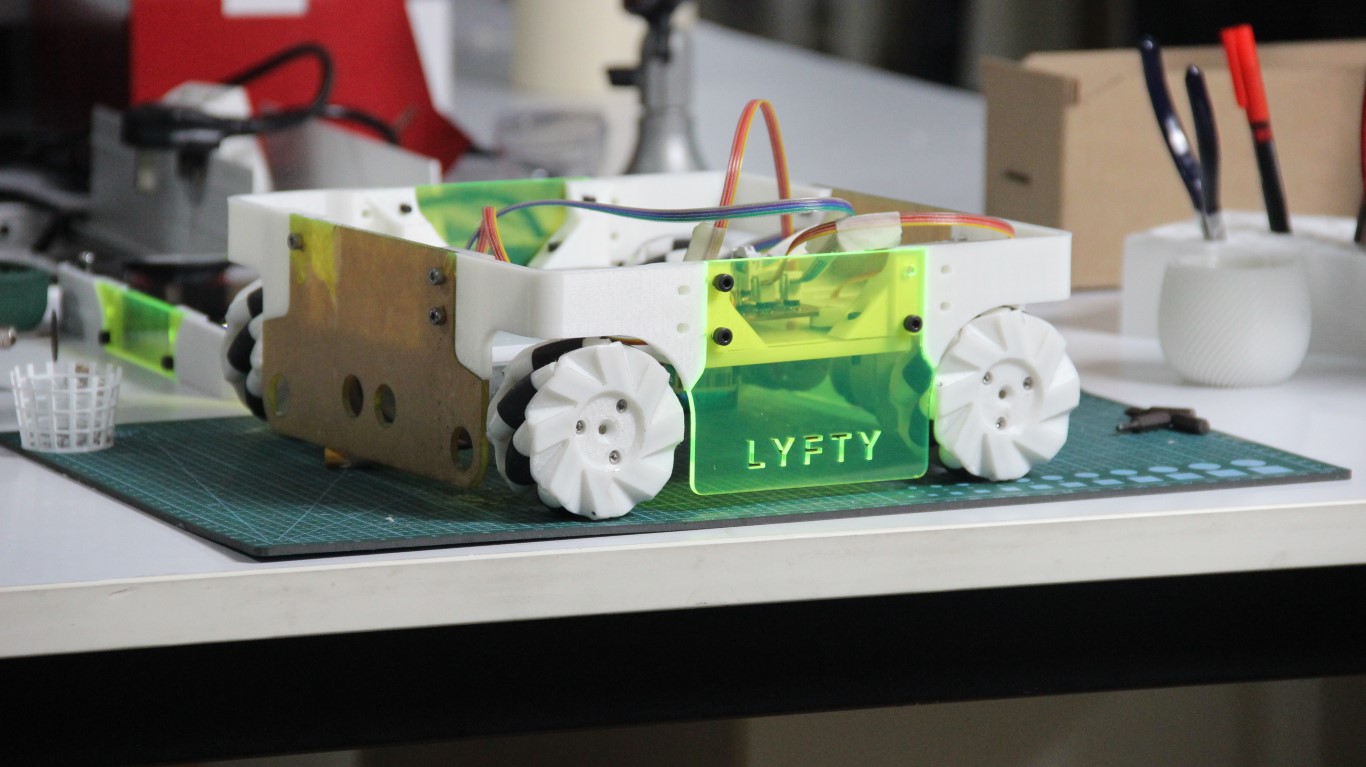
- final testing:
Design files
- Step file of the CAD design:
- Files for laser cutting in acrylic sheet:
- Filer for 3D printing, ( mecanum wheel )
- Filer for 3D printing, ( frame )
- PCB and schematic:
- Arduino codes: