Final Project
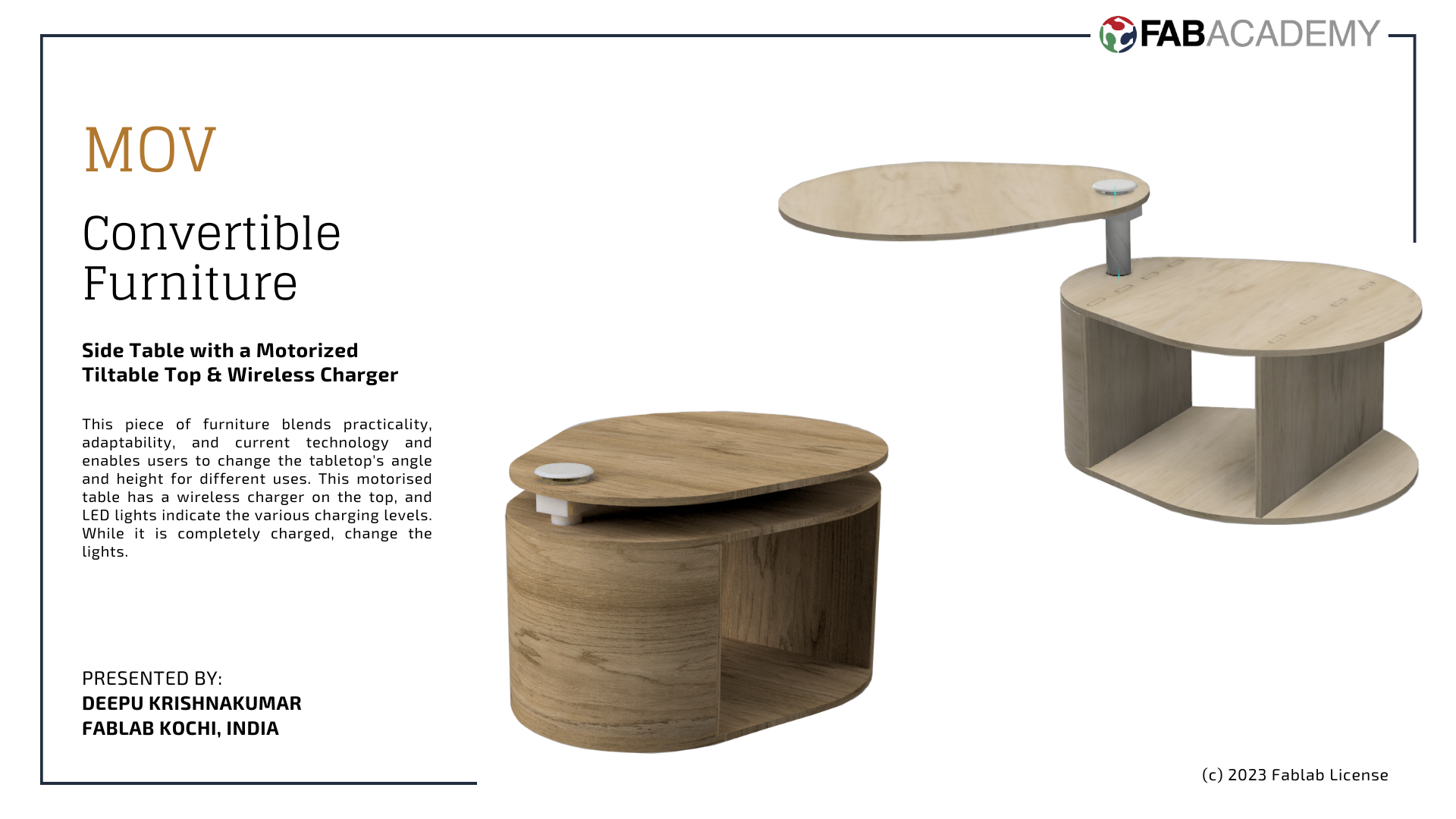
MOV: Revolutionizing Living with Smart Convertible Furniture
I’d like to begin by expressing my gratitude to everyone who has given me the chance to present my final project for the Fab Academy course and has worked with me hand in hand.
In today’s fast-paced world, where space is at a premium and functionality is essential, the demand for innovative solutions that maximise living areas has never been greater. Imagine a world where furniture smoothly transforms from one shape to another, adapting to our ever-changing needs and improving our living spaces. Introducing “MOV”, a ground-breaking collection of smart convertible furniture created to transform how we work, live and interact with our living environments.
In this age of rising urbanisation and shrinking living spaces, I offer you with MOV, my smart and convertible furniture. This cute minimalist piece of furniture has a tiltable table top that can rise and rotate simultaneously to adjust to the level at which we can keep a laptop and work from the comfort of your couch or bed. A wireless charger is also included, allowing you to charge your phone just by leaving it on the table. Furthermore includes an LED that changes colour after a full charge.
Project Management
1. Prototype Design

2. Production

3. Electronics

4. Assembly
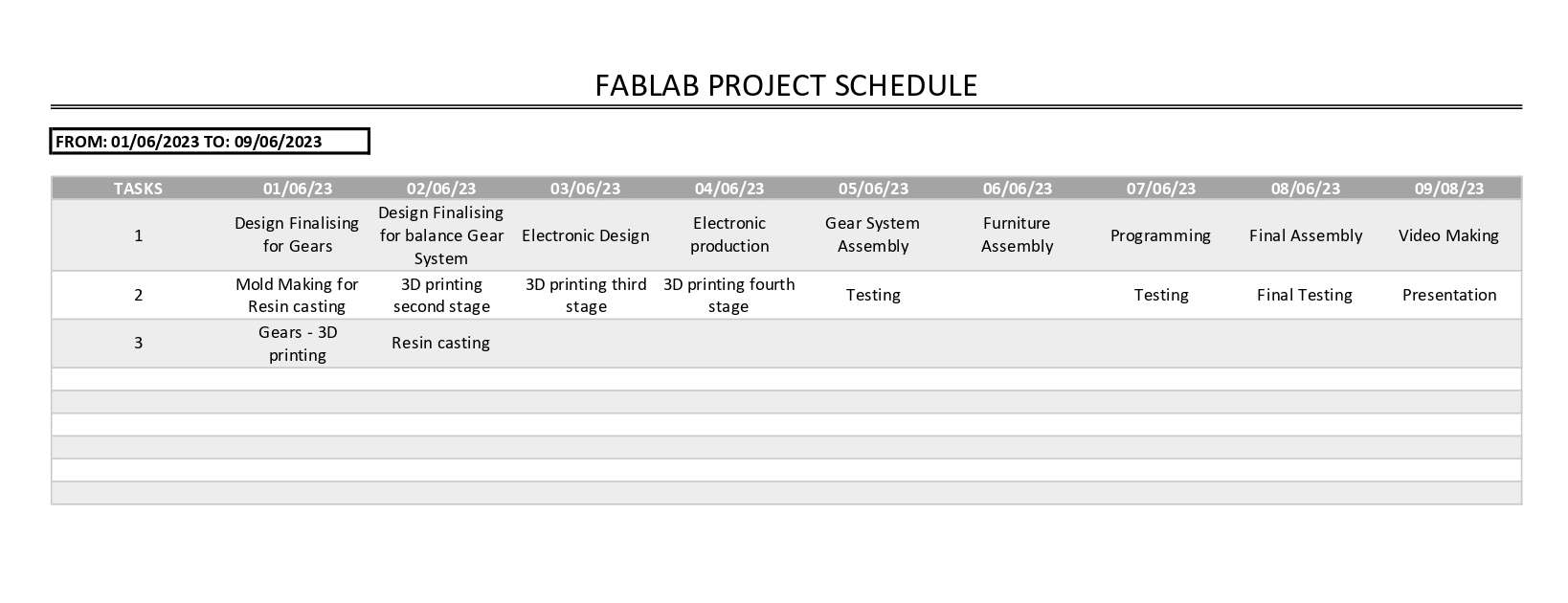
As this is a prototype, I understand that we may not be able to follow a chart. Eventhough I made a plan for the entire process, because a project without a plan is like a never-ending maze, where you wander aimlessly without a direction. So Idecided to split the enitire projects into different parts and decided to design each part and make it ready, test it and then move to other section. So in this way I can work parallel to each stages.
Process Used
Process I used for this project are:
-
Wood CNC milling
-
3D printing
-
Molding & casting
-
Circuit Designing
-
PCB Milling
-
Soldering & Assembling
-
Embedded Programming
Design
After a lot of brainstorming and discussions, I made a basic sketch for an overview.
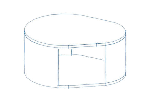
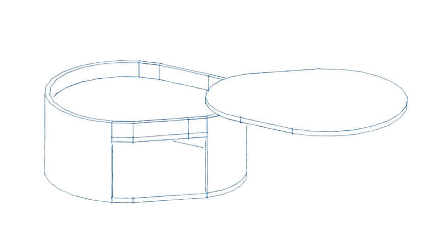
While I was designing, I understood that the true learning sessions had yet to begin. Find out; I’ve still got a lot to learn.
Wireless charger
I started exploring the wireless charger. A wireless charger is a device that allows you to charge compatible electronic devices without the need for a physical connection. It uses electromagnetic fields to transfer power from the charger to the device being charged. One of the most widely adopted wireless charging standards is the Qi (pronounced “chee”) standard.
The Qi standard was developed by the Wireless Power Consortium (WPC), which is an industry group consisting of numerous technology companies. It provides a universal standard for wireless charging, ensuring compatibility between devices from different manufacturers.
Devices that support the Qi standard have built-in coils that can receive power wirelessly when placed on a Qi-enabled charger. The charger itself contains a corresponding coil that generates the electromagnetic field to transfer power to the device. When the coils are aligned, power is transferred efficiently, allowing for convenient and hassle-free charging.
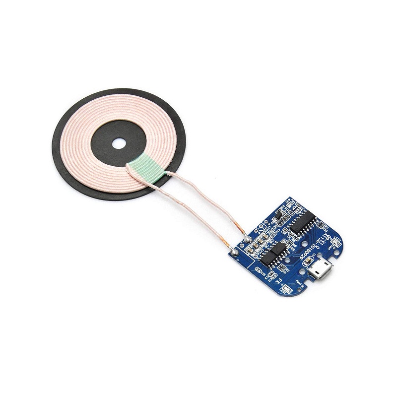
After going through several readily available wireless chargers in market, I decided to purchase one from Robu.in, which is a DC 5V Qi Standard Micro USB Input PCBA Circuit Board With Coil for Wireless Phone Charging.
I purchased this one because I can create my own case that will be compactable to my design.
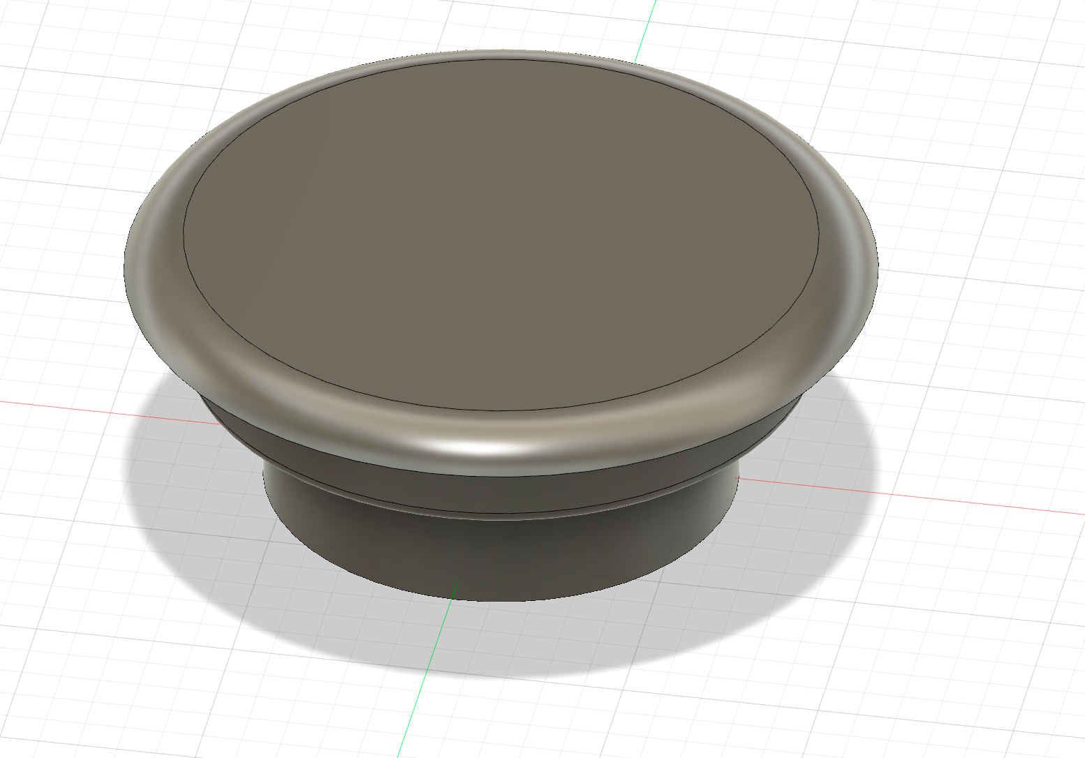
So after finalising this, immediately I ordered the piece online and while it was on transit, I designed a casing for the coil in Fusion 360.
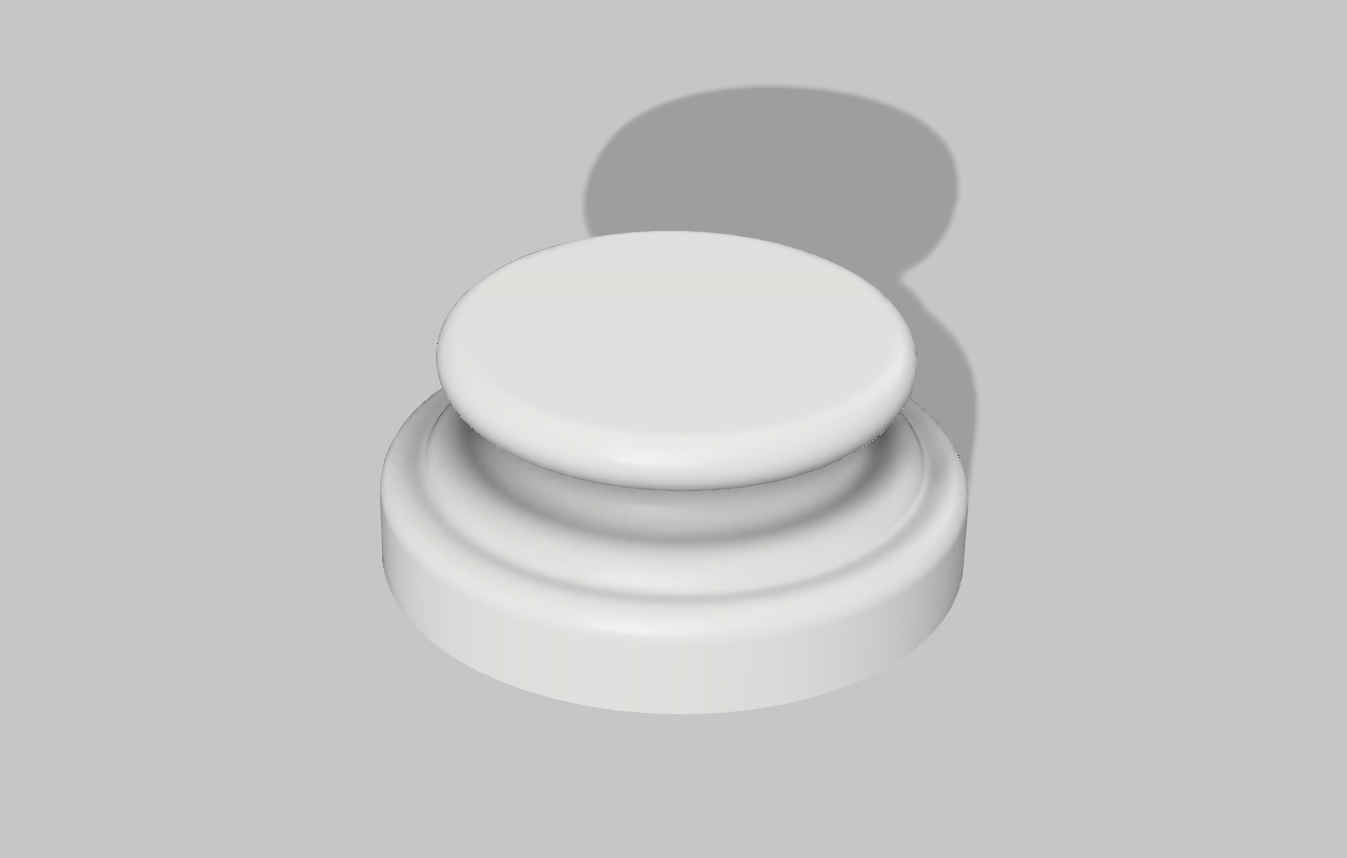
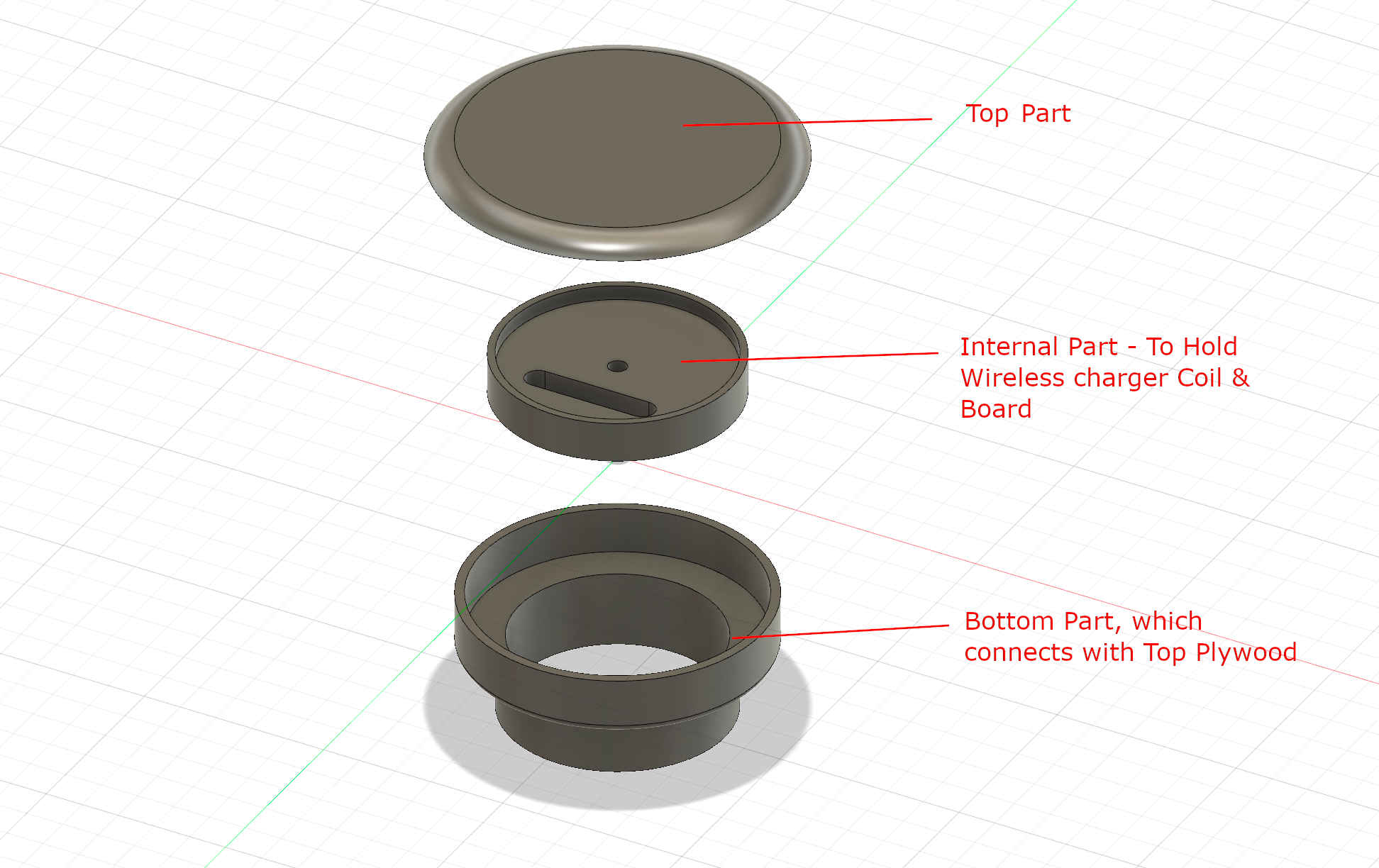
This design was an inspiration from the colonial style wooden handrails. But when I showed this to my tutors, they recommend not to print the same. Since the design has lot of curves and cantilevers which will eventually fail while printing. So I decided to make amendments in design. The revised design comes with 3 parts. 1. Top part which is visble on top of our Table and where the phone can be kept for charging. 2. Internal part which holds the coil and board which is then screwed to top part. 3. Bottom Part, which will go inside the plywood, a 60mm diameter hole is needed on top panel.
I then immediatley take it to 3D printing. We used both Prusa and Sindoh machine for our whole project.
3D printing using the Prusa method is explained in detail in Week 5.

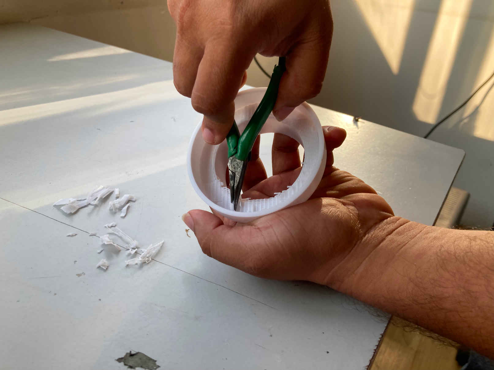
I then cleaned the supports.
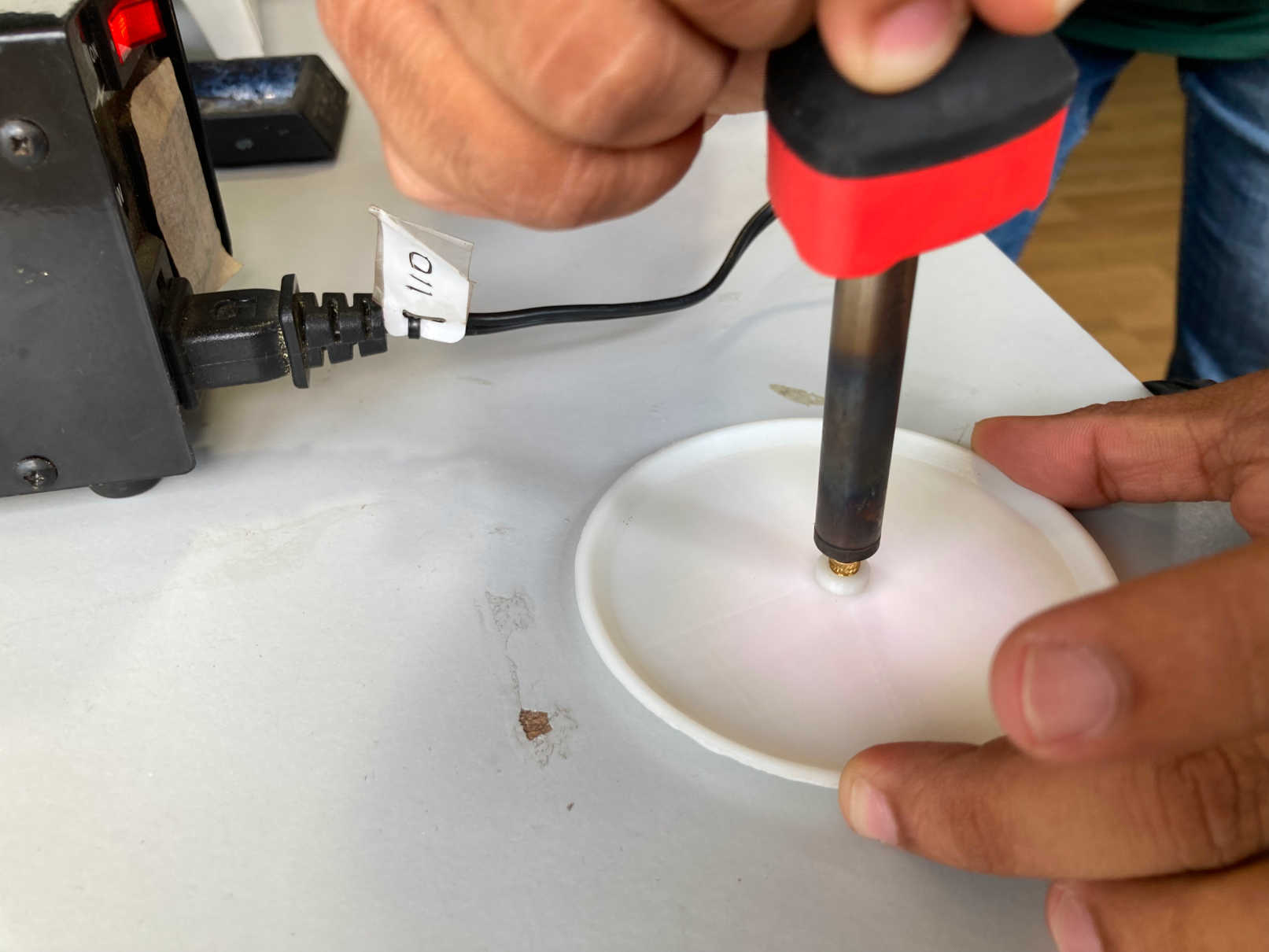
For the top cover I used an M3 insert so that I can use M3 screw to connect both the part.

I assembled everything along with Wireless charger and it worked well.
I then noticed that the LED light wont be much visible since we used PLA for 3d printng. So I decided to make a mold out this 3D printed part and cast the same design in Resin which can create a translucent effect and the light passage will be much better and nice.
So I decided to mold and cast the same parallely while I design the balance.
Molding & Casting
As mentioned earlier I decide to make mold and cast the bottom portion in clear resin. So for that I used the 3D printed part for making a silicon Mold first and then cast the same using clear resin, which we laready used in Molding & Casting Week. One other student Mr.Praveen also wanted to make a mold, so we decided to do this together.
Linear Actuator
The main part of this idea is the lifting and rotating mechanism. For that I have searched lot of mechanism and finally I found this linear actuator which operates on a motor and with the gear system we can make the moving up and down mechanism. But still it lags with the rotation. Everyone suggests me with another motor attached on to the bottom of the top panel. But this loses the minimalism in my design. So I brainstormed again and find our a solution by adding a cylinder on the linear rod with bearings and with helical groves in the cylinder, and the groves passes through a set of bearing attached on the furniture top part, which eventually give the cylinder a rotating action. And with that grove we can control the rotation angle as well.
I immediately went to design the same. Designing gear is a very vast topic and I found some very informative tutorials and with the help of Fusion plugin for spur gear, I made this herringbone gear system.
The gear mechsanism is like this:
3D Printing
As this is a prototype, we will make parts by 3D printing. Like gears, gear box etc.
After all 3D prints are ready I assembled everything.
Electronics
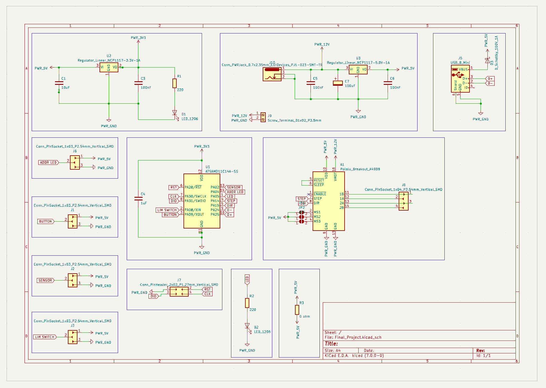
After all the discussions I had with my instructor, I decided to go with SAMD11c microchip, which I already used in my Output devices week. Here in my project I need pins for Current Sensor, Addressable LED, Stepper Motor, Button & for programming. I also adde 1 pin for LEd & another for a limit switch(if in case).
Electronic Design
The schematic I made is shown below:
Now is time to design he PCB. This time I make use of auto routing.
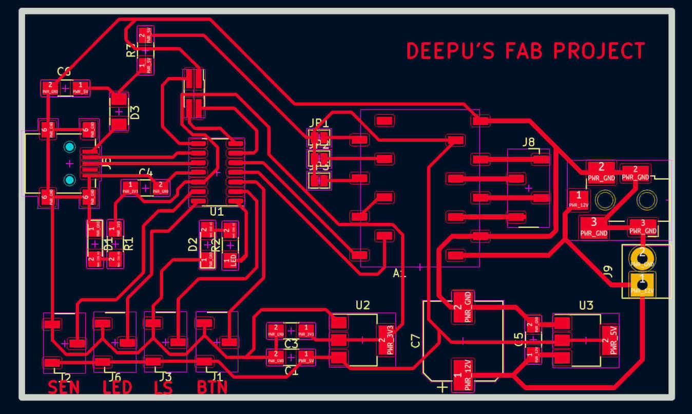
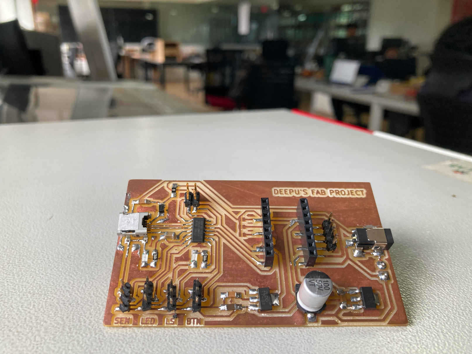
Electronic Production
This time production of PCB seems to be much easier than any other time. No errors occured. The milling and soldering went well. I was so glad that I made this possible, because this was one of biggest fear in this project. Thanks to my tutors as well.
Finally I made the biggest PCB ever in my life.
Furniture
The major part of this project is the furniture itself. Which I made with my Computer controlled Machining Week
My Design
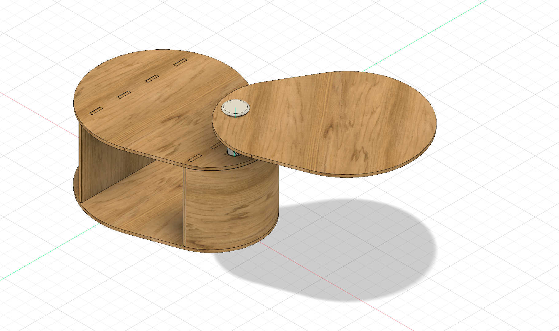
Wood CNC Milling
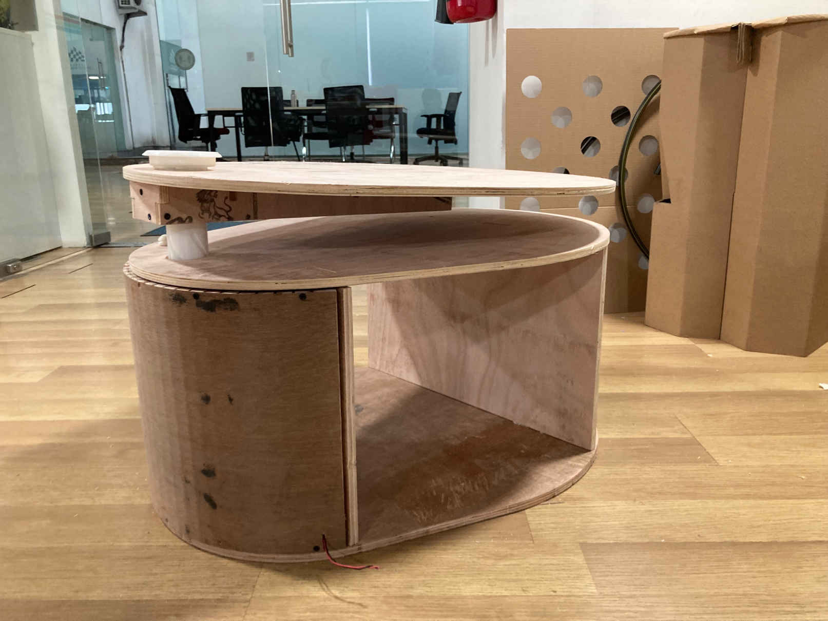
Finished Product
Programming
Programming - the core of this project. I want to program for the stepper motor considering the rotation. Calculate the steps and make prigram accordingly. Then comes the wireless charger. Actually wireless charger doesn’t need any programming, but for the sensor we used for calculating the current needs programming. So that we can control Addressable LED. That needs programming for Addressable LED as well.
So with the help of Jojin I completed the programming.
Bill Of Materials (BOM)
| No | Item/Particulars | Specification/Make | Qty | Unit Rate | Amount | Source |
|---|---|---|---|---|---|---|
| 1 | Plywood | 12mm thick - 8’x4’ size | 1.5 sheet | - | - | Fab Inventory |
| 2 | Stepper motor | Nema 17 | 1 nos | - | - | Fab Inventory |
| 3 | PLA | 1 Roll | - | - | Fab Inventory | |
| 4 | Bearing | - | ||||
| 5 | Smooth Rod | 8mm Dia, 300mm Long | 2 Nos | Amazon | ||
| 6 | Lead Screw with Copper Nut | 350mm Long, Trapezoidal, 4 start, 8mm dia, 2mm pitch | 1 no. | Rs.249 | Rs.249 | Robu.in |
| 7 | Linear Bearing | 2 Nos | Rs.39 | Rs. 78 | Robu.in | |
| 8 | Screws | Fab Inventory | ||||
| 9 | Silicon | Fab Inventory | ||||
| 10 | Resin | Fab Inventory |
Electronics BOM
| No | Item/Particulars | Qty | Source |
|---|---|---|---|
| 1 | Pololu_Breakout_A4988 | 1 | Fab Inventory |
| 2 | Capacitor - 10uF | 1 | Fab Inventory |
| 3 | Capacitor - 100nF | 3 | Fab Inventory |
| 4 | Capacitor - 1uF | 1 | Fab Inventory |
| 5 | Capacitor - 100uF | 1 | Fab Inventory |
| 6 | LED_1206 | 2 | Fab Inventory |
| 7 | D_Schottky_100V_1A | 1 | Fab Inventory |
| 8 | Conn_PinSocket_1x03_P2.54mm_Vertical_SMD | 4 | Fab Inventory |
| 9 | USB_B_Mini | 1 | Fab Inventory |
| 10 | Conn_PinHeader_2x02_P1.27mm_Vertical_SMD | 1 | Fab Inventory |
| 11 | Conn_PinSocket_1x04_P2.54mm_Vertical_SMD | 1 | Fab Inventory |
| 12 | Screw_Terminal_01x02_P3.5mm | 1 | Fab Inventory |
| 13 | Conn_PWRJack_0.7x2.35mm_CUIDevices_PJ1-023-SMT-TR | 1 | Fab Inventory |
| 14 | SolderJumper_2_Open | 3 | Fab Inventory |
| 15 | Resistor - 220 ohm | 2 | Fab Inventory |
| 16 | Resistor - 0 ohm | 1 | Fab Inventory |
| 17 | ATSAMD11C14A-SS | 1 | Fab Inventory |
| 18 | Regulator_Linear_NCP1117-3.3V-1A | 1 | Fab Inventory |
| 19 | Regulator_Linear_NCP1117-5.0V-1A | 1 | Fab Inventory |
| 20 | PCB | ||
| 21 | Addressable LED | 15 cm | |
| 22 | 5V Qi Wireless Charger | 1 No. |
License
This project is licensed with Fab License. (c) 2023 Fab License.
Final Presentation
Acknowledgements
Mr. Ajith, Intern Superfablab, Kochi. Ajith worked with everyone in our lab to ensure that our project was completed successfully. He arrived and assisted me at practically every point. Especially while assembling my furniture together.
Mr. Saheen Paliyil, Alumini 2022, Fab Academy. During Fab Academy, Saheen served as our mentor. His knowledge from Fab Academy and elsewhere enabled us to solve a number of problems quickly. He specifically assisted me with the electronics production and design for my project.
Mr. Jogin Francis, Instructor, Superfablab, Kochi. He is the reason we completed this course. He was a great help to me during every phase of my project, notably the programming.
Downloads
Download Furniture Design File here
Help Taken & Other References
Chat GPT used for doubt clearing and content helps.
How to make a wireless charger with a sound-sensing sparkle(arduino)
Smart DIY Charging Station with LED Notifications | How to Build
Heavy duty linear servo actuator, 12V
How to model Helical and Herringbone Gears
Gear Parameters and Design Tradeoffs
How to measure current using Arduino and ACS712 current sensor
Power Supply Regulator 12v to 5v/3.3v