WEEK08 - Electronics Production
Following the design of week_06, this time we had to finish the board and get it to work. This week showed a lot of existing mistakes. This was the first week I truly struggled with. I wish I had been prepared for electronics earlier.. or the the theory of electronics design and production had been introduced a little earlier.
This board did work in the end, just in time for the lecture, BUT i still chose to re-do it completely in Week9!!! So please also view that board and documentation in terms of electronics design AND production. WEEK9
WEEK EIGHT ASSIGNMENT
| Assignments | Completed |
|---|---|
| GROUP | |
| - characterize the design rules for your in-house PCB production process extra credit: send a PCB out to a board house | GROUP ASSIGNMENT PAGE here |
| INDIVIDUAL | |
| - make and test the development board that you designed to interact and communicate with an embedded micro controller | - done |
| - extra credit: make it with another process | - in progress |
HERO-SHOTS
This board went through alot. The traces still ended up to thin, in one spot the ripped and I had to recreate and re-enforce the line using solder. It worked. so I win. but still.

I designed the board and programmed it so that the eyes would glow from the beginning, and when you press the button they would turn off. As such the button has a pull down resistor.

GROUP ASSIGNMENT
You can find this here.
For the group assignment, we characterized our local PCB-milling machine. In the case of Fablab Kamakura this was the Roland SRM-20. It gets the job done and is good and realiable, but it's nothing fancy, like ones that I've read about, or have seen at the Sony creative lab in tokyo.
To characterize the machine we used Neil's characterization board. Based on this I decided that the traces should be a min of 0.4mm.
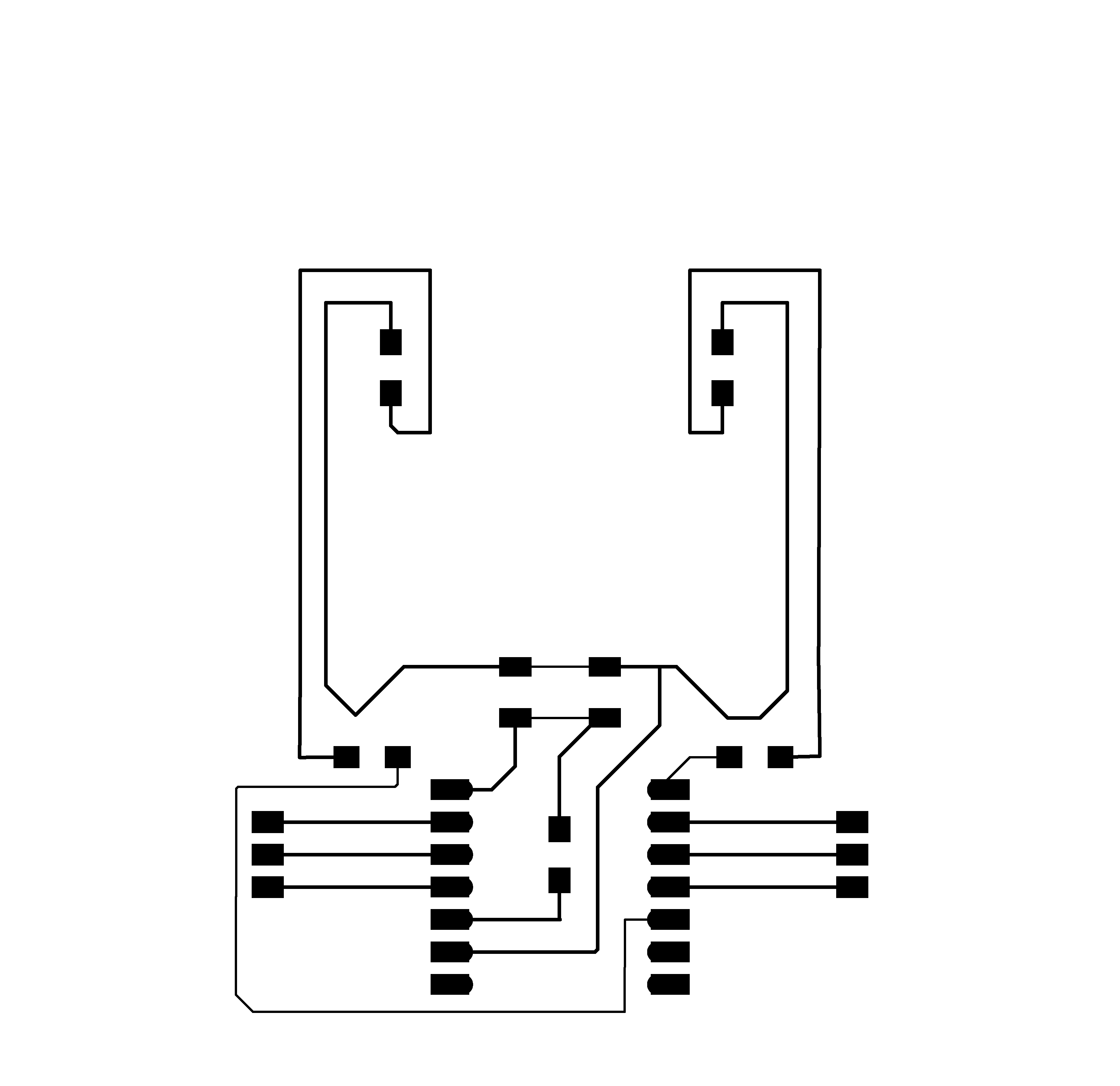
FINISHING DESIGN
I went back this week and defined the design constraints again, now that I had more information following the group assignment.


PREPPING FILES FOR MILLING: MODS
EXPORT AND ILLUSTRATOR
To feed the files to the Roland SRM-20 milling machine, you have to get them through a programm called MODS. but to get the files ready for mods, they first had to go through illustrator and get turned in png's. ( yes MODS also allows for SVG, but this was oddly misbehaving on my computer, also I still had to pull it into illustrator to define the drill holes)
At this step you could also make the board design more funky !
Export SVG.

Load into illustrator: at this step my traces got really thin, but I didn't notice. only next week when I was remaking my board, did I finally realise that this happened because when I imported the board into illusttrator, all the traces-values turned into pt instead of mm but the values stayed the same!
When you do this make sure to keep an eye out for this and apply a conversion.

delete the outside Edge: --> SAVE AS edgecut.png ( just the edge.png)

select all the drill holes and fill them with black: -- > SAVE AS trace.png

then invert the selection ( so that only the traces are selected ) and delete - so that only the drill holes are left:

--> SAVE AS drill holes as drill.png

MODS
This is how you get an .rml file.
Mods is a mysterious beast. I had big issues with it, until I realized it was being caused by my browser. Once I switched to google chrome as my browser, it worked. But it is still not a mac friendly software.
Right click > programs>open server programs>machines>SRM-20>PCB png


Right click near “Roland SEM-20 Milling Machine” > modules>open server module>file>save
Connecting ”save file” inputs file and “Roland SRM-20 Milling Machine” outputs file


Press “select png file” in “read png” and select trace ping. Check the size and dpi.

Change the origin to 0,0,0. Select “mill traces (1/64)” Check the values and press “calculate”. Press “select png file” in “read png” and select interior png. Select “mill traces (1/32)”


PROBLEMA!!!
Suddenly after I tried to invert the colours my MODS was giving me these bizarre artifacts... these turned out to be BROWSER related. I was using BRAVE browser. Once I switched to Google Chrome, the problems disapeared.


USING THIS PROCESS MAKE A TRACE FILE, A DRILL FILE AND AN EDGECUT FILE
MILLING
After I finally had all the rml files I used Vpanel on the Kamakura computer to control the SRM-20
Make sure that the machine is level, and mill a layer of your milling-block if it's the first time it's being used! Also mill a layer off your milling block if you've moved the machine for one table onto another, ( or from one room to another) if you don't the block, or the machine might have the tiniest angle. and then this will happen ;)

The drill bits:


with the 1/64 which is the one you use for traces, please make sure that the tip is intact. it breaks really easily:

set the xy and the z axis


you can run all the pathways one after the other if they require the same drill bit, but I like to load them in one by one just to feel like I'm avoiding errors.... not trusting the machines too much... maybe i don't trust myself to much other ahahah. me and the fab machines should set up a group therapy session. in time for week 10 and 11.


SOLDERING
Later on in the documentation you will realise that I did not solder this part very well. However soldering in the weeks since has become one of my favourite things. I put on a podcast and I really enjoy it. Please view my week 9 documentation here, where I re-designed and remade this whole board one more time, and now after week9 it's actually really cool and amazing!
CODING
I programmed the xiao using Arduino IDE. just to get started I basically combined some led examples with a button example.
// button +led light for fabacademy week8.

// constants won't change. They're used here to set pin numbers:
const int buttonPin = 7;  // the number of the pushbutton pin
const int ledPin1 = 6;    // the number of the LED pin
const int ledPin2 = 2;    // the number of the LED pin


// variables will change:
int buttonState = 1;  // variable for reading the pushbutton status

void setup() {
  // initialize the LED pin as an output:
  pinMode(ledPin1, OUTPUT);
  pinMode(ledPin2, OUTPUT);
  // initialize the pushbutton pin as an input:
  pinMode(buttonPin, INPUT);
}

void loop() {
  // read the state of the pushbutton value:
  buttonState = digitalRead(buttonPin);

  // check if the pushbutton is pressed. If it is, the buttonState is HIGH:
  if (buttonState == HIGH) {
    // turn LED on:
    digitalWrite(ledPin1, HIGH);
    digitalWrite(ledPin2, HIGH);
  } else {
    // turn LED off:
    digitalWrite(ledPin1, LOW);
    digitalWrite(ledPin2, LOW);
  }
}
MENTALHEALTH-BREAK
After nothing working and me being near tears, having soldered, and de-soldered and frankensteined my board I took a mental health break and went to play with Einstein the dog. I hated this week this point. It was making me feel like electronics was never going to work for me.


FIXES
While playing the dog, Rico looked at my board. and concluded that the problem was most likely my soldering. There had been nothing wrong with my button schematic design after-all. Everything was right and correct and all that was needed was more heat... all my tears had been for nothing lol.
FINISHED BOARD
Honestly getting this board to work was a nightmare. I nearly gave up on everything all together. And I still ended up re-doing everything in WEEK9
FILES
RML FILES: meow-rml.zip
ARDUINO CODE: ButtonLED.zip
SVG + PNG files