Week 7: Computer Controlled Machining
Tasks for this week
Group assignment
- Complete your lab's safety training
- Test runout, alignment, fixturing, speeds, feeds, materials and toolpaths for your machine
- Document your work to the group work page and reflect on your individual page what you learned
Individual assignment
- Make (design+mill+assemble) something big
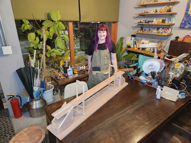
When a rabbit causes an accident on the bridge, who will save the car from plunging to destruction? Along comes our unlikely hero, Turtle, will they be able to save the car? Watch to find out...

Reflection on Group Work
One of the useful methods I learnt this week was first running the job on the CNC mill in the air first. Allowing you to do a check on the job before cutting into your material. This something I will be taking back to implement in my Fab Lab.
Shopbot CNC
The CNC machine that we are using for this week is at MinatoMirai Fablab, which is inside Kanagawa University.
They have a SHOPBOT PRS Standard 96-48
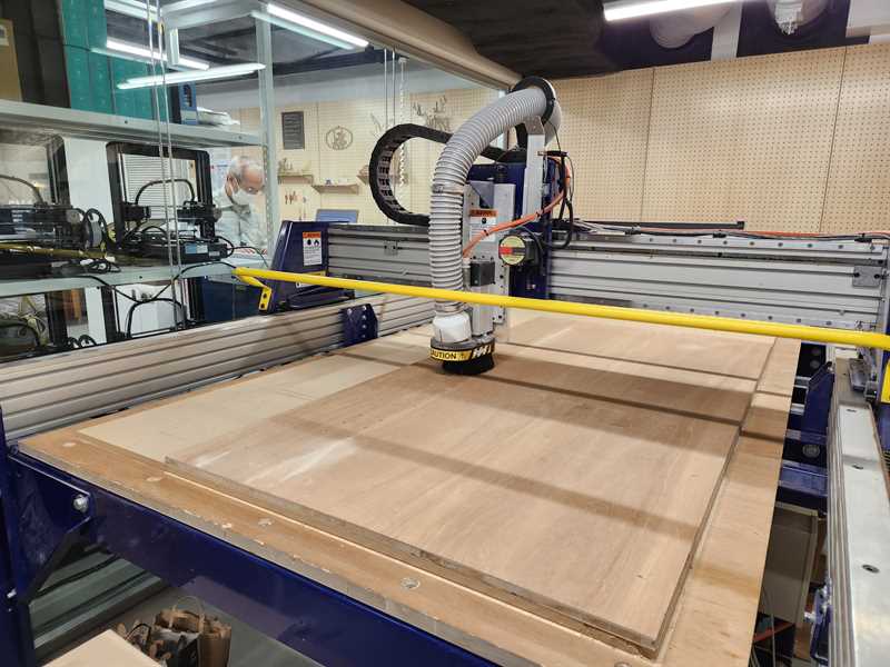
Before using the machine we did a lab safety induction and were given a demonstration by our Fab Academy instructor.
Note: As the CNC was not at Fablab Kamakura and at a University Lab, we were limited in what we could do, as such we did not get to experiment with different tools, speeds and feeds.
Design
I decided to make my design in Fusion 360 (Version 2.0.15050 x86_64).
For the design I was limited in size to a 1820x910x15mm plywood sheet, with a further limit on the CNC mill to 1800x1800 working area.
When thinking about what to make I decided to draw on my engineering background and make a bridge. I first thought of making the Sydney Harbour Bridge
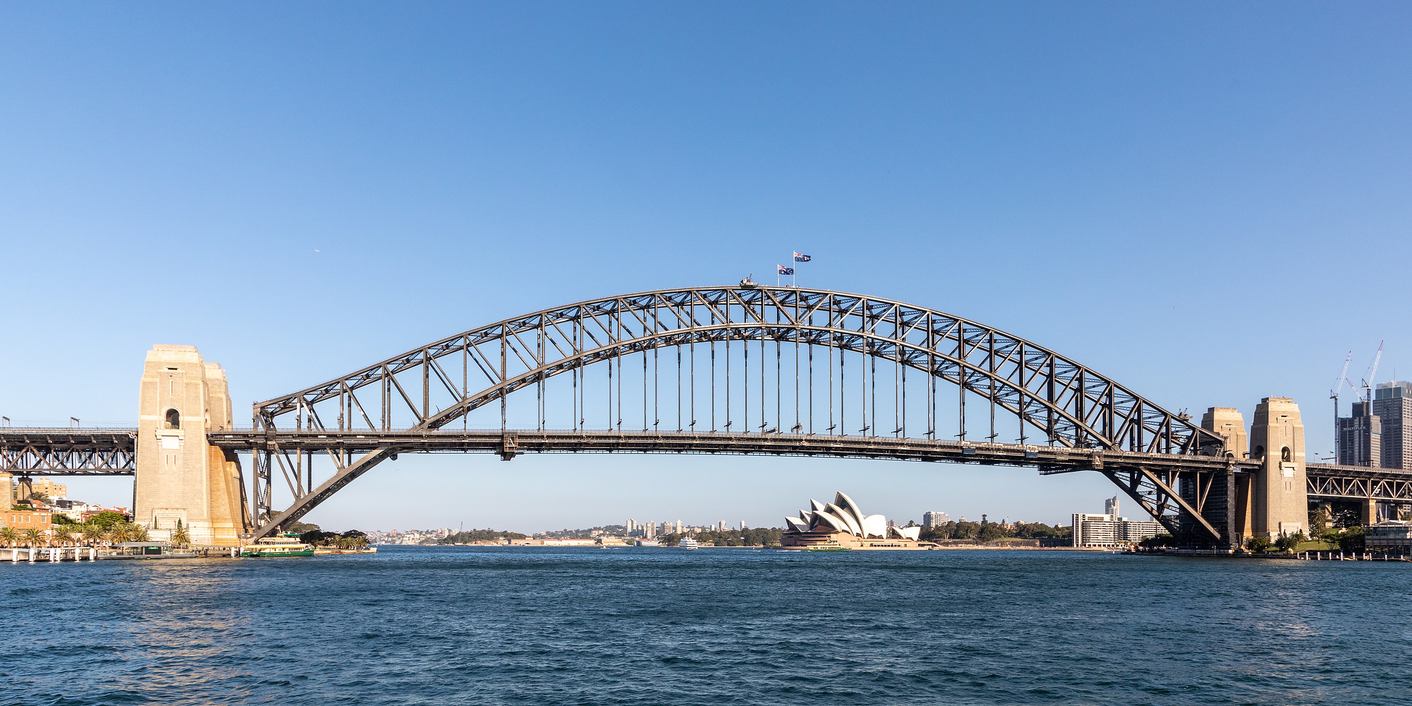
Source: https://en.wikipedia.org/wiki/Sydney_Harbour_Bridge#/media/File:Sydney_(AU),Harbour_Bridge--2019--_2179.jpg
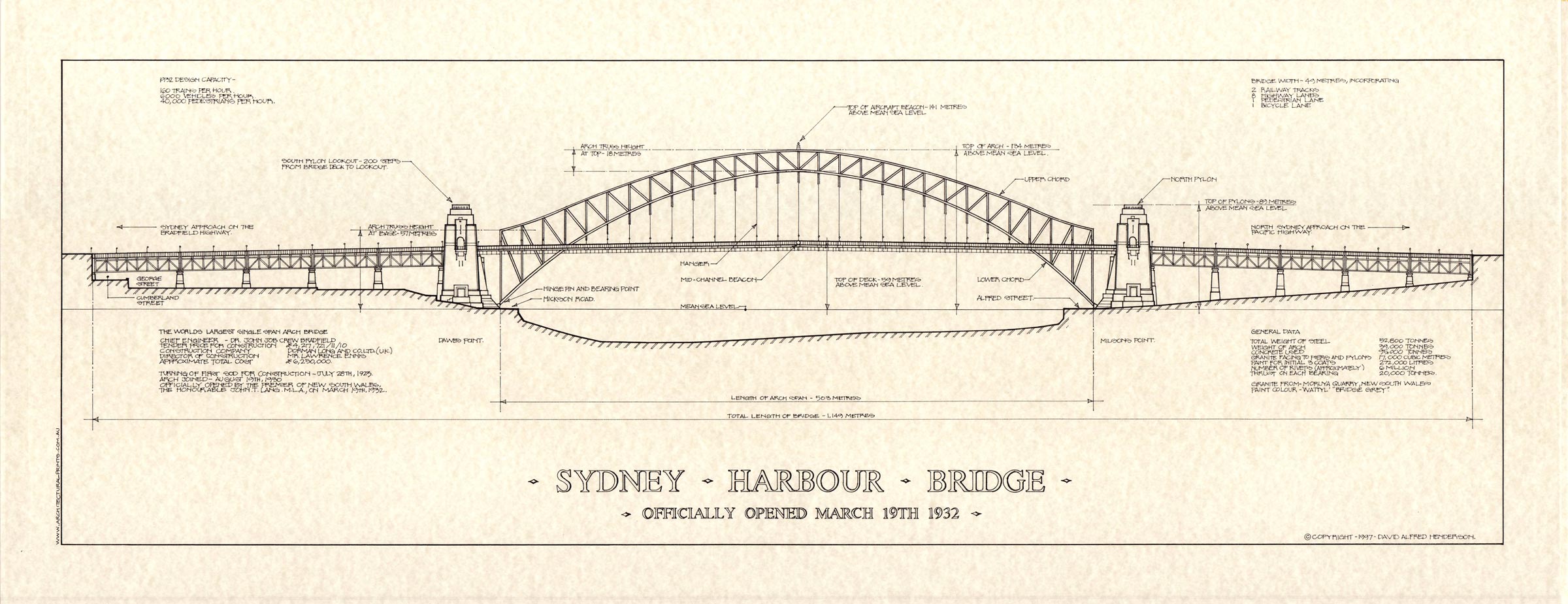
Source: http://architecturalprints.com.au/z49ap/wp-content/uploads/SYDNEY-HARBOUR-BRIDGE-Print-White1.jpg
However this would have required too long to cut, as we had limited time available on the CNC mill.
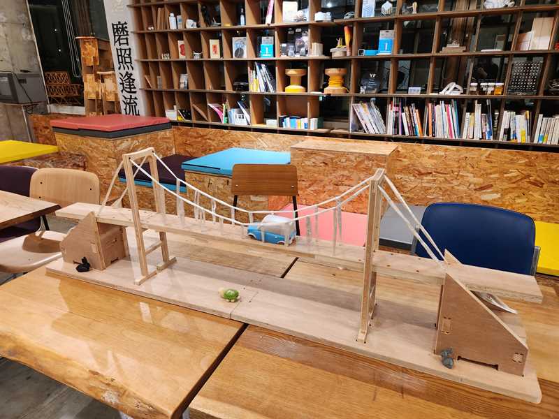
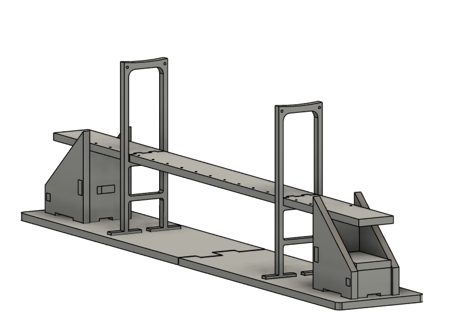
I then decided to go for the Tokyo Rainbow Bridge, a suspension bridge that would require less cutting.

,_Harbour_Bridge_--_2019_--_2179.jpg)
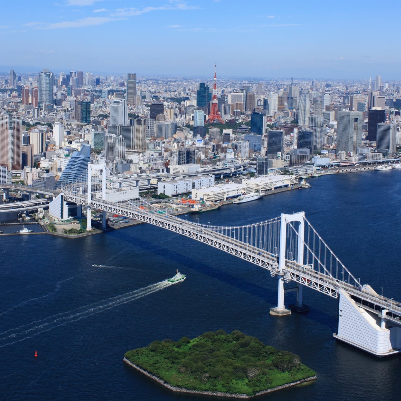
Source: [https://grand-cycle-tokyo.jp/assets/img/top/img_kv_03.jpg] (https://grand-cycle-tokyo.jp/assets/img/top/img_kv_03.jpg)
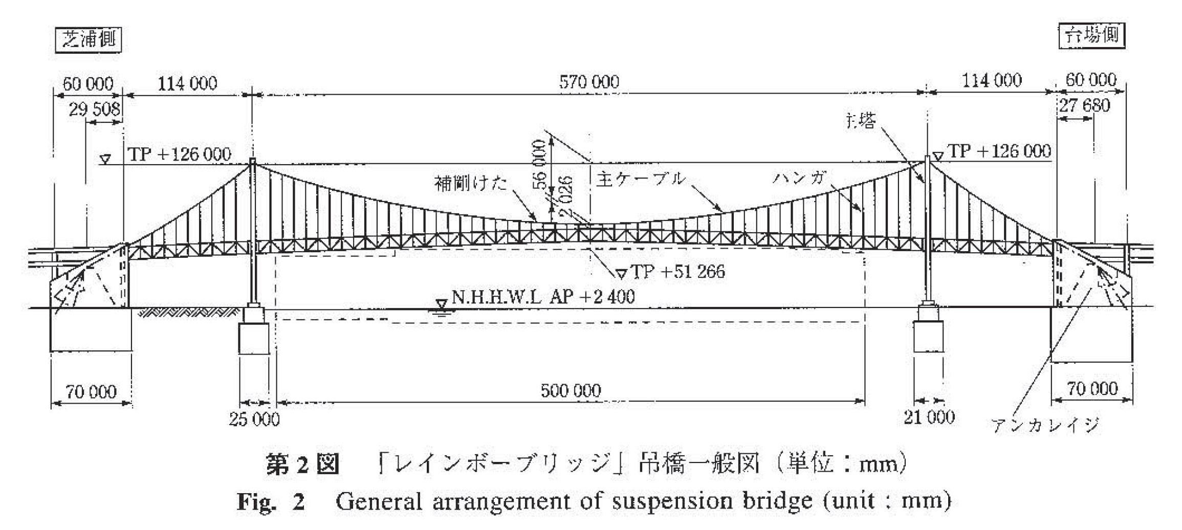
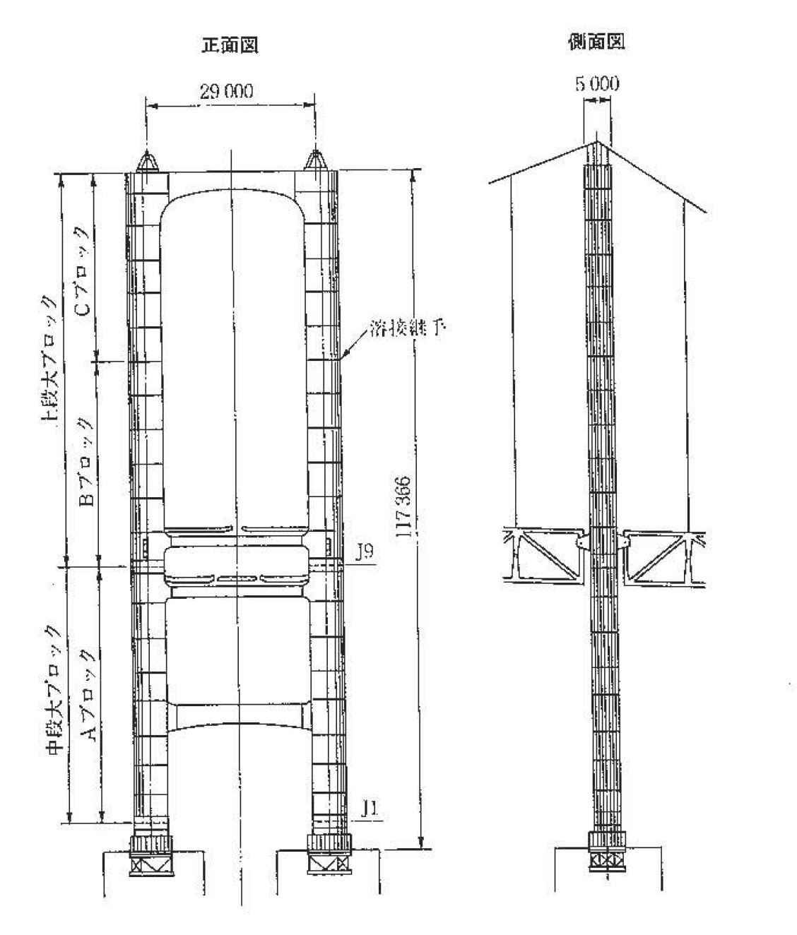
Source: https://www.jasbc.or.jp/gihoudb/1993-1997/ihi/1995-04-21.pdf
I initially tried to make the design exactly to scale, however this would have either resulted in a smaller model that did not lend itself aesthetically to using 15mm thick plywood, or a larger model that was right for the 15mm thickness, but ended up being too large for easy transportation (I am doing this in Japan and need to take back to Australia).
I therefore played with the dimensions to find a balance between scale and aesthetics.
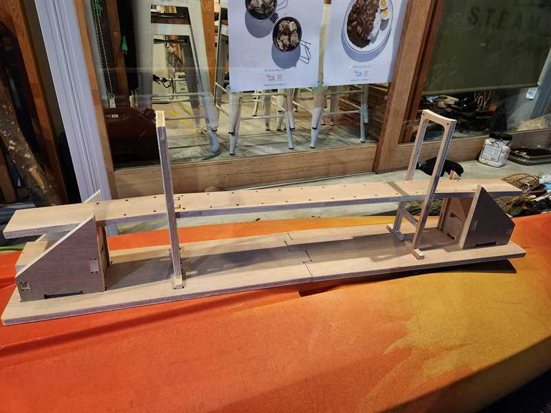
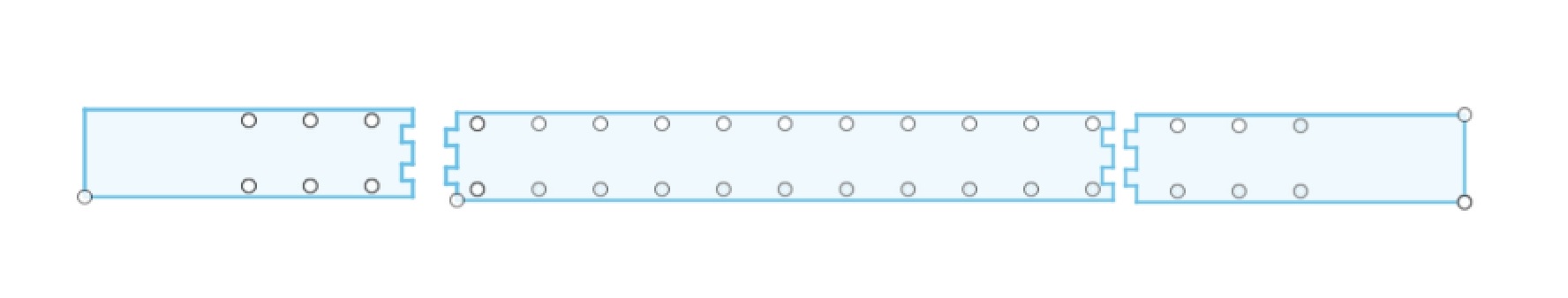
I started by designing the deck of the bridge and the two uprights for the suspension to be attached to. Once I was happy with their scale which I could test by extruding them and moving them to be next to each other, I then designed the end footings.
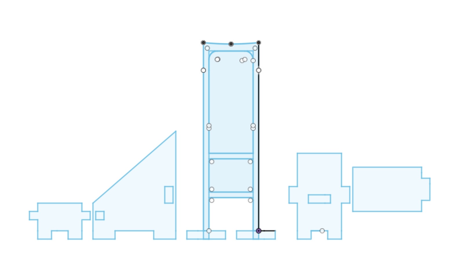
Once I was happy with this and how everything would be spaced out, I designed a base.
I also included breaks in the deck and base to make the model easy to transport.
Note: I had to make an edit to my design, as suggested by my instructors, to separate the deck and base pieces so that they could be cut to be able to best join them back together.
I exported dxf files from Fusion to open in VCarve to create the G-code.
Creating G-code
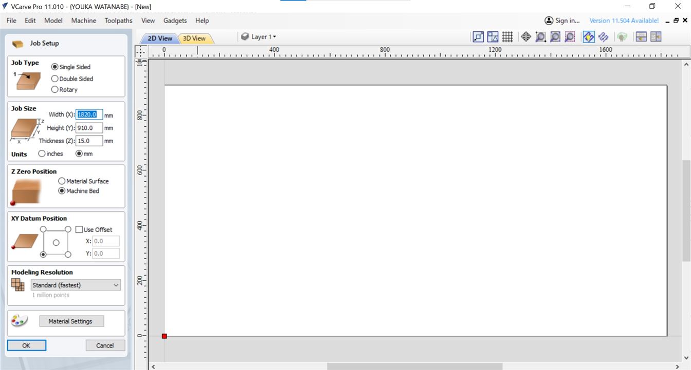
With the design complete I then needed to make the G-code for the CNC. For this I used VCarve Pro 11.
I started by setting up the job size (size of the plywood to be used) which was 1820x910x15mm. I also set the zero point to the machine bed and XY position to the bottom left.
Import dxf file
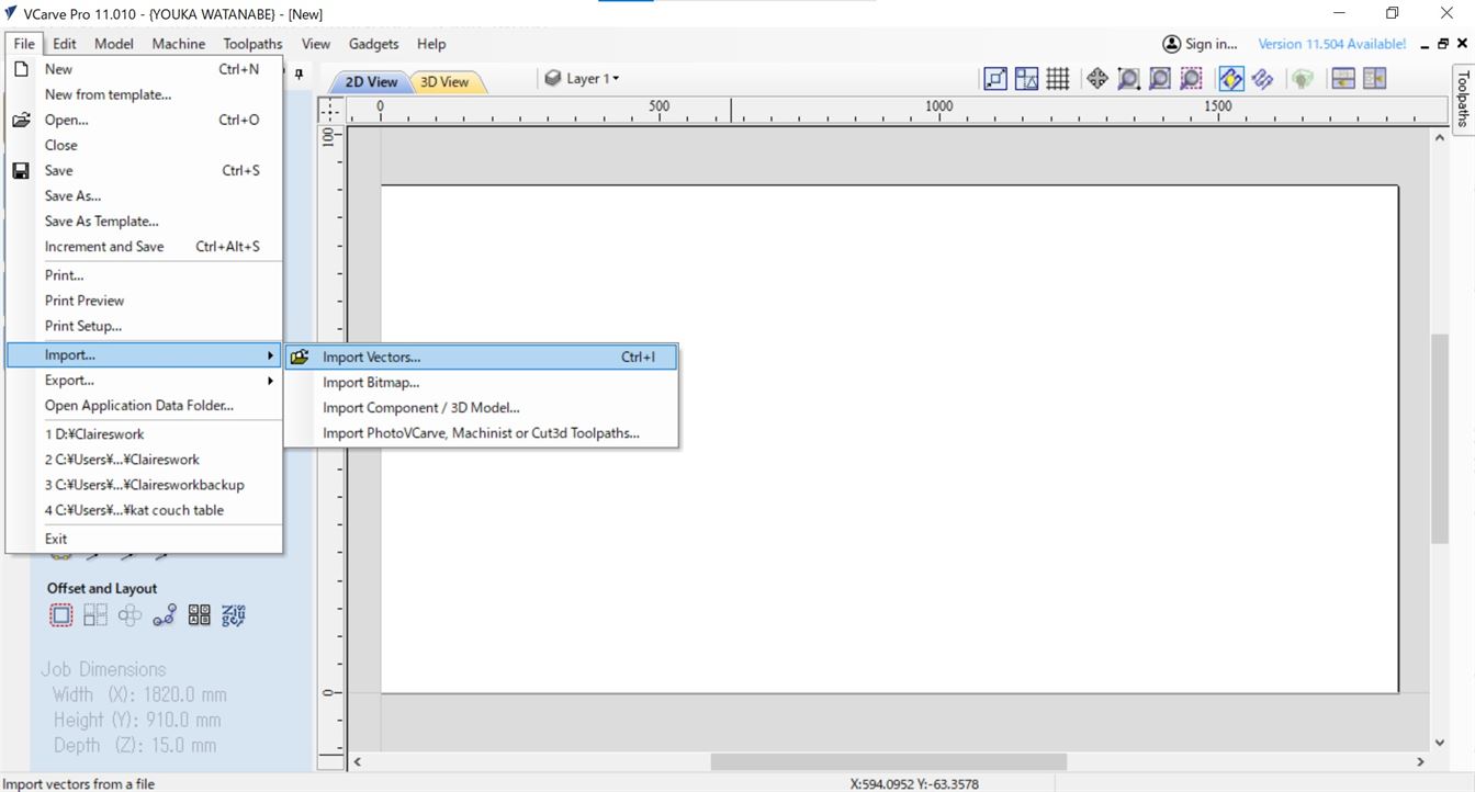
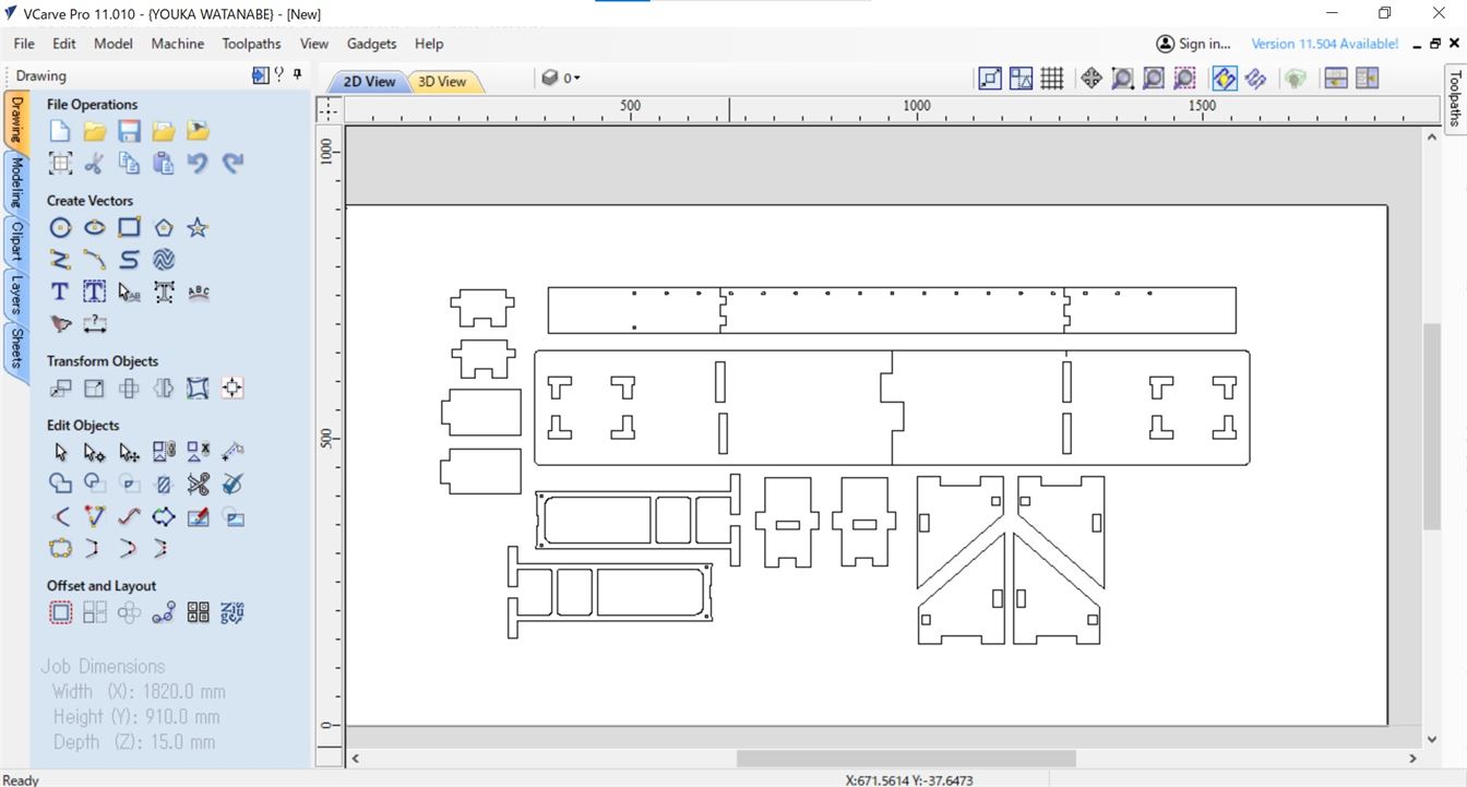
Note: Use the dxf files exported from Fusion, if you load the files into Illustrator and then export them, you end up with a scaling issue in VCarve.
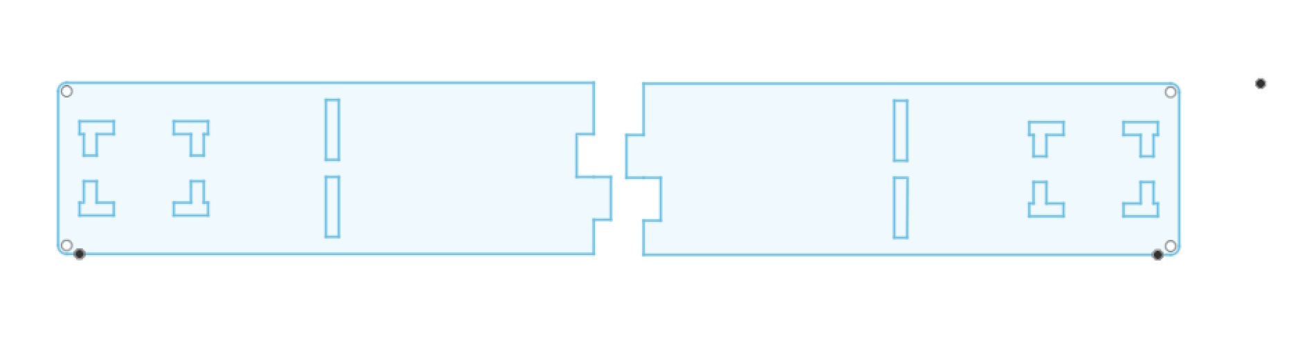
I did run into an issue with not all the cut holes coming through on the dxf export from Fusion. Due to time limitations I was not able to find the cause for this. Note that I used a rectangular array to create the holes. I think the issue may have come from copying the array, rather than making a new array for the second row of holes.
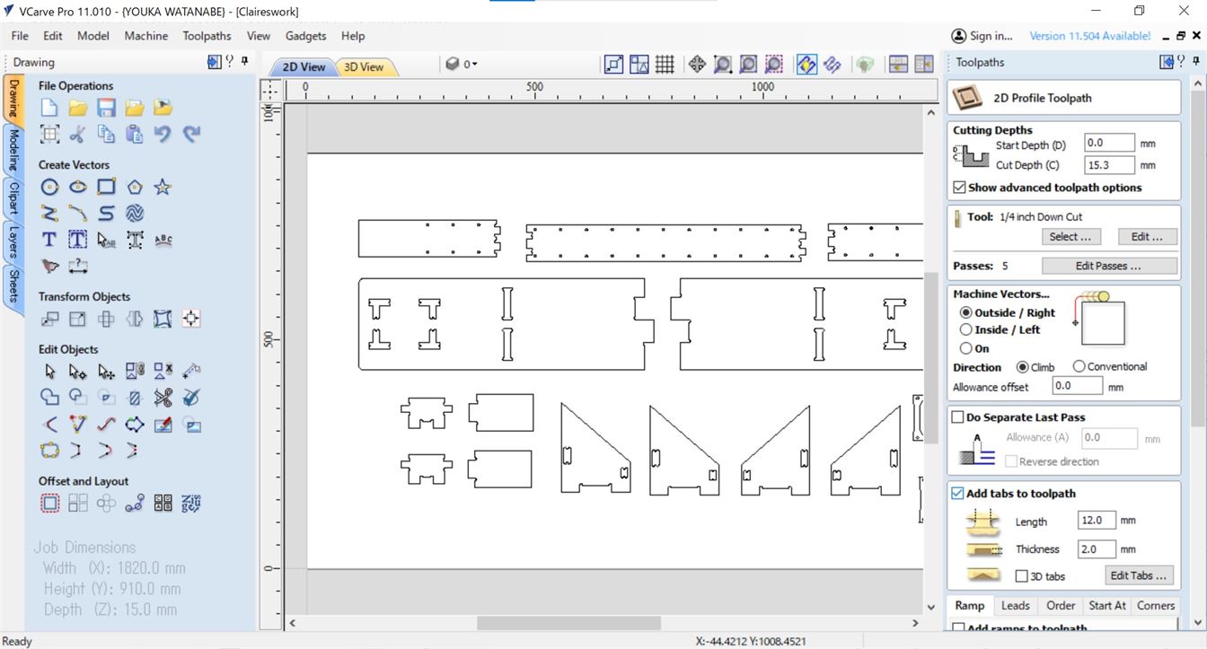
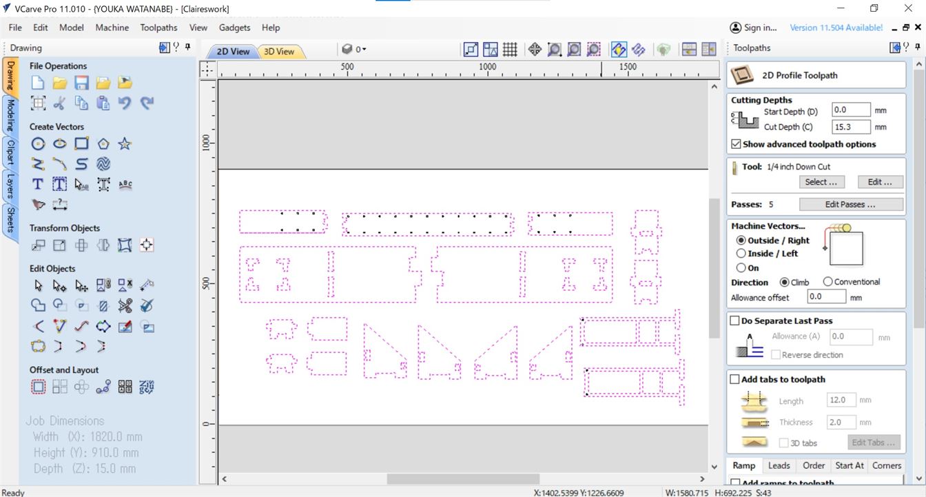
I selected the 2D profile toolpath.
I set start depth as 0mm and for cut depth I used 15.3mm, a bit more than the thickness of the plywood being used.
For tool I selected 1/4 inch Down Cut to match the tool on the Shopbot. Spindle speed was set to 16000rpm, feed rate was set to 2.5 inch/s and number of passes was set to 5 for safe and smooth cutting (as recommended by MintoMirai Fablab staff and Fab Academy instructors).
The machine vectors was set to Outside/Right with direction set to climb and a 0mm offset. Climb milling was selected over conventional as it would deliver a better surface finish.
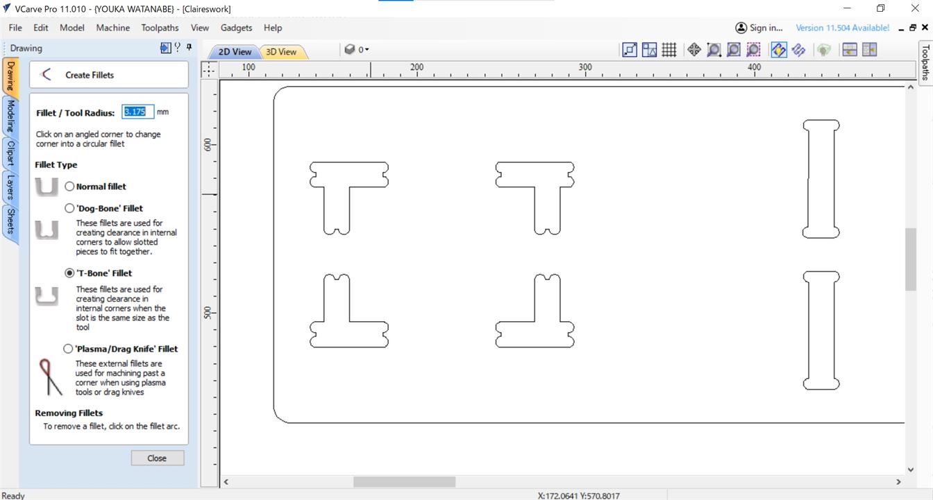
Before generating the G-code I added fillets to the rectangular cutouts/joints in my design to help them fit together better by turning them into 'T-bones'. The fillet size was set to 3.175mm, the radius of the tool (i.e. 0.5*1/4 inch).
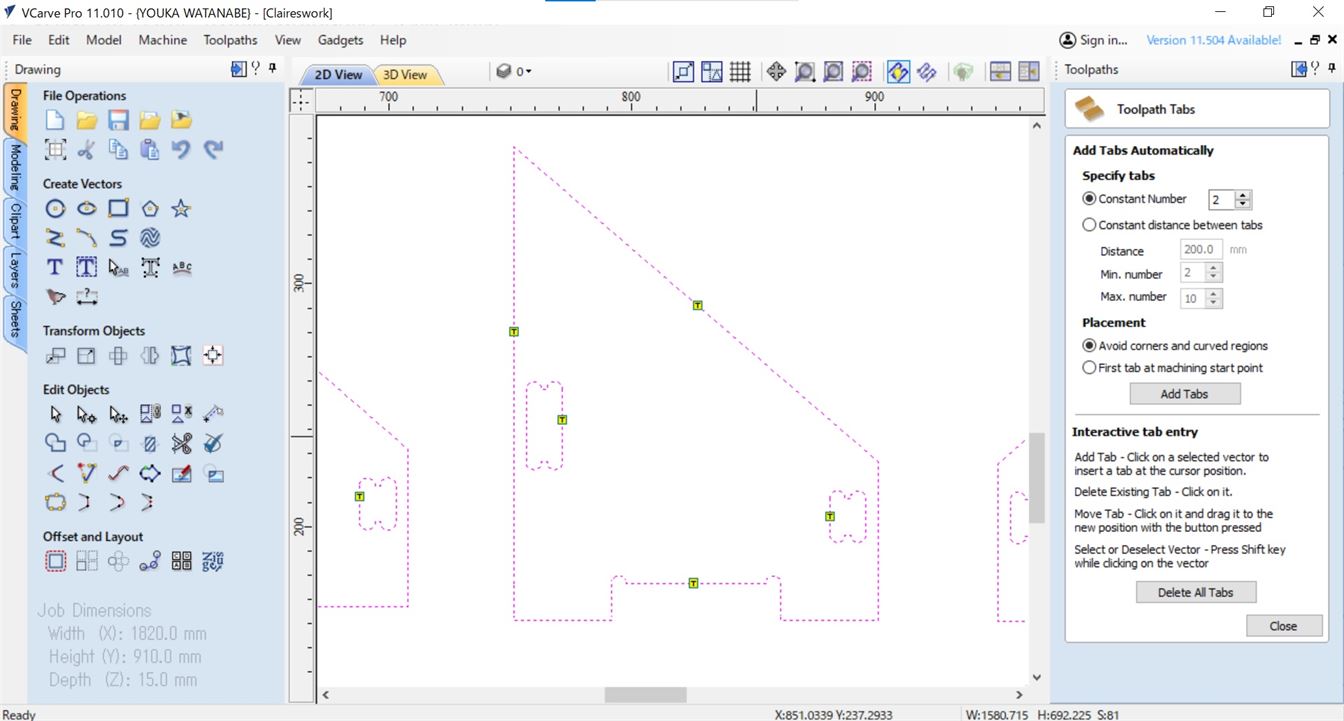
I also added tabs (12mm length, 2mm thickness) to make sure the work did not lift off the sacrificial board and remained connected to the larger plywood sheet.
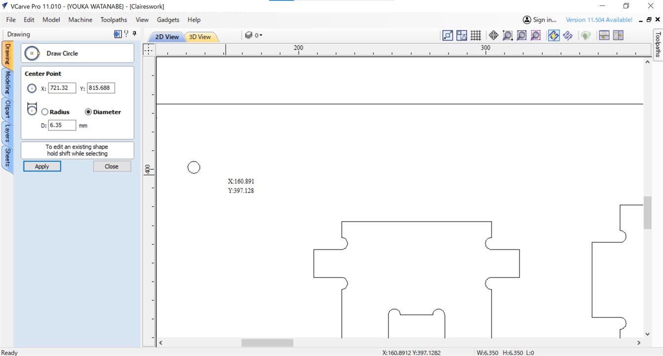
I also added circles where the screws for attaching the plywood to the sacrificial board were going to go, making sure they were spaced both around the outside and between the parts to be cut out so that the plywood would remain securely attached to the sacrificial board while cutting.
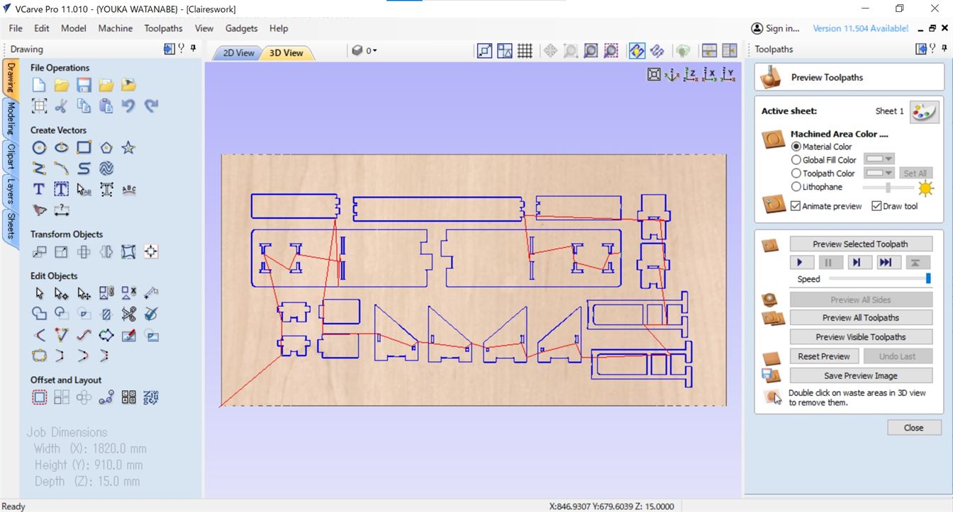
I then used the Toolpath tool to create the G-code.
Separate G-code was created for the screw guide holes, the holes to be cut in the design and the cutting for the design.
For the screw guide holes the toolpath type was set to drilling and the cutting depth was changed to 1mm, as these were to be a guide only on where to drill in the screws to hold the plywood down to the sacrificial board. Tool setting remained the same.
For the holes the toolpath type was set to drilling, but the cut depth remained the same, 15.3mm. Tool settings remained the same.
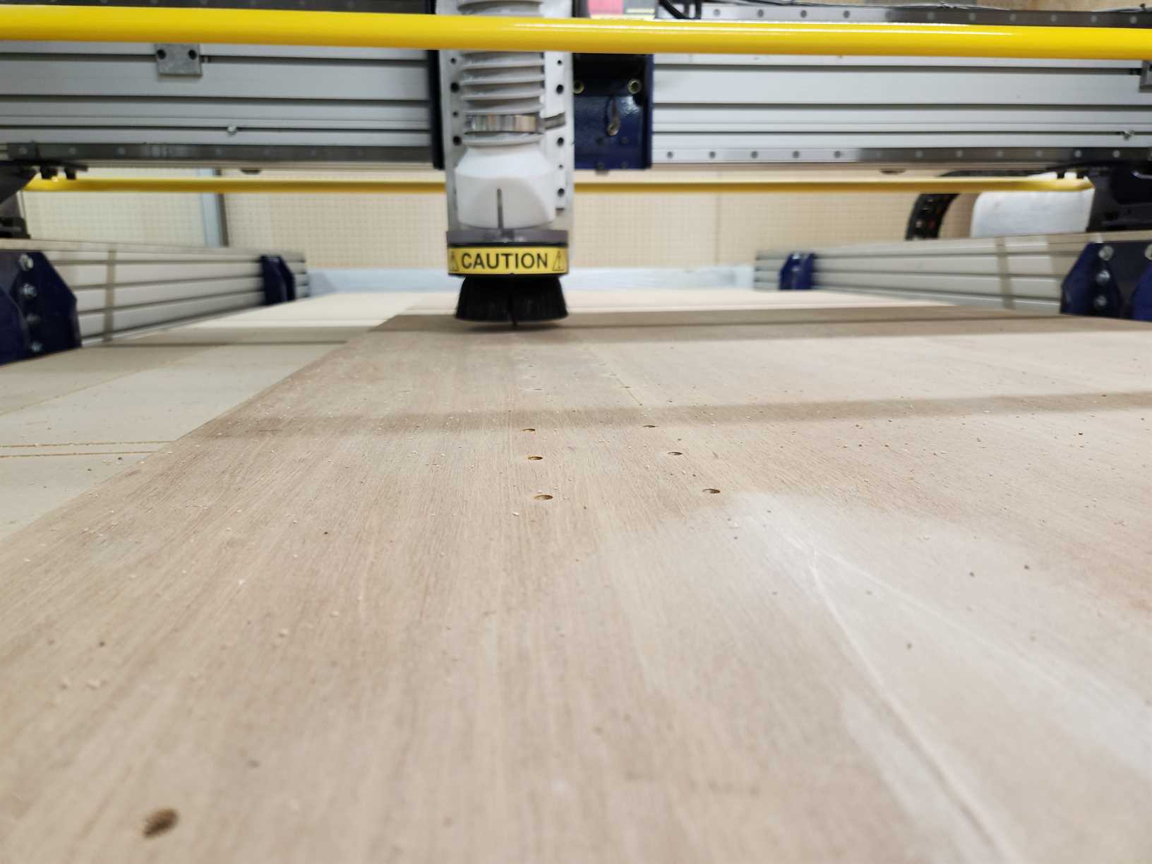
Cutting on the Shopbot
First I cut the guide holes for screwing the plywood sheet to the sacrificial board and then screwed it down using a hand drill and screws.
Second I cut out the holes in my design.
Last I cut out the rest of the design.
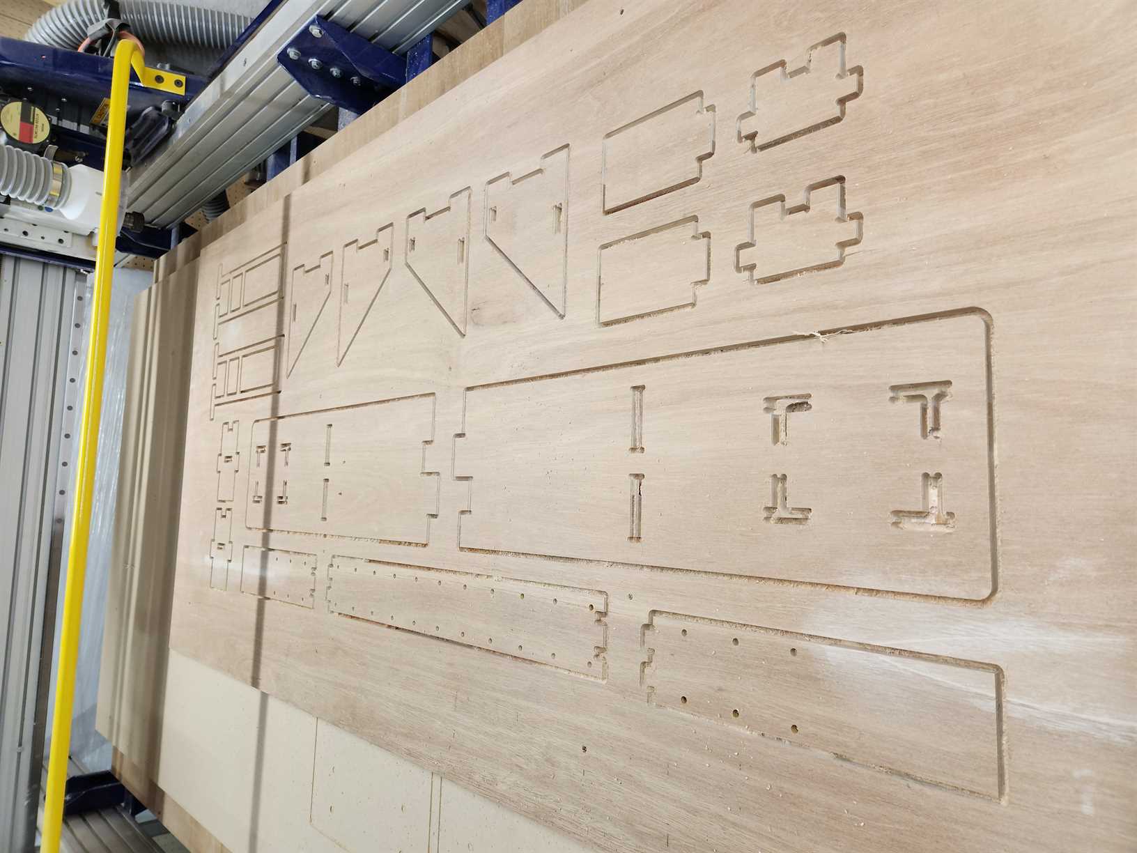
Note: The holes did not cut all the way through the wood (about 1mm short), however as there was not enough time to go back and redo this, I will need to finishing cutting with a drill. This happened even though the depth was set the same as for the rest of the cutting. More experimentation is need on this particular machine to determine solution to this.
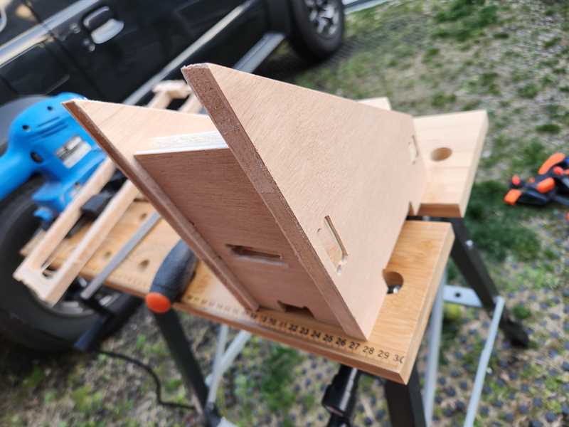
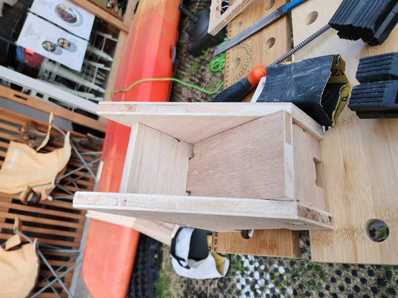
Post Processing
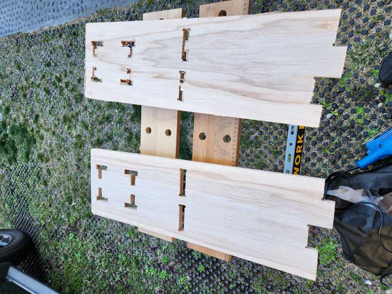
The wood required sanding to get clean edges and also to make the different pieces fit together.
I also needed to drill the holes that did not go all the way through on the CNC.
Sanded vs Unsanded
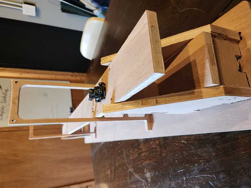
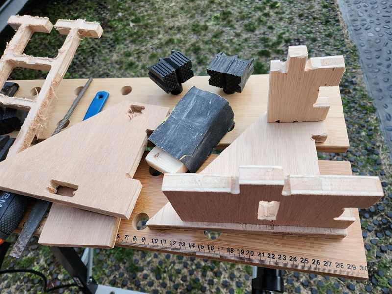
Assembly of end supports
Result
I made a short stop motion film to go with this.
When a rabbit causes an accident on the bridge, who will save the car from plunging to destruction? Along comes our unlikely hero, Turtle, will they be able to save the car? Watch to find out...
Further future enhancements:
- I would like to add lights that make a rainbow pattern to reflect that this is a model of the Rainbow Bridge
- Make a plaque for the model to say what it is
Files
Fusion
dxf base
Vcarve
Gcode Screws
Gcode Holes
Gcode Cutting