04.Embedded programming
In the fourth week I learned, Arduino IDE programming
Assignments of the Week
- Group assignment:
- 1.Compare the performance and development workflows for other architectures.
- 2.Document your work to the group work page and reflect on your individual page what you learned
-
Individual assignments:
- 1.Browse through the datasheet for your microcontroller.
- 2.Program a microcontroller development board to interact and communicate.
Group Assignment:
We tried to use Arduino Uno, Mirco-Bit and Seeed Xiao. Here is the documentation.
Individual assignments:
Browse through the datasheet for your microcontroller:
xiao 2040
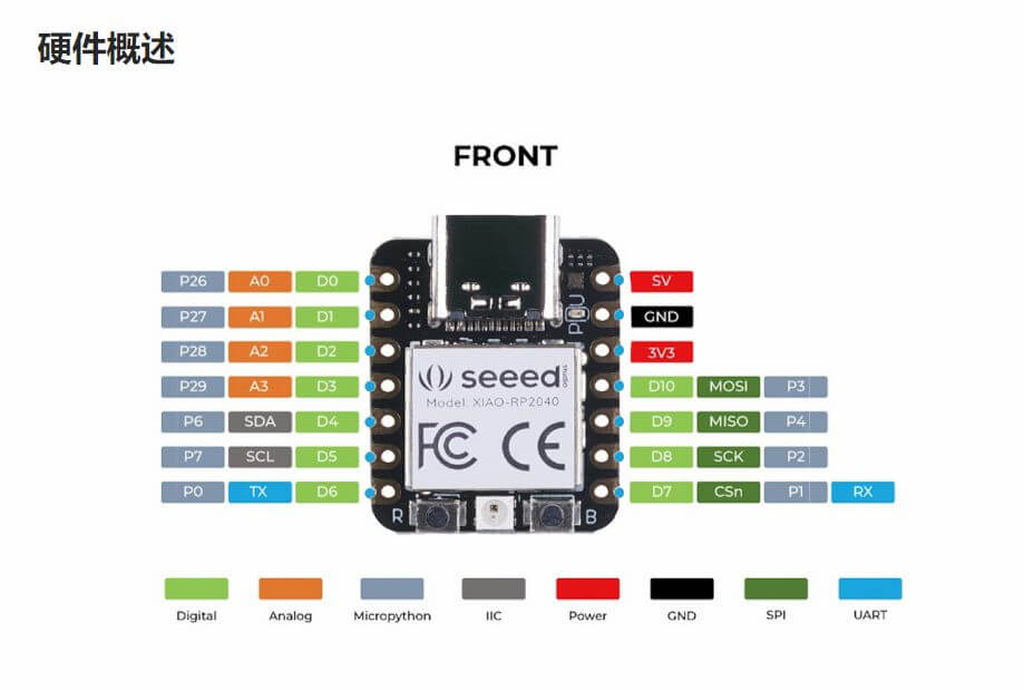
1.Digital = digital pin
2.Analog = analog pin
3.Micropython = Micropython programming
4.IIC\SPI\UART = Protocol
5.Power = positive electrode
6.GND = negative electrode
Program a microcontroller development board to interact and communicate
Arduino UNO projects(Atamega 328)
1.Button to control the fan
2.Vibration Sensor Light
3.Infrared remote control light
4.Potentiometer control a RGB LED
Handpy projects(Esp32)
1.Music box
2.Sound detection alarm
Here's what I learned about programming:
1.int: Integer data type, the range of integers is -32,768 to 32,767 ( -2^15 ~(2^15)-1). Integers use 2's complement to store negative numbers. The highest bit is usually the number bit, indicating the sign of the number. The remaining bits are "unincremented by 1".(Arduino can handle negative calculations. However, when the right shift position operator is used for integer values, unpredictable compilation results may occur)
grammar:int ledPin = 13;
2.Int():converts a value to int
grammar:int(x);
3.Long: A long integer variable is an extended digital storage variable, which can store a variable of 32 bits (4 bytes), Values from -2,147,483,648 to 2,147,483,647.
grammar:long var = val;
4.Long():Converts a value to the long long data type.
grammar:long(x);
5.If: Through the if command, the user can let the Arduino judge whether a certain condition is met, and execute the corresponding program according to the judgment result.
grammar:if(expression) {
            statement block
            }
6.INPUT: When the pin is set to input (INPUT) mode, the pin is in a high impedance state (100 megohms). At this point this pin can be used to read sensor signals or switch signals.
7. INPUT: When the pin is set to input (INPUT) mode, the pin is in a high impedance state (100 megohms). At this point, this pin can be used to read sensor signals or switch signals.
8.pinMode(): Through the pinMode() function, you can configure the Arduino pins to the following three modes:
Output (OUTPUT) mode: When the pin is set to output (OUTPUT) mode, the pin is in a low impedance state. This means that the Arduino can supply current to other circuit components. That is, the Arduino pin is outputting In (OUTPUT) mode, the LED can be lit or the motor can be driven. (If the driven motor needs more than 40mA current, The Arduino will need transistors or other auxiliary components to drive them. )
Input (INPUT) mode: When the pin is set to input (INPUT) mode, the pin is in a high impedance state (100 megohms). At this point, this pin can be used to read sensor signals or switch signals.
Input pull-up (INPUT_PULLUP) mode (only supports Arduino 1.0.1 and later versions): Arduino microcontrollers have their own internal pull-up resistors. If you need to use the internal pull-up resistor, you can set the pin to input pull-up (INPUT_PULLUP) mode through pinMode().
9.digitalWrite(): Write digital pins HIGH (high level) or LOW (low level).
grammar:digitalWrite(pin, value);
10.= : Assignment operator (single equal sign), store the value on the right side of the equal sign into the variable on the left side of the equal sign
grammar:int sensVal;
      senVal = analogRead(0);
11.unsigned char: An unsigned data type occupies 1 byte of memory. Same data type as byte. The unsigned char data type is used to store characters with ASCII codes 0 to 255. For the consistent programming style of Arduino, try to use byte data type instead of unsigned char data type.
grammar:unsigned char myChar = 240;
12.attachInterrupt(): It is used to set up and execute ISR (Interrupt Service Routine) for Arduino development board
ISR (Interrupt Service Routine), as the name implies, interrupts what Arduino is currently processing and gives priority to executing the interrupt service routine. When the interrupt service routine is completed, come back and continue to execute the things just executed. Interrupt service routines are useful for monitoring Arduino inputs.
We can use the attachInterrupt() function to use the Arduino pin to trigger the interrupt routine. The following list describes which pins support interrupts:
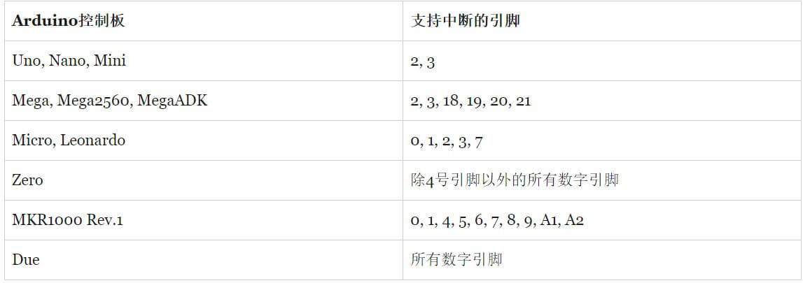
grammar:attachInterrupt(digitalPinToInterrupt(pin), ISR, mode);
13.delay(): The delay() function can be used to suspend program execution. The pause time can be controlled by the parameters of the delay() function, and the unit is milliseconds (1 second = 1000 milliseconds).
grammar:delay(ms);
14.++: equivalent to i = i + 1;
15.#include: Used to include external library files in the program.
16.!: Returns true if operand is false (negates operand if false)
17.Serial.begin(): Set the data transmission rate (number of bytes transmitted per second) when the computer communicates with the Arduino serial port. The following rates are available: 300, 600, 1200, 2400, 4800, 9600, 14400, 19200, 28800, 38400, 57600, or 115200. , you can also set other transmission rates according to the device you are using.
grammar:Serial.begin(speed);
18.(&):The bitwise AND operator is a single ampersand (&). If both bits are 1, the result is 1, otherwise the result is 0.
19.map():map() can be used to proportionally map a value from one interval to a new interval.
grammar:map (x, in_min, in_max, out_min, out_max)
20.println():Send data to the serial port in human-readable ASCII code, similar to the print() command, but with a newline.
grammar:Serial.println(val)
    Serial.println(val, format)
21.delay():The delay() function can be used to suspend program execution. The pause time can be controlled by the parameters of the delay() function, and the unit is milliseconds (1 second = 1000 milliseconds).
grammar:delay(ms);
22.analogWrite:Write an analog value to an Arduino pin. This operation can be used to control the brightness of the LED, or control the speed of the motor. Every time the Arduino executes the analogWrite() command on the pin, it will give the pin a PWM signal with a fixed frequency. The frequency of the PWM signal is about 490Hz.
In the Arduino UNO controller, the PWM frequency of pin 5 and pin 6 is 980Hz. In some ATmega168 and ATmega328 based Arduino controllers, the analogWrite() function supports the following pins: 3, 5, 6, 9, 10, 11.
grammar:delay(ms);
Below is the programming hardware I used in the project
relay
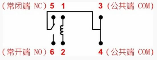
1. We can understand the relay as a "switch", which is a "switch" that uses a relatively small current to control a large current. This is just to let beginners understand the working principle of the relay, so no larger power supply device is used, it is necessary to choose A DC motor that can be driven by 5V.
2.This relay has a total of 6 pins. 1,2 pins are used to connect Arduino digital pins and GND. Drive the relay through a digital pin. The two ends of 1 and 2 are the two ends of the coil. After Arduino gives HIGH, there is current in the coil, and the coil will generate magnetism (like a magnet), Pull the contact in the middle (you can hear a "click"), and the normally open end (NO) will be connected to the common end. Conversely, if Arduino gives LOW, When there is no current in the coil, the normally closed terminal (NC) is connected to the common terminal.
DC
1. Ordinary DC motors are motors that we have more contact with. Generally, there are only two pins, which can be turned on when the power is turned on, and reversed when the positive and negative poles are reversed. As you can see, it is doing a circular motion over and over again, and cannot control the angle, but it can drive the board through the motor, The speed can be controlled, but because the speed of the ordinary motor is too fast, it is generally not directly used in the smart car.
2. The DC geared motor is to add a gear box to the ordinary motor, which reduces the speed and makes the ordinary motor have a wider use space. For example, it can be used in smart cars. The speed can also be adjusted by PWM.
3. A servo is also a type of motor that uses a feedback system to control the position of the motor, which can be used to control the angle. so, Servos are often used to control the rotation of some robot arm joints.
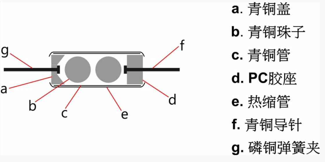
Ball switch
1. Ball switch, also called bead switch, vibration switch and so on. Although the names are different, the principle is the same. It is to control the on-off of the circuit by the principle that the beads roll and contact the guide pin. Look at the structure diagram to understand.
2. There are two balls inside the ball switch, and the circuit is turned on or off by the principle that the balls roll and contact the guide pin. When the sensor is shaken or shaken, the bead touches the guide pin and conducts. It is also important to note that due to the internal construction of the ball switch, Only one end of the ball switch is conducting, the end of the gold guide pin is conducting, and the end of the silver guide pin is not conducting. That's why, The reason why the lamp will light up when it is tilted towards the gold end, but it will not be lit when it is tilted towards the silver end
RGB LED
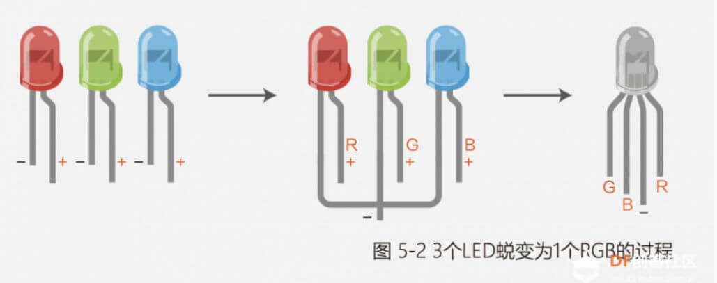
1. The RGB light has 4 pins, the R, G, and B pins are connected to one end of the LED light, and the other pin is the common positive pole (yang) or the common cathode (negative). What we choose here is common cathode RGB. Look at Figure 5-2 below, and you will understand. It shows how three LEDs transform into one RGB gorgeously. R, G, and B are actually the positive poles of the three LEDs, and their negative poles are pulled to a common pin. Their common pin is the negative pole, so it is called common cathode RGB.
2. RGB simply encapsulates three colors of LED lights in one LED. Just use it as three lights. We all know that red, green, and blue are the three primary colors. Arduino adjusts the brightness and darkness of the three colors through the PWM port, that is, the analogWrite(value) statement, and the LED can be adjusted to any color you want.
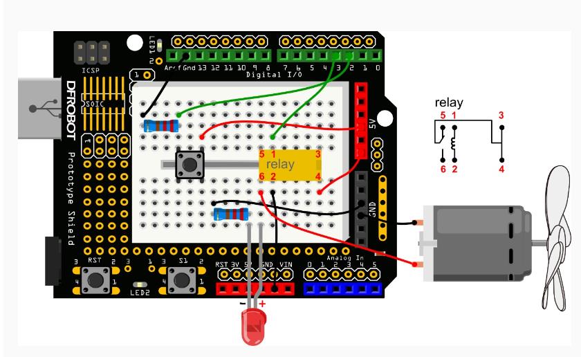
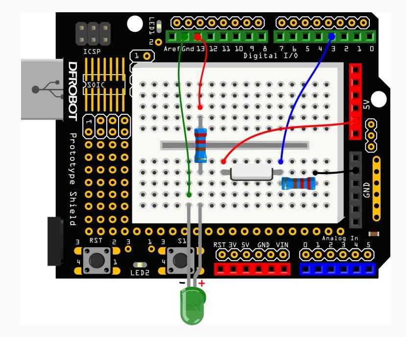
Button to control the fan
Wiring diagram
video
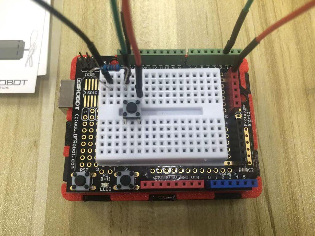
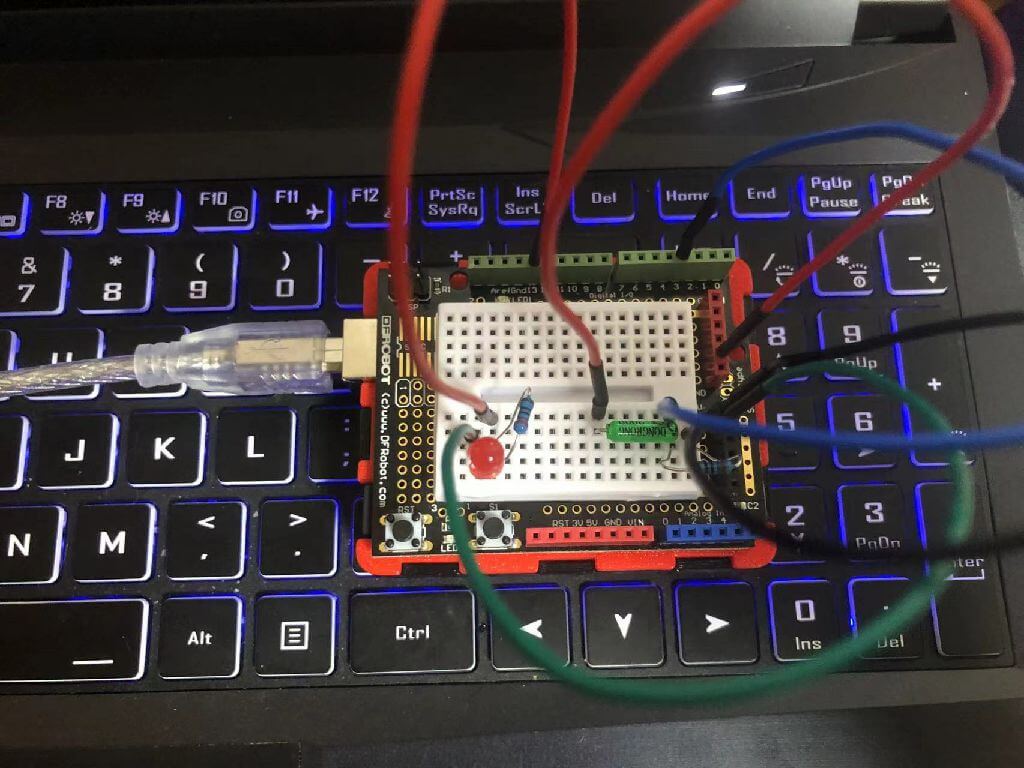
Install Button
1. Connect the 220R resistor.
2. Connect the resistor end to digital pin 2.
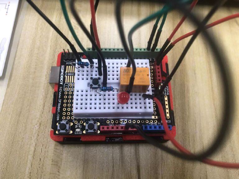
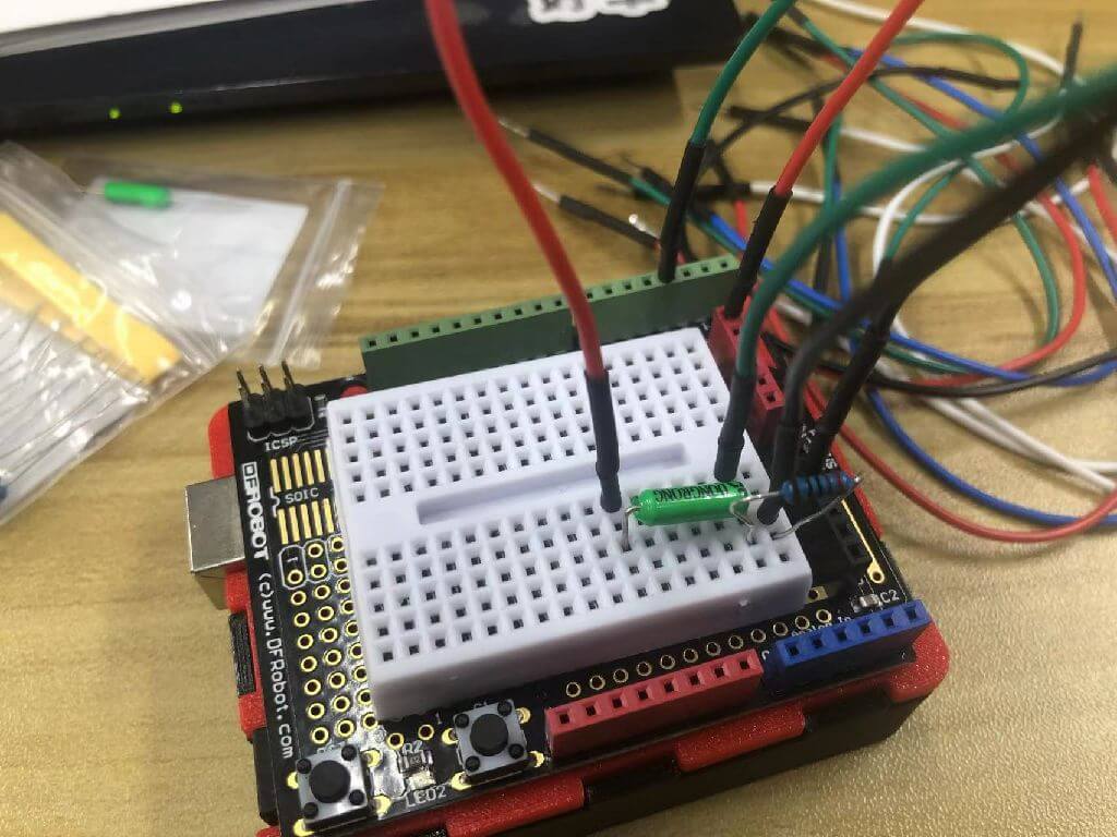
Install the small relay and red LED
1. Relay pin 1 is connected to digital pin 3.
2. Connect pin 2 of the relay to GND.
3. The positive pole of the LED is connected to pin 6 of the relay, the negative pole is connected to a 220R resistor and then connected to GND.
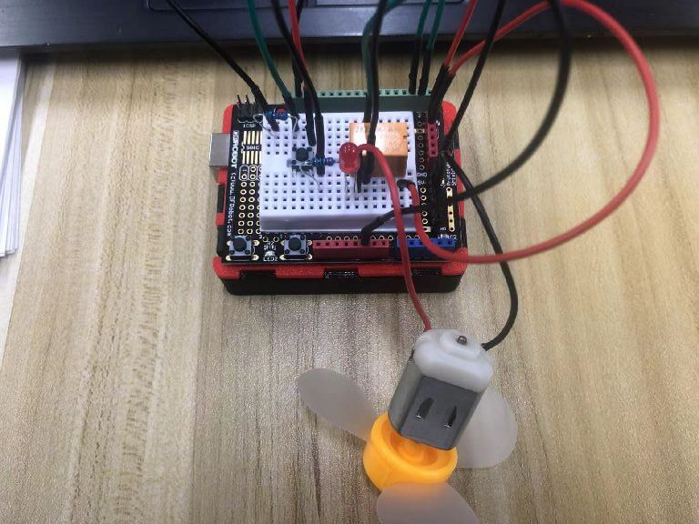
install fan
1. The positive pole (red wire) of the fan is connected to pin 6 of the relay.
2. The negative pole (black wire) of the fan is connected to GND.
The Code
          int buttonPin = 2;
          int relayPin = 3;
          int relayState = HIGH;
          int buttonState;
          int lastButtonState = LOW;
          long lastDebounceTime = 0;
          long debounceDelay = 10;

          void setup() {
                 pinMode(buttonPin, INPUT);
                 pinMode(relayPin, OUTPUT);

                 digitalWrite(relayPin, relayState);
          }

          void loop() {
                 int reading = digitalRead(buttonPin);
                 if (reading != lastButtonState) {
                             lastDebounceTime = millis();
                  } -
                 if ((millis() - lastDebounceTime) > debounceDelay) {
                        if (reading != buttonState) {
                                buttonState = reading;

                                 if (buttonState == HIGH) {
                                           relayState = !relayState;
                                 }
                         }
                   }
                   digitalWrite(relayPin, relayState);
                   lastButtonState = reading;
          }
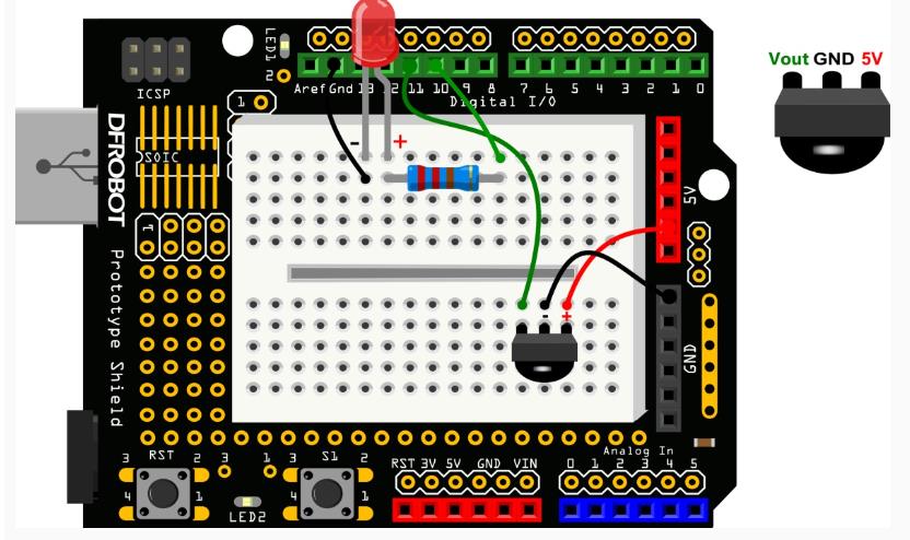
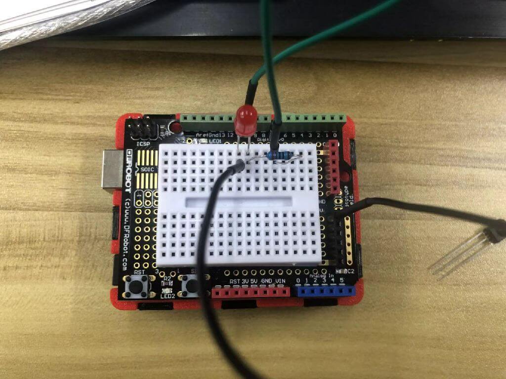
Vibration Sensor Light
Wiring diagram
achievement
Install the vibration sensor
Install the red LED
The Code
          int SensorLED = 13;
          int SensorINPUT = 3;
          unsigned char state = 0;

           void setup() {
            pinMode(SensorLED, OUTPUT);
            pinMode(SensorINPUT, INPUT);
            attachInterrupt(1, blink, RISING);
            }

           void loop(){
            if(state!=0){
            state = 0;
            digitalWrite(SensorLED,HIGH);
            delay(500);
            }
         else
           digitalWrite(SensorLED,LOW);

         void blink(){
         state++;
         }
Infrared remote control light
Wiring diagram
achievement
Install the red LED
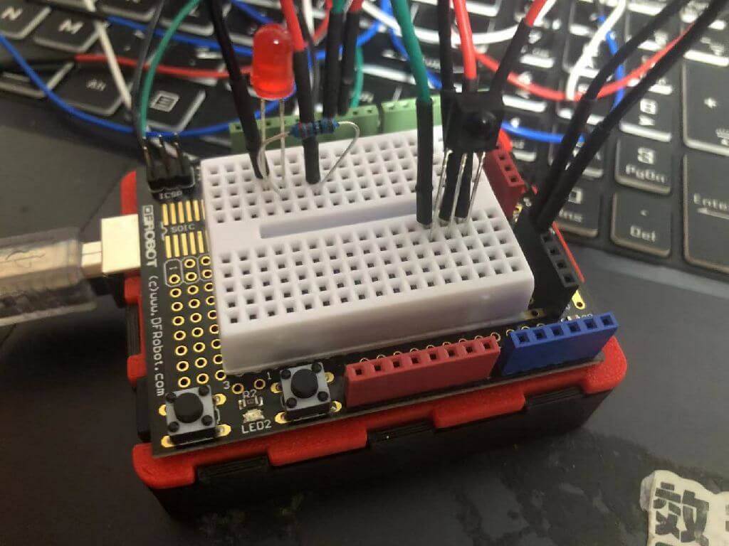
Install the infrared remote control
The Code
            #include
              int RECV_PIN = 11;
              int ledPin = 10;
              boolean ledState = LOW;
              IRrecv irrecv(RECV_PIN);
              decode_results results;

              void setup(){
                  Serial.begin(9600);
                  irrecv.enableIRIn();
                  pinMode(ledPin,OUTPUT);
              }

              void loop() {
                   if (irrecv.decode(&results)) {
                           Serial.println(results.value, HEX);
                      if(results.value == 0xFD00FF){
                              ledState = !ledState;
                              digitalWrite(ledPin,ledState);
                         }
                         irrecv.resume();
                     }
              }
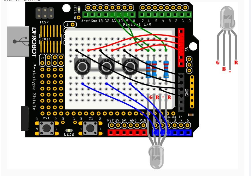
Potentiometer control a RGB LED
Wiring diagram
achievement
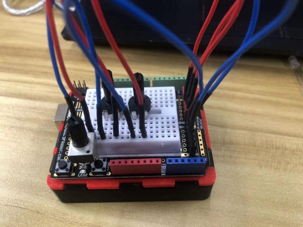
Install potentiometer
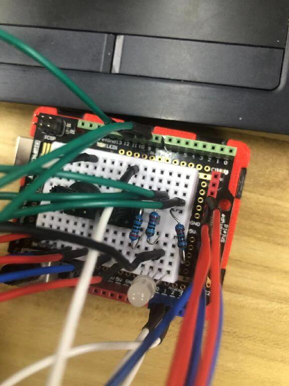
Install full color LED
          int redPin = 9;
          int greenPin = 10;
          int bluePin = 11;
          int potRedPin = 0;
          int potGreenPin = 1;
          int potBluePin = 2;

          void setup(){
              pinMode(redPin,OUTPUT);
              pinMode(greenPin,OUTPUT);
              pinMode(bluePin,OUTPUT);
              Serial.begin(9600);
          }

          void loop(){
             int potRed = analogRead(potRedPin);
             int potGreen = analogRead(potGreenPin);
             int potBlue = analogRead(potBluePin);

             int val1 = map(potRed,0,1023,0,255);
             int val2 = map(potGreen,0,1023,0,255);
             int val3 = map(potBlue,0,1023,0,255);

             Serial.print("Red:");
             Serial.print(val1);
             Serial.print("Green:");
             Serial.print(val2);
             Serial.print("Blue:");
             Serial.println(val3);

             colorRGB(val1,val2,val3);

            void colorRGB(int red, int green, int blue){
            analogWrite(redPin,constrain(red,0,255));
            analogWrite(greenPin,constrain(green,0,255));
            analogWrite(bluePin,constrain(blue,0,255));
          }
Mind+ Programming
I used DFROBOT's handpy to make a music playing device and a sound volume measuring device.
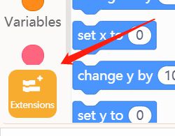
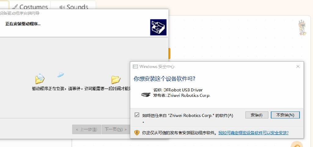
First go to the extension options in the lower left corner of the Mind+ software.
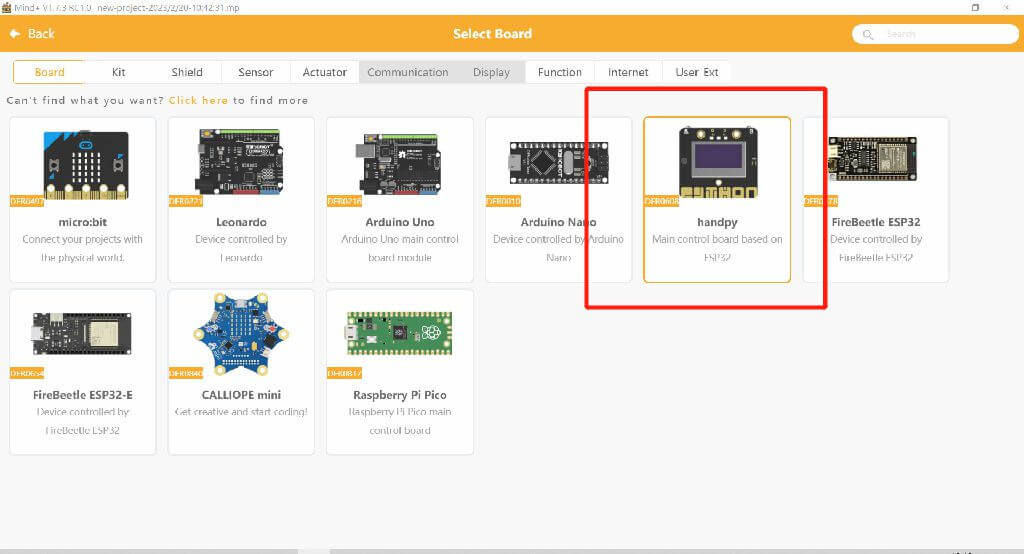
Select handpy in the extension options
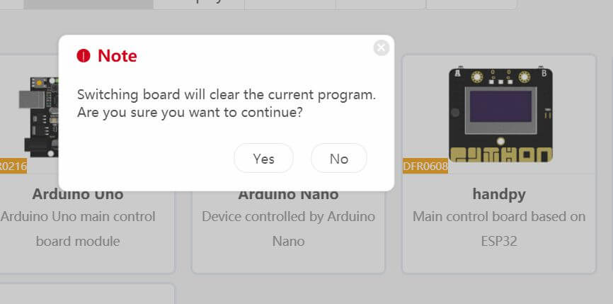
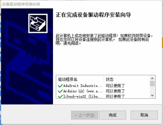
Select Yes
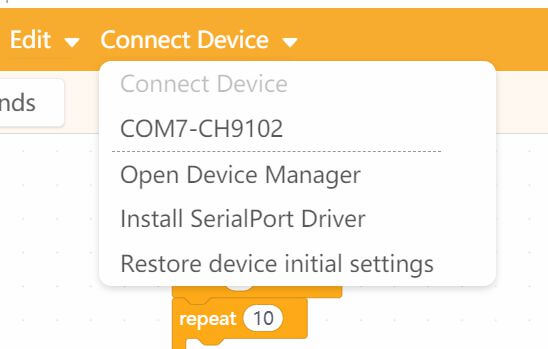
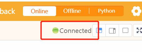
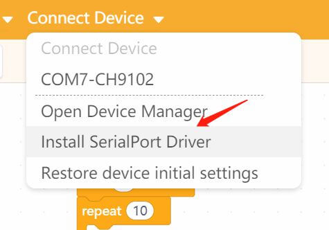
Select the serial port, the connection is successful
upload codes
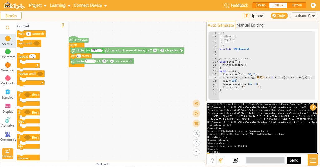
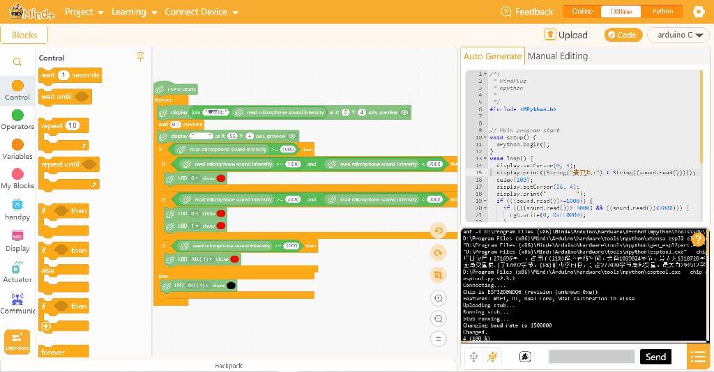
noise alarm
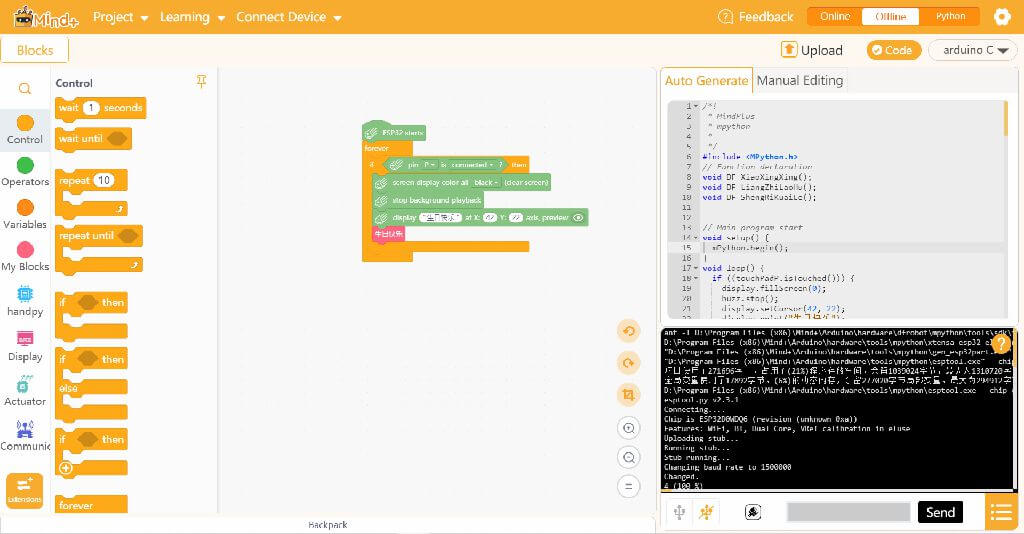
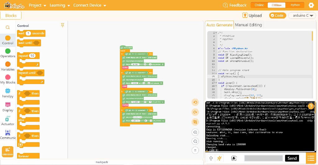
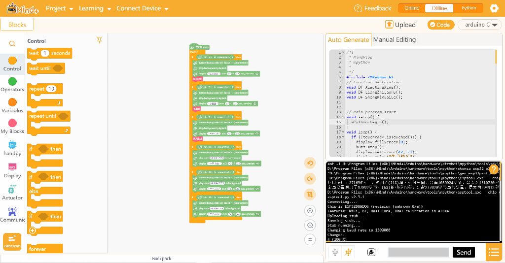
music controller
Error encountered
1. The fan switch has a delay and is not sensitive enough.
2. Infrared remote control cannot be used.
problem solving
1. The fan switch has a delay and is not sensitive enough.
1. Hardware problem
2. The button pins are very small, and the breadboard connection is not smooth, so it needs to be installed several times.
3. Reduce the jitter time