
The goal of this week's assignment is to use an output device with a microcontroller on a board that we have designed.
For this work we will use a new design that is a variation of the one used in week 08, it is a plate in the shape of Grogu but with an Attiny412 microcontroller and it is programmed via UPDI.
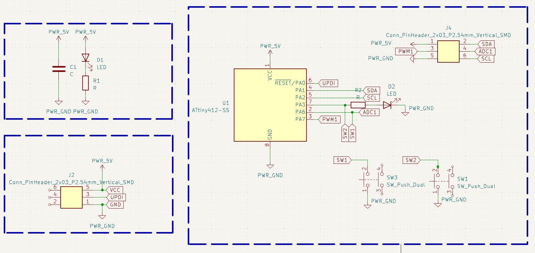
Figure N°1
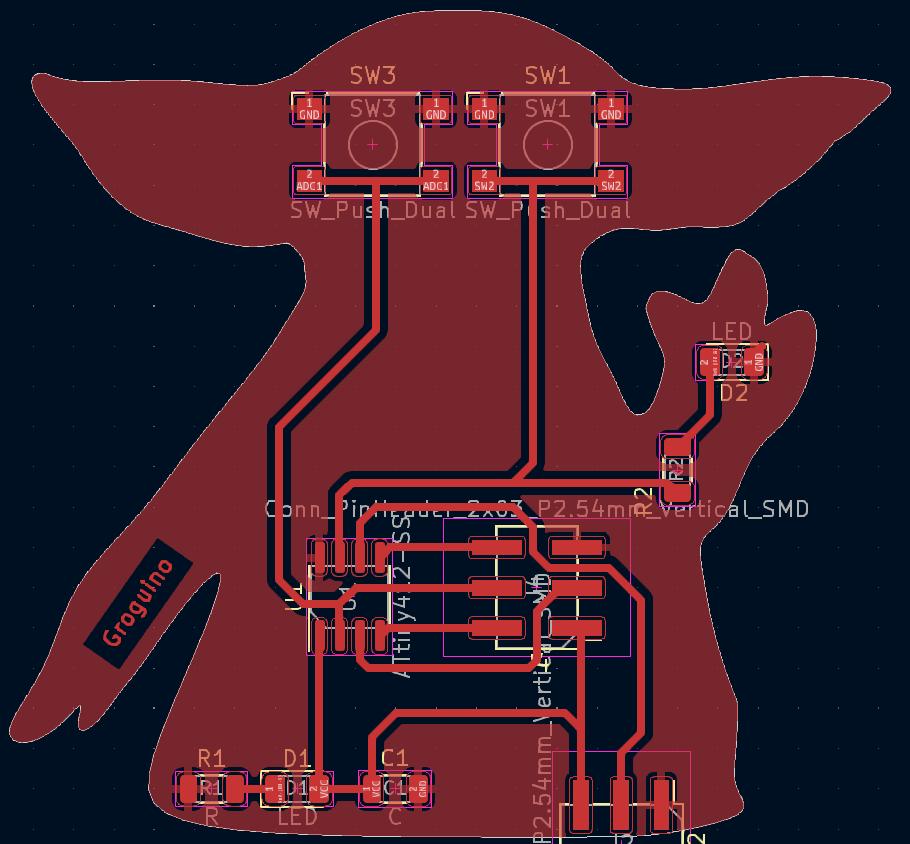
Figure N°2
We repeat the process carried out in week 8, milling the plate and cutting the contour.
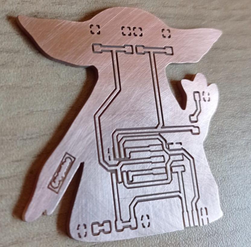
Figure N°3
Next we apply the anti-solder mask.
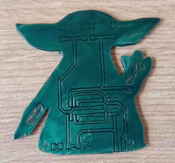
Figure N°4
We engrave the board with the laser cutter.
Video N°1
And this is the result.
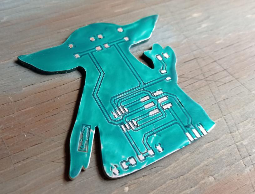
Figure N°5
Them we solder the components to the board.
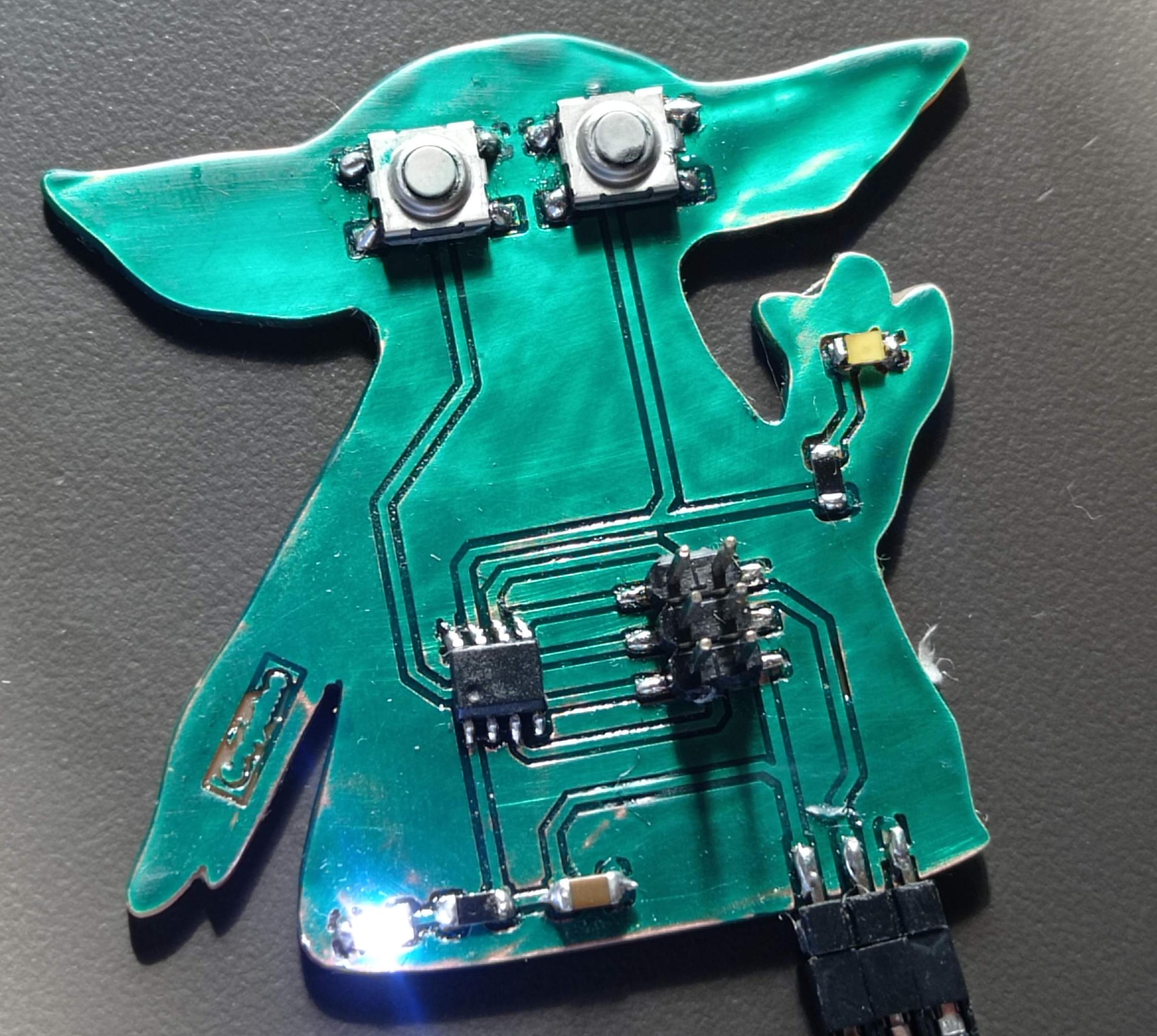
Figure N°6
To program via UPDI we follow the following steps:
The programmer we will use for this task is an Arduino Uno board.

Figure N°7
This would be the connection diagram between the UPDI programmer and the pcb.
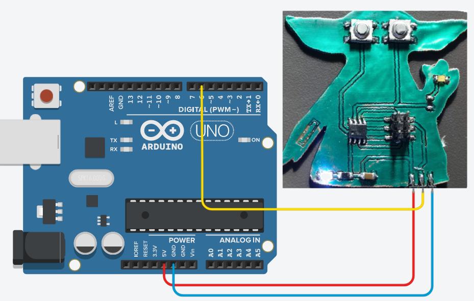
Figure N°8
We upload the classic Blink example to the board and see Grogu's hand blink.
Video N°2
In the same way we put a case that is shaped like his clothes.
Video N°3
Now we must place the output device on our custom PCB board, it will be a 20x04 LCD with an I2C adapter.
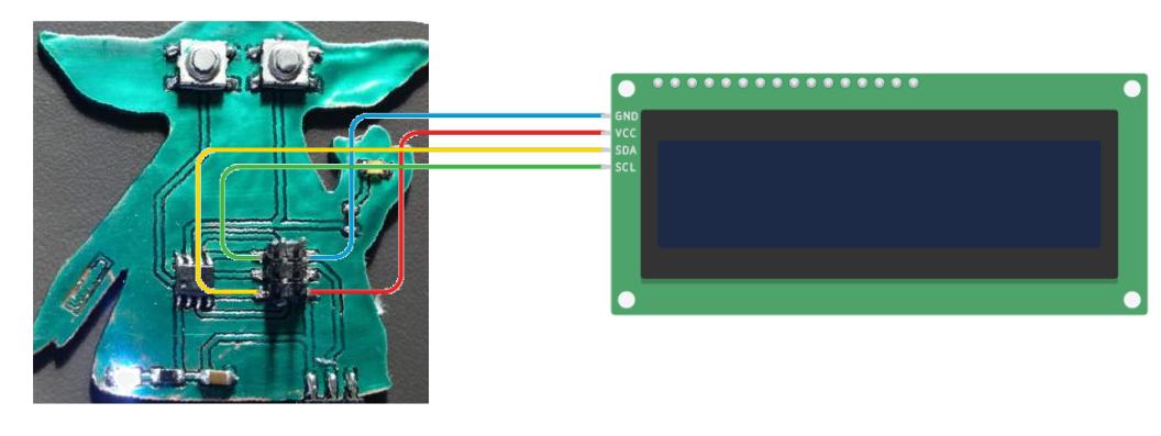
Figure N°9
The script to be used is similar to the examples of the "LiquidCrystal_I2C" library.
It is important to mention that each LCD screen has a hexadecimal address, for a 20x04 LCD the "0x27" is used.
Following the Star Wars theme, we will put a phrase on the LCD screen in the first lines of the LCD, additionally a small face that looks like grogu will be made.
                        #include <Wire.h>
                        #include <LiquidCrystal_I2C.h>

                        LiquidCrystal_I2C lcd(0x27,20,4);

                        void setup()
                        {
                          lcd.init();
                          lcd.init();

                          lcd.backlight();
                          lcd.setCursor(7,0);
                          lcd.print("May the force");
                          lcd.setCursor(9,1);
                          lcd.print("be with you ");
                          lcd.setCursor(2,1);
                          lcd.print("^ ^");
                          lcd.setCursor(1,2);
                          lcd.print("(o_o)");
                          lcd.setCursor(2,3);
                          lcd.print("Fab Academy 2023");
                        }


                        void loop()
                        {
                          digitalWrite(LED_BUILTIN, HIGH);
                          delay(100);
                          digitalWrite(LED_BUILTIN, LOW);
                          delay(100);
                        }
This is how the implementation looks.
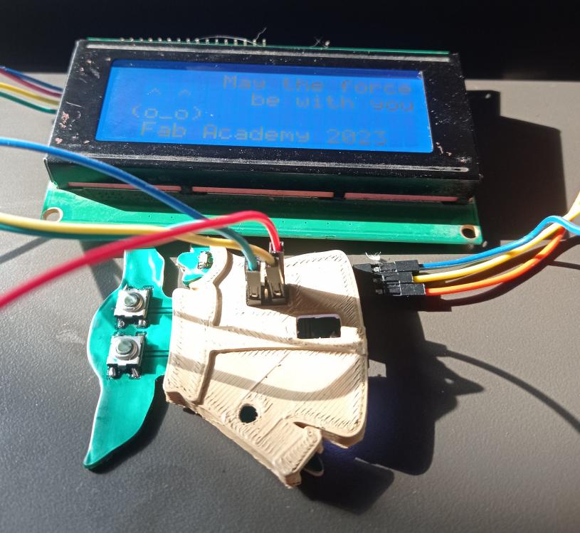
Figure N°10
And this is the message displayed.
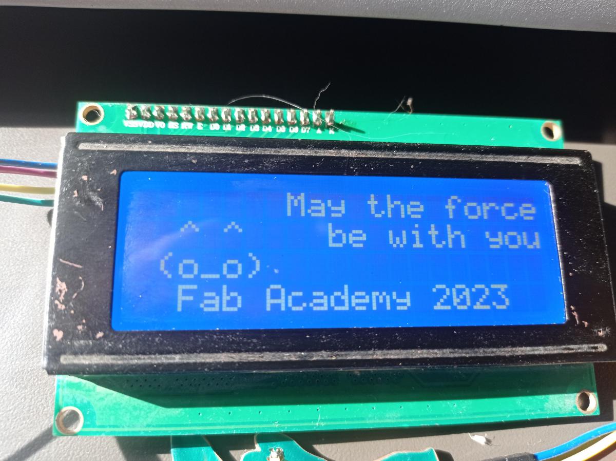
Figure N°11
For the group work we have to measure how much current our output device is consuming.
We are going to do 2 tests, one with the LCD screen and another without it, we will use a stationary power supply since the current taken by the PCB is shown.

Figure N°11
In the first test we see that the consumption of the board alone is 0.02 A or 20 milliamps (mA).
Video N°4
In the second test we repeat the same action but with the LCD screen connected to the microcontroller, showing that in this test the consumption is 0.07 Amps or 70 milliamps.

Figure N°12
Video N°5
With these two tests we see that the difference in current between the two is 50 milliamps, so that is the consumption of our output device.
The files created or used this week can be downloaded here:
| Grogu PCB v2 with AtTiny412 - Kicad Files | Link |
| Grogu PCB v2 with AtTiny412 - traces | Link |
| Grogu PCB v2 with AtTiny412 - outline | Link |
| Grogu PCB v2 with AtTiny412 - mask | Link |
| Script LCD 20x04 | Link |