
This week's assignment is to make a 2D design for production using a CNC machine.
The first step to use this type of machine is to have safety training for this space and the tools we have at hand.

Figure N°1
The first item that we take into account to do a CNC machining is the drill bit, in this case we find it with a caliber much larger than what we need, to make a change of drill bits, 2 keys are used. The one we will use is a 32mm.
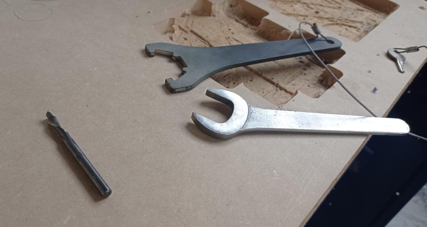
Figure N°2
We see a comparison between the two, it is important to highlight that the orientation of the milling cutter since depending on it the remaining shavings can remain at the bottom or on top of the wood. In addition to having an air filter we can minimize this residue to a large extent. In this case we will use a downcut type milling cutter.
The turning speed of the milling cutter is 14,000 RPM recommended by the supplier. In the laboratory, tests were carried out increasing or decreasing this value where it was observed that higher rpms cause the milling cutter to break and less ones did not cut correctly. The travel speed recommended by the supplier is 2000 RPM to have the result in adequate time, a lower speed makes it take a long time to make the cut and a higher speed breaks the cutter.
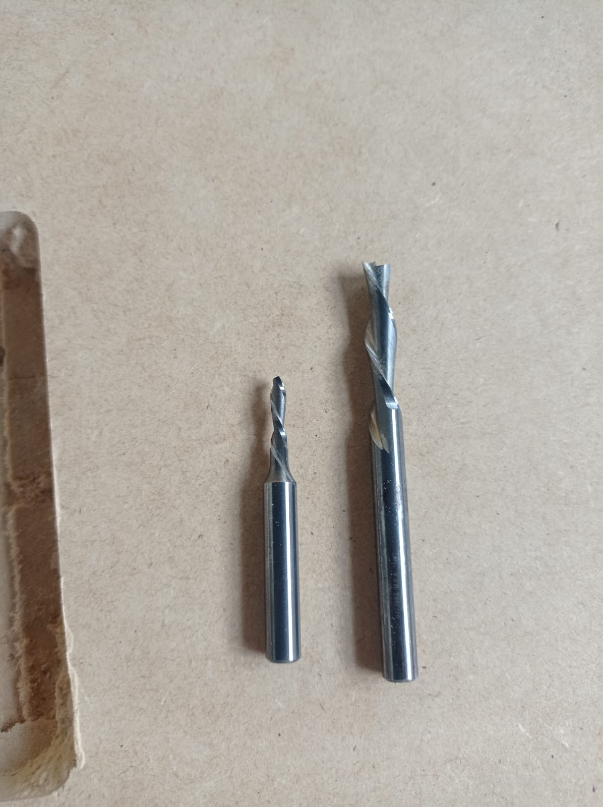
Figure N°3
The next step once we have the bit installed is calibration. For this, the piece of wood must be previously secured, in our case we use self-tapping screws with an automatic screwdriver at the ends.
For the Z axis there are 2 pieces, a crocodile and a metal plate.
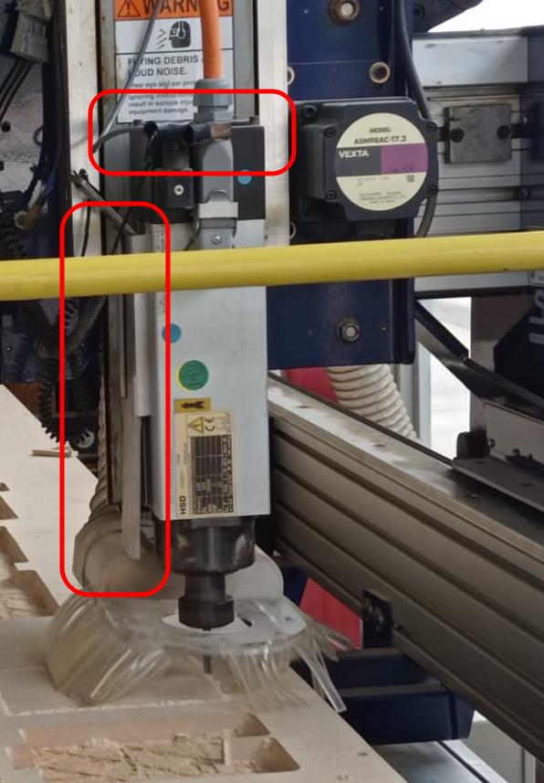
Figure N°4
When the plate is placed in the lower part of the table and the crocodile in the axis structure, we go to the Shopbot software, there we have the "Zero axes" button that, when activated, will make the cutter go down until both parts detect electrical continuity. In the case of the XY axes, these are adjusted automatically with limit switches.
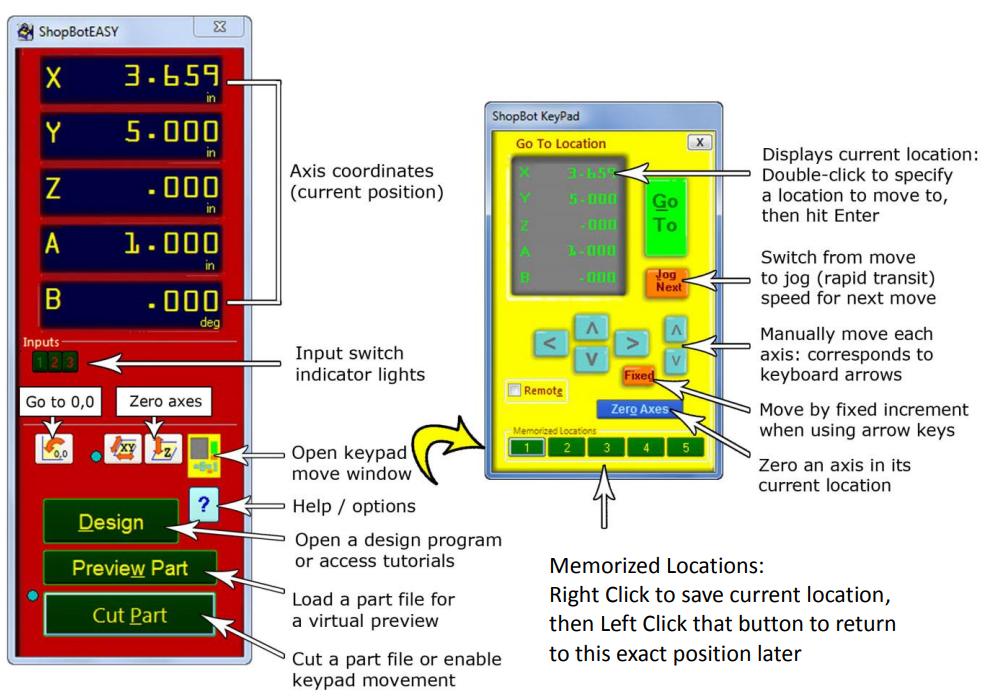
Figure N°5
Before putting the machine to work, the machine must turn on the air filter, it is together with the cutter and they make a lot of noise that can harm human hatred, so we must wear safety earmuffs, also in case any splinters come out shooting in the cut is necessary to wear safety glasses.

Figure N°6
It is also important to know where the emergency stop buttons are located, on the right side of the machine we have one.
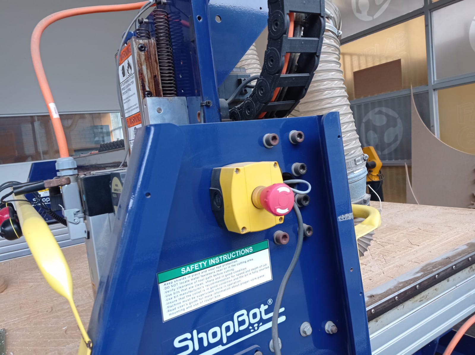
Figure N°7
And the other is on the side of the computer that sends the file to be cut.

Figure N°8
The first file we send to fabrication is to find the kerf of the machine. We will do 2 of them and we will see how they press and fit together. This design was made in Fusion 360 and you can download it here.

Figure N°9
Then we go to the Vcarve Pro software, the first thing here is to define the width of our table, which is 2440mm x 1520mm and the thickness of our plates will be 15mm.
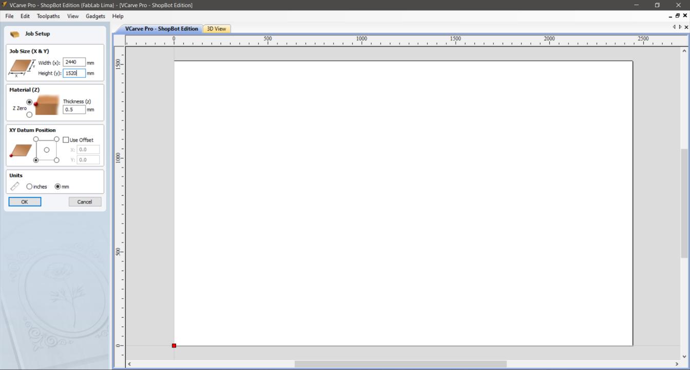
Figure N°10
Then we import the vectors, in this case our file is in .DXF format.

Figure N°11
There are many parameters that we must configure and we are going to detail each one of them. A relevant aspect is the internal corners of our design, since we have a drill with a thickness that makes it difficult to make 90 degree corners, for this Vcarve Pro offers us the option of using Fillets, these add circumferences to our corners so that the corner shape is maintained. For this example we use the Dog-Bone type.

Figure N°12
We then set the depth of cut to be 16.3mm to make sure it cuts even sections that are bowed. As the manufacturer recommends, several passes will be made to reach this depth, specifically 3 passes.
We also choose the drill bit, as we previously mentioned we will use a 32mm or 1/4 inch one, the speed with which it will rotate is 14000 RPM.
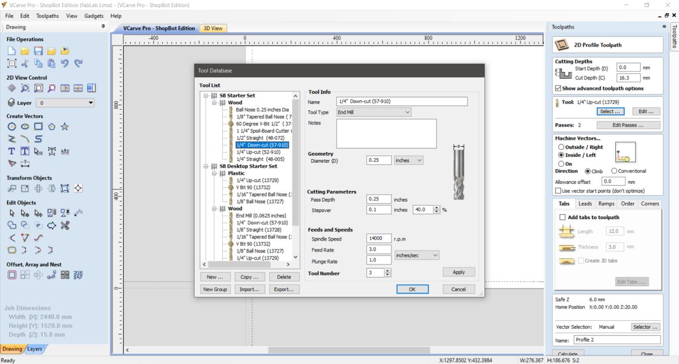
Figure N°13
Next we have the option of passing the drill bit internally and externally, as it is a figure without holes it will be an external one. The tabs are small parts that are not completely cut to maintain the stability of the plate while the cut continues, for this example we will place 1 on each piece.
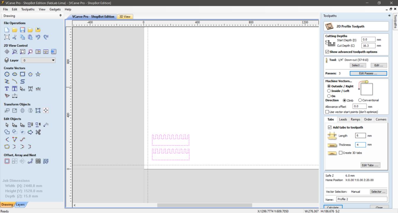
Figure N°14
Finally we get a preview of the route that the machine will take to manufacture the part.
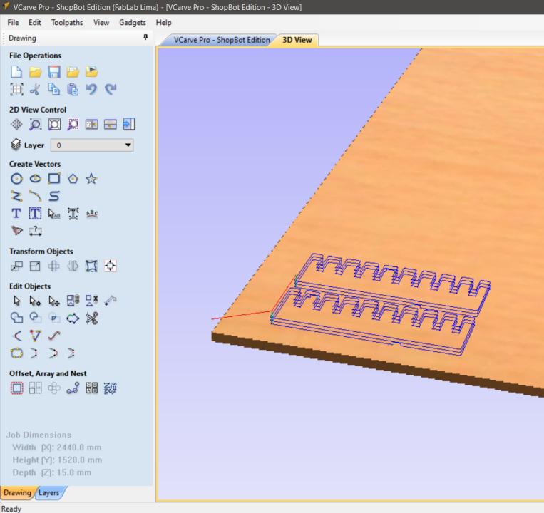
Figure N°15
The cut was made correctly and we have the result.
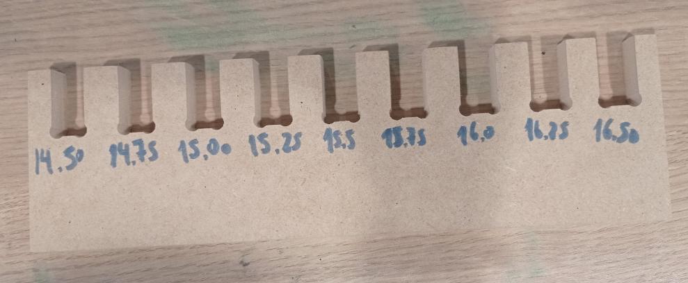
Figure N°16
If we are strict when we use a gap of 15.25 (+0.25 of the thickness of the piece) it fits quite well, so much so that it is difficult to separate it again. That is why we choose 15.50 so that it is firm but not impossible to separate the parts.
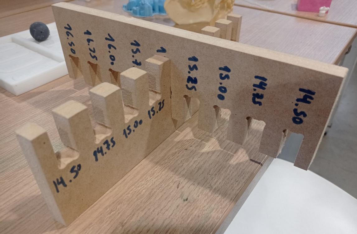
Figure N°17
Now we have the goal of make something big.
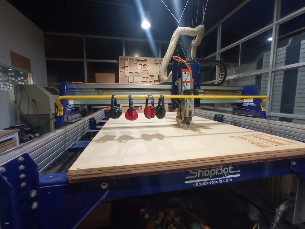
Figure N°18
We repeat all the configuration, calibration and follow instructions previously described, not forgetting to protect your ears.

Figure N°19
In this case we are going to make an exercise wheel for cats. The design was also made in Fusion 360 based on a circumference of 32 vertices, then a rectangle was created to use the "circular pattern" tool which allows us to select these edges and a pivot point, with this we create 32 copies of this rectangle In each of these sections, a space was placed that will be the joint for the steps, taking into account the previously found kerf.
The result was exported in DXF format. The main circumference and steps can be downloaded here.
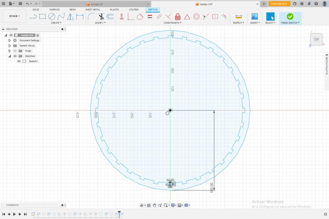
Figure N°20
So the first step will be to make one of the circles and 3 steps to verify how they fit between them. We import the designs in Vcarve and set as the previous example.
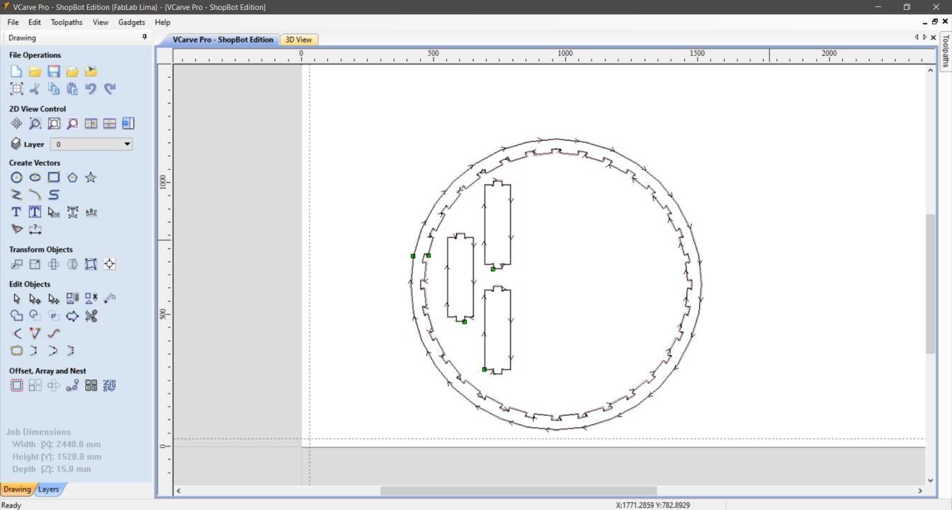
Figure N°21
We see the preview of the route.
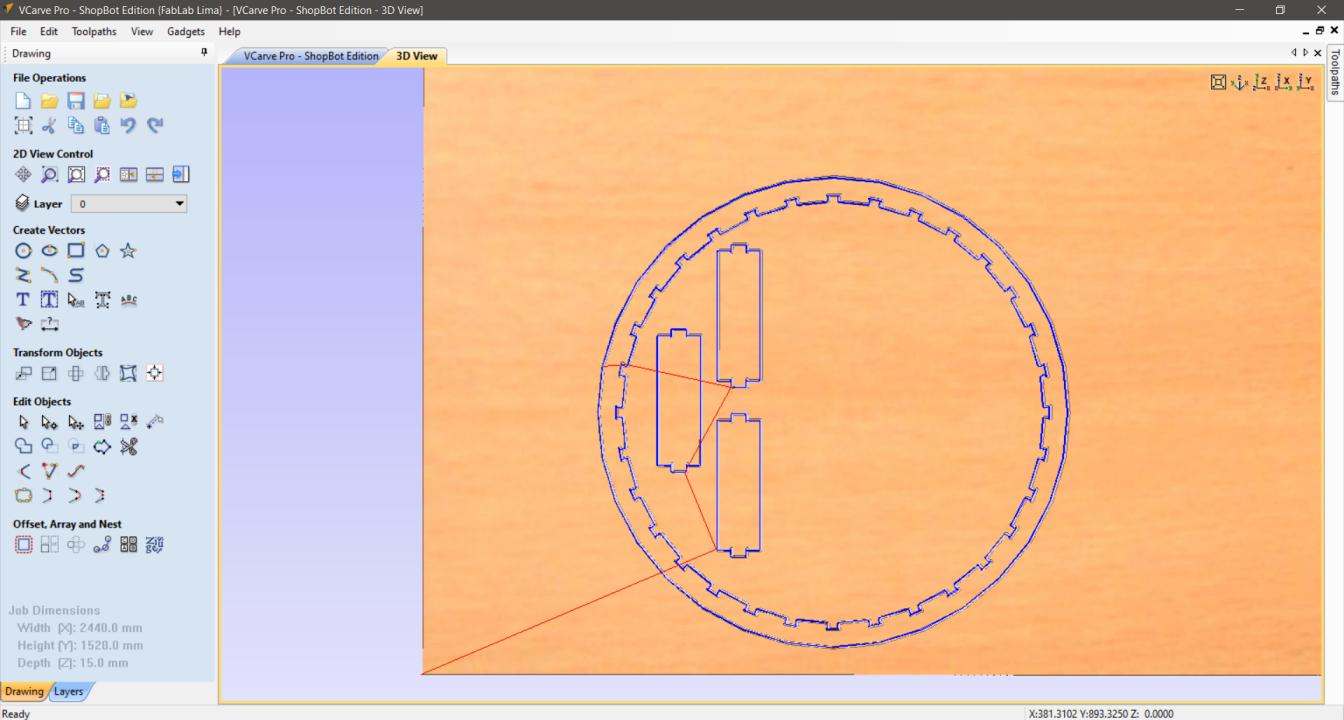
Figure N°22
The machine starts its journey.
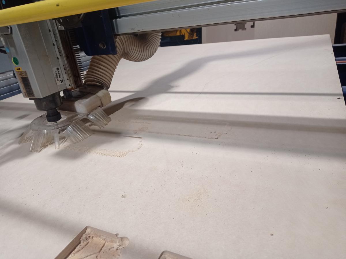
Figure N°23
By having to make 3 passes for each part, the time is longer.
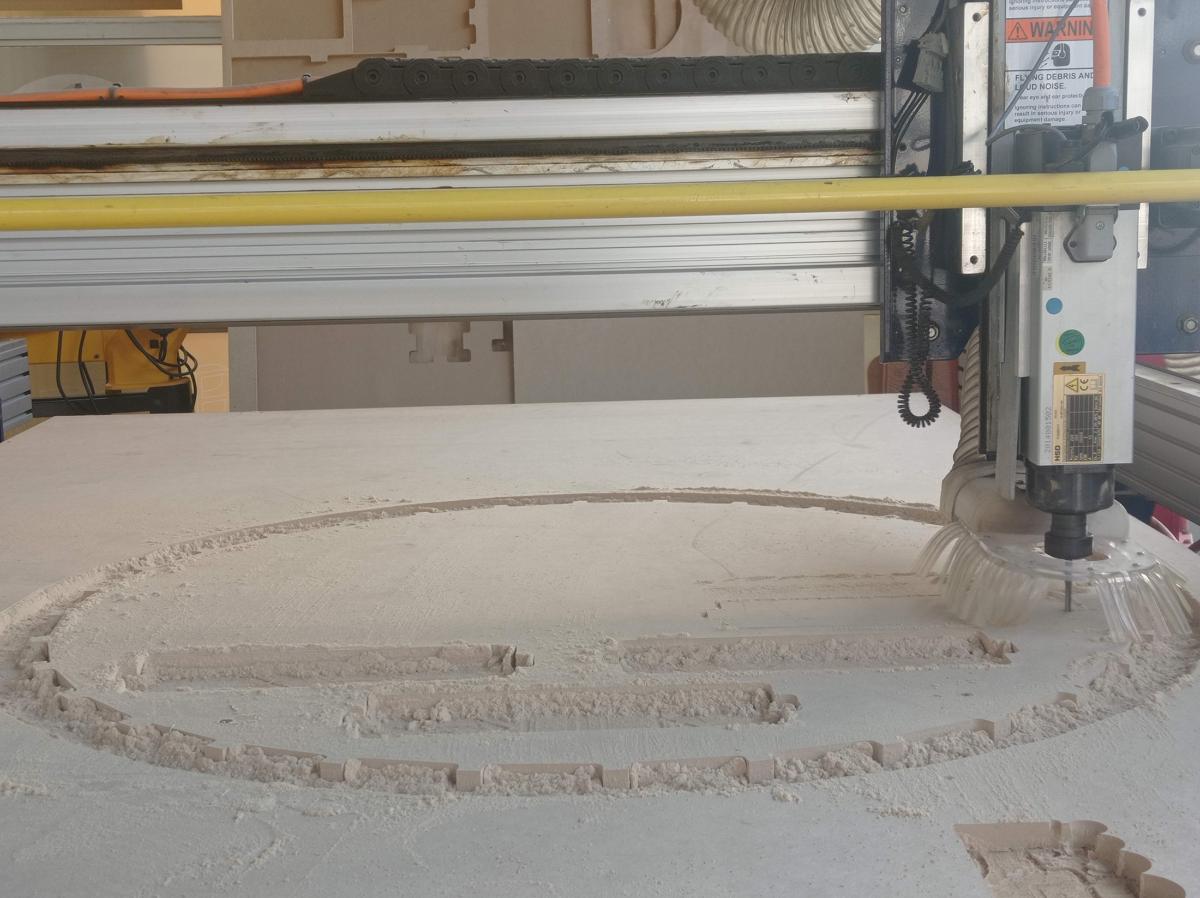
Figure N°24
Finally, when finishing cutting the parts, the tabs must be removed and the lower part must be sanded.
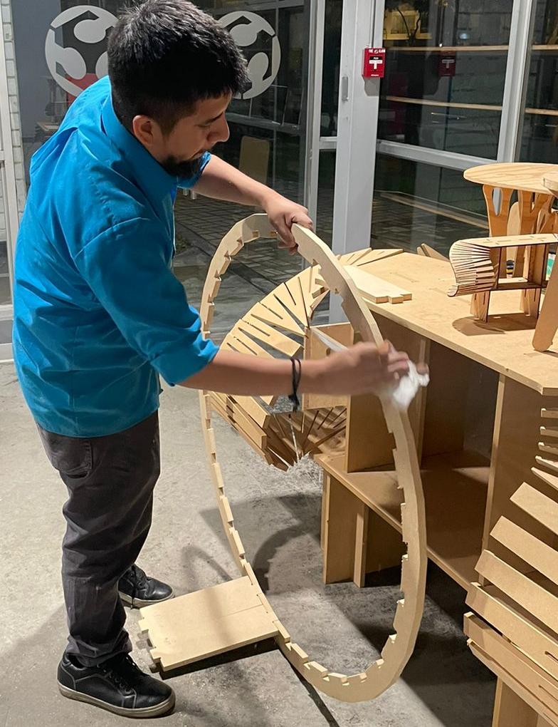
Figure N°25
We see that the steps fit perfectly with the circumference but between them they leave a small space of 2.8mm. Therefore we will modify the file adding 1.35mm to each side of the step and minimize the space between them.
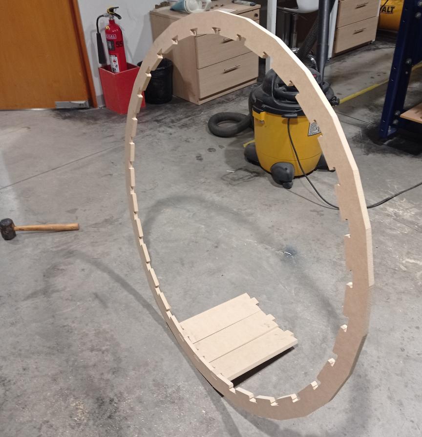
Figure N°26
As we want to optimize the material we have, we will continue working with the same MDF sheet. We used both the inner space that was left of the circumference and the outer part to make these 32 pieces.
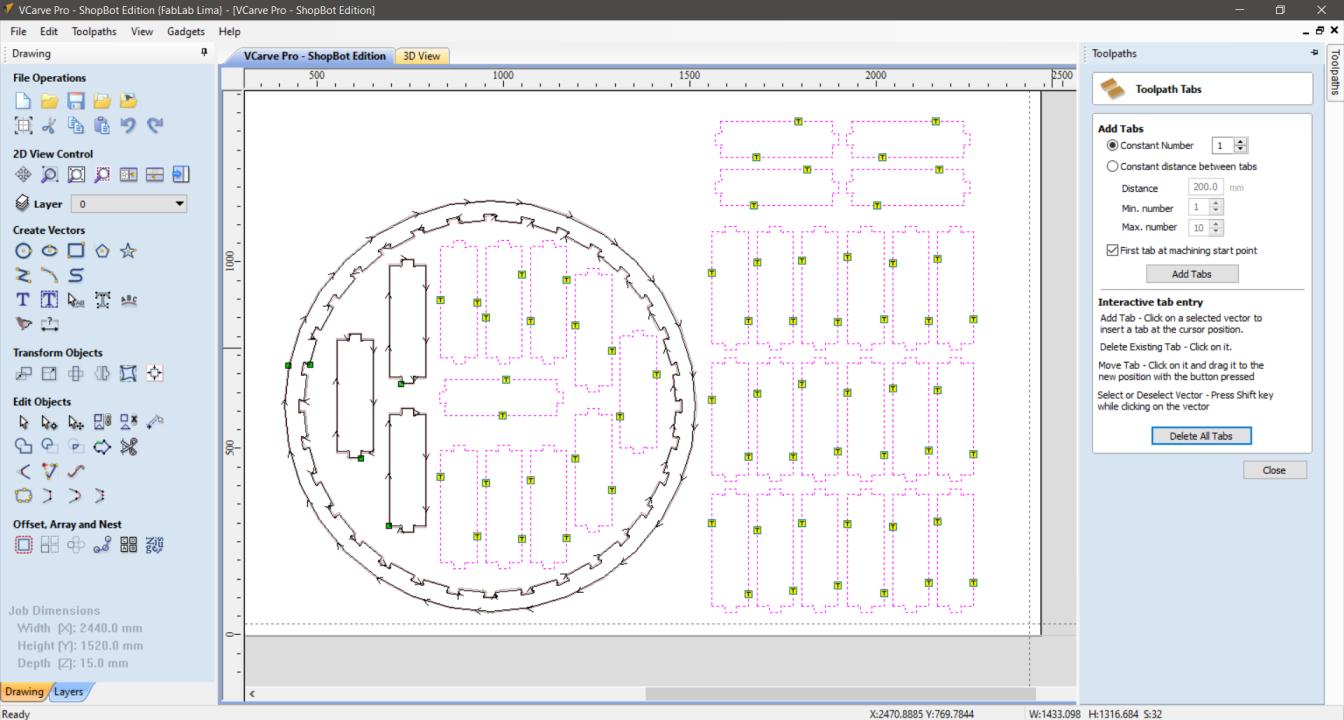
Figure N°27
We see in the preview that the route will only be in the parts that are intact from the last cut.
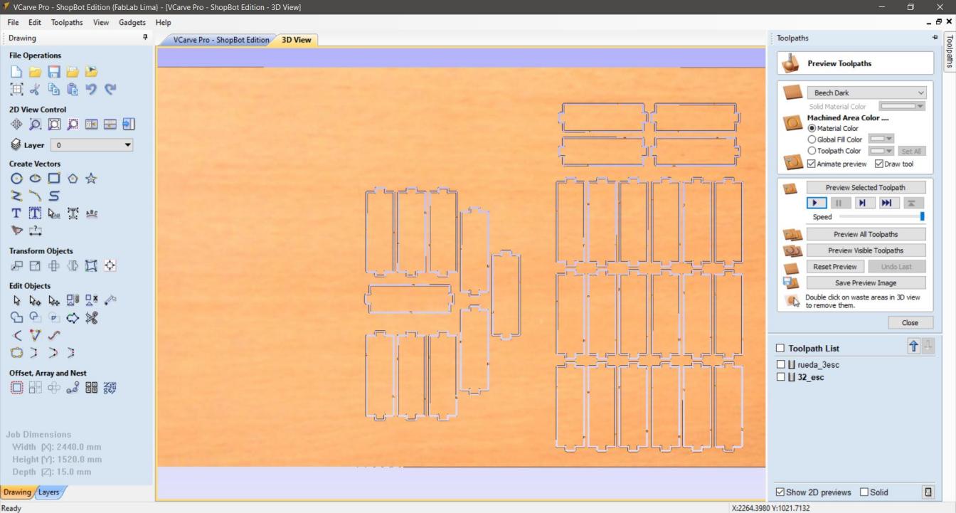
Figure N°28
Almost an hour of cutting later, this is how the remains remain.
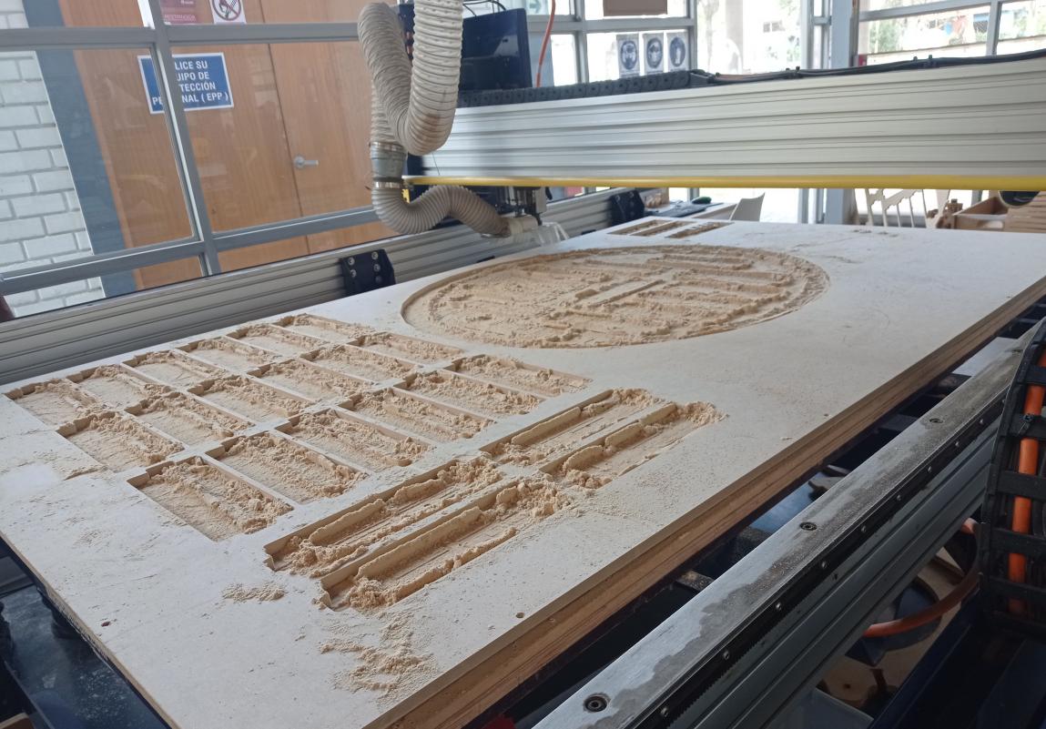
Figure N°29
And this is the residue of the inner part of the circumference, we leave almost no room for anything.
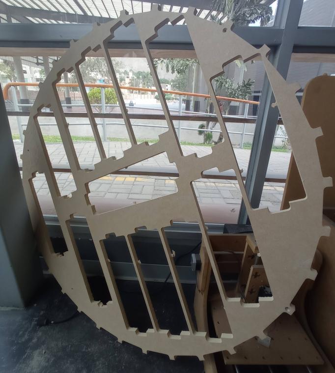
Figure N°30
To complete this design we must have a base that supports the wheel.

Figure N°31
In the same way, the design of this base in .DXF format can be downloaded here.
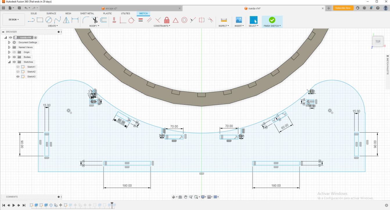
Figure N°32
Now we will cut the second circle with the bases and the sections that support it. Here it is important to mention that since we have internal parts we must make 2 cutting files, one for internal elements, here the movement mode of the drill must change to Inside. Then for the contours we use the Outside again.

Figure N°33
We see that there are 2 different cuts to build these parts.

Figure N°34
While the machine is cutting we are assembling what we already have ready.
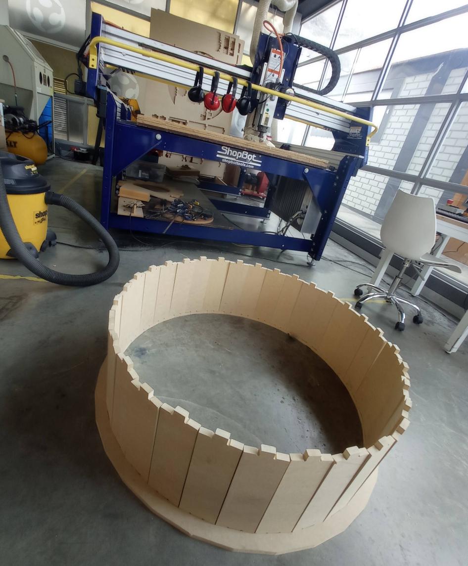
Figure N°35
Finally we start to assemble the parts, we see that now the steps of the wheel do not leave any space since we modified the original file.
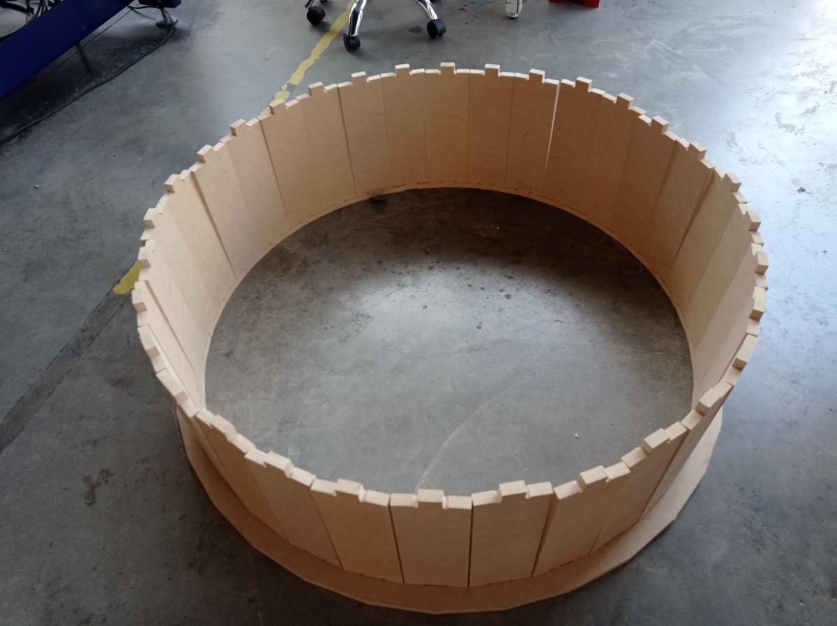
Figure N°36
Having all the pieces ready with the help of a rubber hammer we are going to place the second circumference.
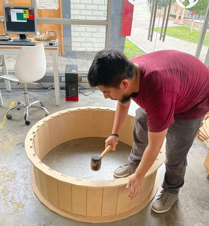
Figure N°37
And so the assembly has been excellent!

Figure N°38
In the same way, the base that supports the wheel has fitted perfectly.

Figure N°39
In the inner part, it will later have bearings that will allow the main wheel to rotate.

Figure N°40
And this is how the wheel for cats finally turned out, we did something big!

Figure N°41
The files created or used this week can be downloaded here:
| Kerf | Link |
| Wheel Circle | Link |
| Wheel Step | Link |
| Wheel base | Link |
| Wheel Connector 1 | Link |
| Wheel Connector 2 | Link |