4. Electronics production
This week I immersed myself in the world of etching PCB, soldering surface mounted components and blink LED on a circuit.
My assignments for this week were :
Group assignment:
- Characterize the design rules for your in-house PCB production process: document feeds, speeds, plunge rate, depth of cut (traces and outline) and tooling
- Document the workflow for sending a PCB to a board house
- Document your work to the group work page and reflect on your individual page what you learned
Individual assignment :
- Make and test a microcontroller development board
Group Assignment💡
Please follow this link for the group assignement documentation.
Individual Assignment💡
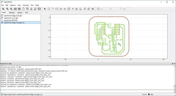
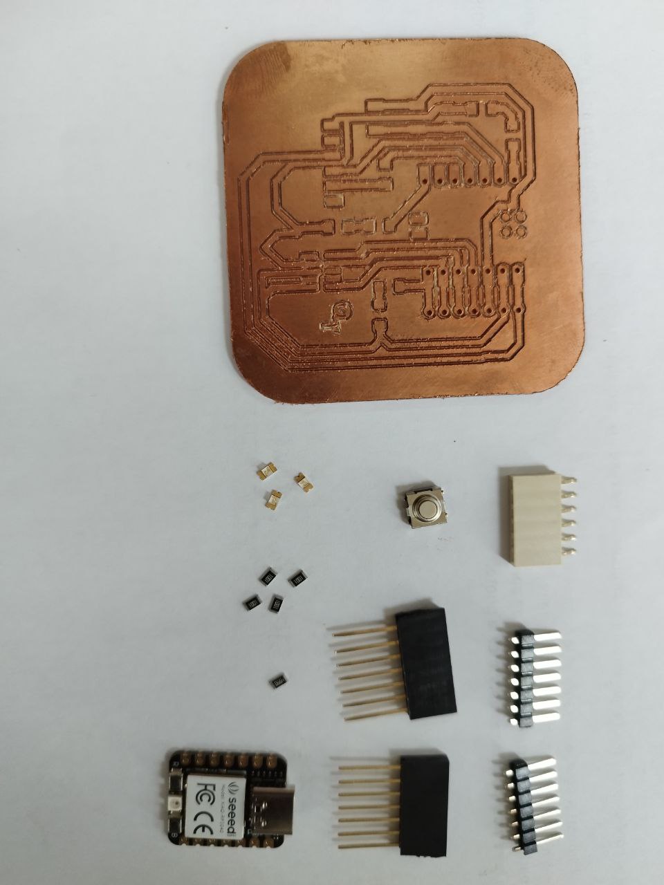
Base on the work of Quentorres-by Adrian i try to cut my first PCB.
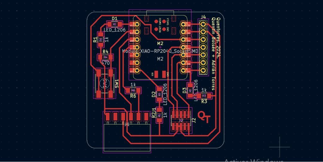
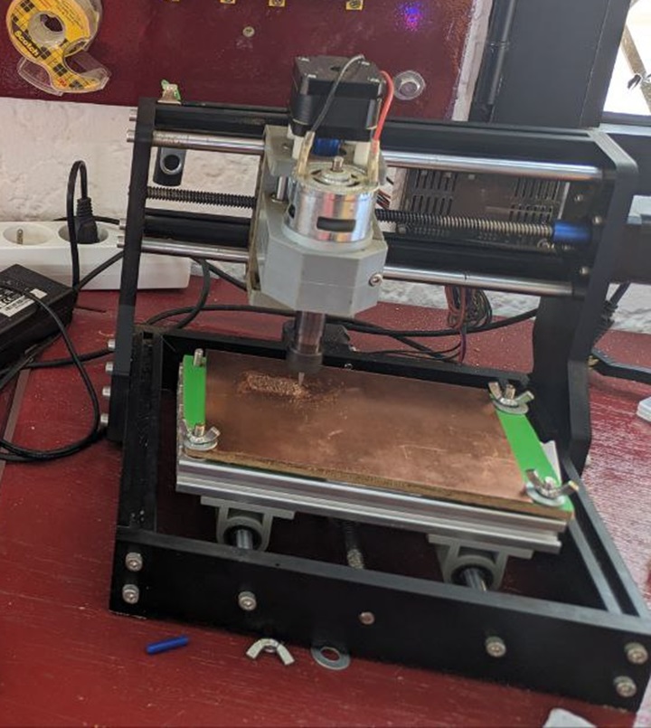
Milling PCB
I had to use the following parameters :
PCB Isolation Routing V-Bits
PCB: CutOut tool End Mill
PCB Hole tool Drill
Bit Type: V-Bit
flat-end Mill
Drill
Bit Size: 0.3 mm
1.16 mm
0.8
cut depth: -0.1
-0.4 mm
-1.8 mm
max depth: -0.1
-1.8 mm
-1.8 mm
cut speed: 4 mm/s
4 mm/s
4 mm/s
Plung speed: 4 mm/s
4 mm/s
4 mm/s
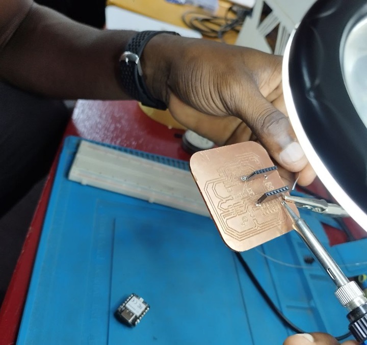
Soldering
Knowing the adventure that awaits me in the Fab Academy with soldering SMD PCBs, I decided to practice soldering with an SMD soldering kit using soldering with a soldering iron and also with soldering iron and liquid tin.
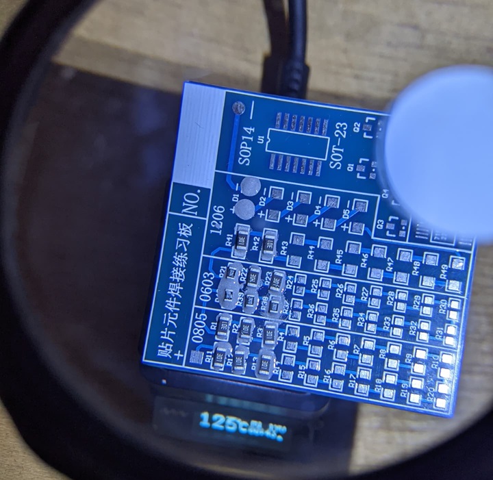
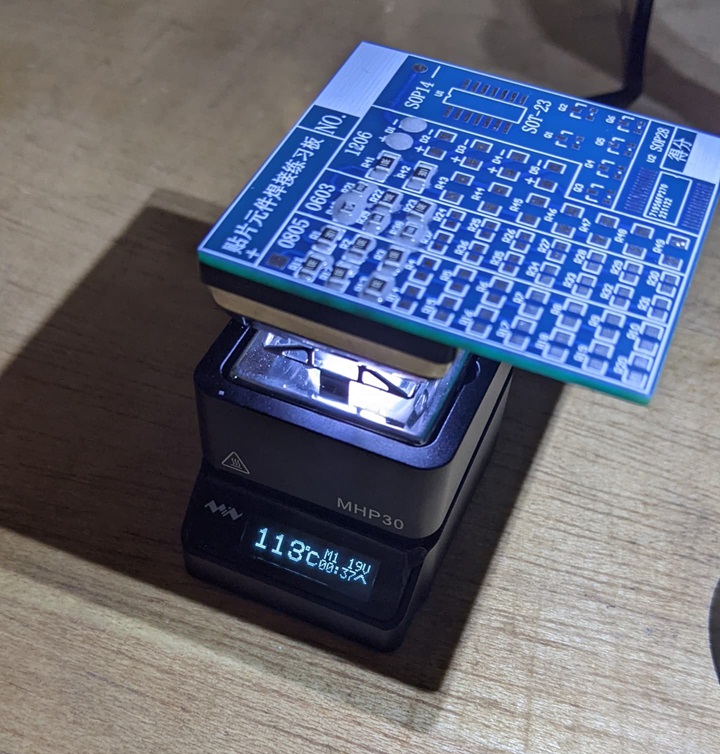
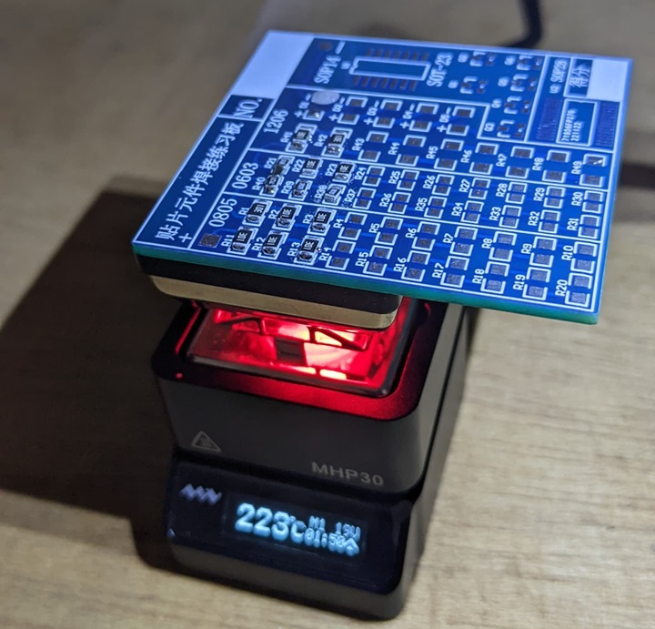
Then I applied his knowledge to my project.


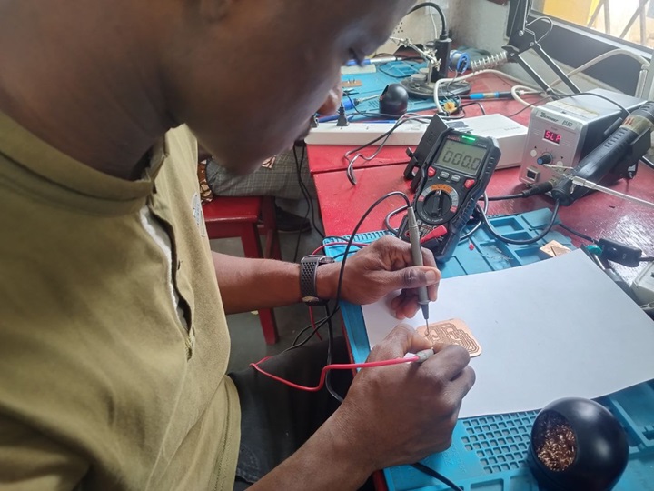
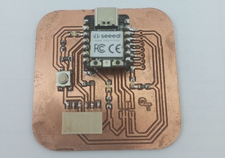
Code Example
I had to test this code to make an LED blink. The led is connected to PIN 26
void setup() {
  // initialize digital pin 26 as an output (pin26).
  pinMode(LED_BUILTIN, OUTPUT);
}

void loop() {
  digitalWrite(26, HIGH);   // turn the LED on (HIGH is the voltage level)
  delay(1000);                       // wait for a second
  digitalWrite(26, LOW);    // turn the LED off by making the voltage LOW
  delay(1000);                       // wait for a second
}