WEEK 9: Output Devices
INDIVIDUAL ASSIGNMENTS
This week I have to create my own PCB integrating an output. I have chosen to put a display since my final project is going to have one. Also since I have to make the PCB I am going to think about Networking & Communications week and integrate it on my board.
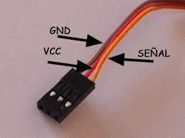
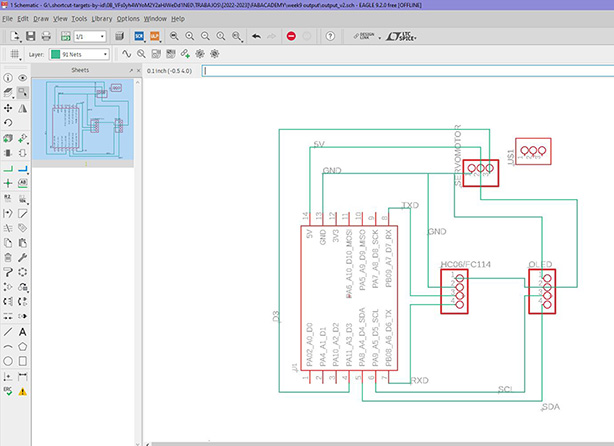
I am going to connect a servo motor to pin D3. The servo motor connector is 3 pins. The brown is GND, the Red 5V and the yellow is the one that would have to go to pin D3 of the xiao. The servo motor would be an SG90.
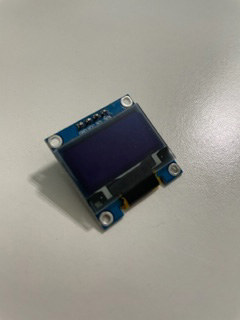
For the display I am going to use a 0.96 inch oled display. The display connector is a 4 pin connector. Gnd to gnd, VCC to 5V, SDA to D4 of the xiao, SCL to D5 of the xiao.
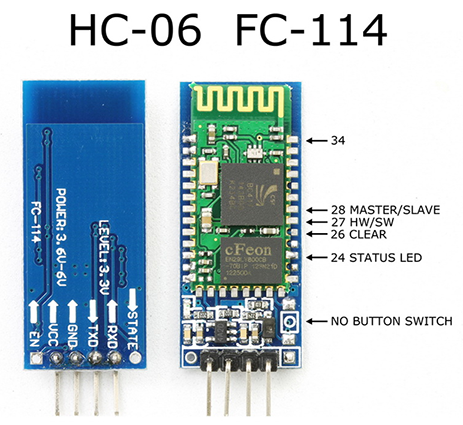
And for communications I am going to put a HC06. The HC06 communicates by serial port with the xiao, the lines have to be crossed RX from one to TX from the other. It is a 4 pin connector. VCC to 5V, GND to GND, TX from hc06 to D7 of xiao, RX from HC06 to D6 of xiao.
I have documented myself on the datasheet how I should connect the components properly In an Eagle file I have created a sketch of the PCB board.
Then I have created a swich board where I have been placing the components and joining the tracks, making sure that they do not cross each other.
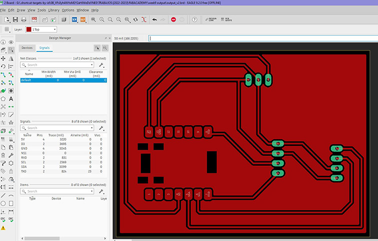
Then I saved it as a PNG and went to Photoshop to set the resolution to 1000 and the color mode to grayscale. Then I will save it as a .bmp file so I can import it into Dr. Engrave. If I have to change to other measurements I don't know what I have to base it on to put correct measurements.

Before starting to manufacture, the machining tool must be selected and the machine must be calibrated (xyz). For this step, the steps explained in the electronic manufacturing exercise have been followed, using the V-Panel software. The milling cutters used are 0.1 mm, cylindrical for cutting and conical for engraving.
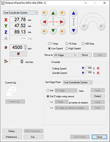
Then you have to import the design into the DR Engrave program, set the appropriate dimension and prepare the paths as in the previous exercise. I used the values of -0.10 mm for engraving and 1.60 mm for cutting. The other parameters of rotation speed and displacement are the same as in previous exercises. Once the engraving is launched the outer cut must be launched and wait for it to finish.
Once milled, I solder the components.
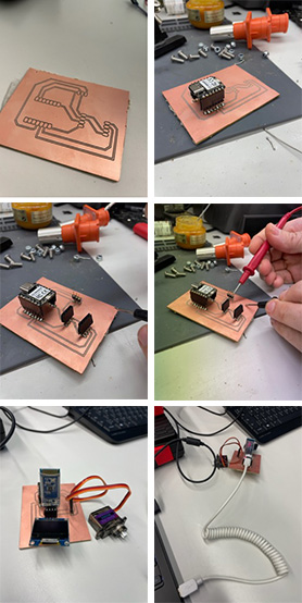

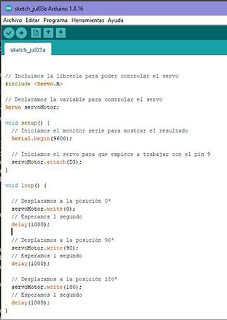
Below, I show the code I am going to use for the servo motor and the microcontroller. It is also available for download
This Arduino code controls a servo motor and performs movements in three specific positions: 0 degrees, 90 degrees, and 180 degrees. Below, I provide you with a line-by-line description of the code:
#include
Servo servoMotor;: A variable called "servoMotor" of type "Servo" is declared here. This variable will be used to control the servo motor.
Serial.begin(9600);: This instruction starts the serial communication at 9600 baud rate. It is used to display results or debug information through the serial monitor.
servoMotor.attach(D3);: The D3 pin of the Arduino is configured to control the servo motor. The servo motor is physically connected to this pin.
14-23. The code inside the loop() function is executed repeatedly in an infinite loop:
servoMotor.write(0);: Moves the servo motor to position 0 degrees. The value 0 indicates the initial or extreme left position of the servo.
delay(1000);: Waits 1 second before continuing.
servoMotor.write(90);: Moves the servo motor to the 90 degree position, which is the center position.
delay(1000);: Wait 1 second.
servoMotor.write(180);: Moves the servo motor to the 180 degree position, the extreme right position.
delay(1000);: Wait 1 second.
This cycle is repeated continuously, making the servo motor move in sequence between the three positions mentioned (0 degrees, 90 degrees and 180 degrees) with an interval of 1 second between each movement. The servo motor must be properly connected to the Arduino board and that the pin used (in this case, D3) must match the physical connection made.
