WEEK 7: Computer controlled machining
INDIVIDUAL ASSIGNMENTS
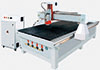
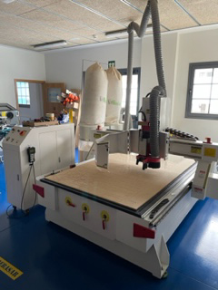
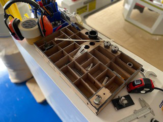
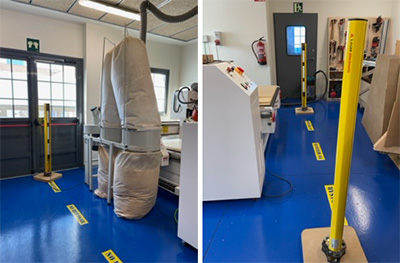
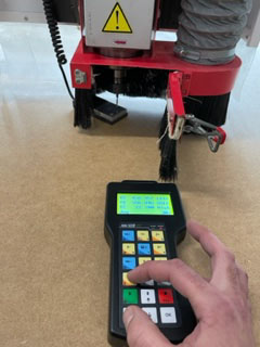
This week consists of creating a large object using a machine called a CNC milling machine. Before making the object, we need to adjust the speed, motion and other factors to make sure the machine is working properly. Once we’ve adjusted everything, we can start making the actual object. The image shows the machine we’ll use. It has a work table and a head that moves in three different directions, (X, Y, Z).
It also has a control panel with buttons and a remote control that we use to operate the machine.
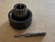
The TEC-CAM 1103 S-6.0 CNC milling machine is a machine that uses a process called machining to cut materials. This technique involves the use of a rotating tool (milling cutter). To perform the cut, the tool rotates and moves in a specific direction.
The milling machine can work with different types of materials such as methacrylate, PVC, DM, solid wood, brass, porexpan, foam and others. It is important to choose the right cutter for the material to be cut, as each type of material requires a specific type of tool.
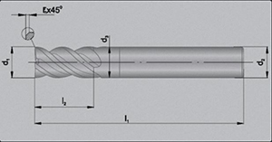
- Cut diameter d1
- Shank Diameter d3
- Cutting Depth l2
- Tool type
- Number of lips
- Type of material
- Material width
- Displacement speed
- Turning speed
In the design process, it is important to note that certain machining tools are not able to create internal corners with sharp angles of 90 degrees. Therefore, it is necessary to prepare these corners before machining if you want to assemble the part with other parts.
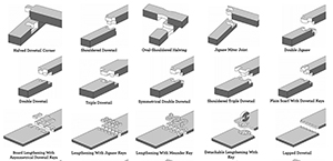
In addition, there are different types of assemblies and structures that can be used in the design, such as CNC carpentry, digital joints, live hinges and push-ups. It is essential to consider these options and select the right one to achieve the best result in the design.
There are many ways to make a pressfit without using screws, or glue. Such as the image below:
The tests carried out will be used to design the following product, which is a large piece of furniture in which several pieces have to be mounted on top of each other. The following explains how the product has been designed, prepared, manufactured and assembled.

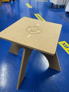
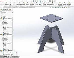
I’ve thought about making a stool, since I only have two chairs at home so I can have something else. I also plan to make a bench with include curved surfaces. Next, I show the steps I have done to make the stool.
I have created in solidwork a stool simple, practical and easy to assemble. You can also check that the parts are well assembled and there are no collisions. The different pieces are fitted with pressfit and with adequate distances and tolerances so that everything fits perfectly.
Then piece by piece I have saved it with extension . dxf to send it to VCarve and Rhino. With this program you can order the parts inside the table to be machined and facilitate the work.
Download

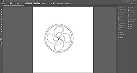
I will make a lauburu in Illustrator. This sign is one of the most representative and recognizable symbols of Basque culture. Then I’ll insert it into the base of the stool to make it an engraving.
Download
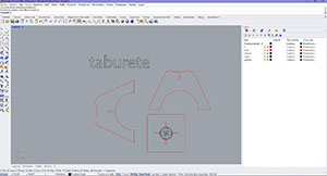
I have created a Rhino document. With this program I will be able to order the parts inside the table to be machined and facilitate the work. I also inserted the lauburu for engraving. Then I saved it with extension .dxf to send it to VCarve.
Download
1.- The first and very important thing to do is to import the library of milling cutters that we have in the FabLab.
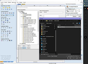
2.- After opening a dxf, in this case a stool leg
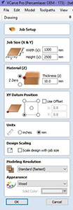
3.- Material configuration: - Dimensions (X, Y): We specify the dimensions of the Milling Machine working table. Our Milling Machine measures 1300mm wide x 2500mm high.
- Material: We specify the thickness of the material and the 0,0 point of the thickness. In this case 10mm.
- Origin position XY: We specify the point 0,0. In this case I have put it down to the left, although it is possible to put the point 0.0 where you want.
- Unit: in mm
- Scaling data: If necessary you can scale objects to material
- Model resolution: You can choose the material appearance and model resolution
4.- After filling in the data click "accept"
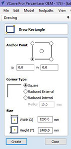
5.- Create a rectangle with the exact measurements of the material, in this case it measures 1200mm x 2400mm. Point 0,0 of the material should also be specified.
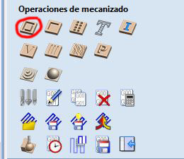
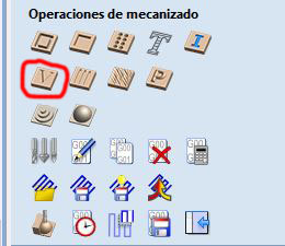
6.- Place the part inside the material.
7.- Tool paths> machining operations> and in this case as it is a total cut, ie profiling, we select the corresponding icon.
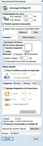
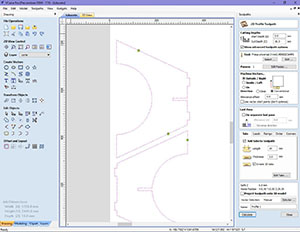
8.- 2D Profiled Strategy:
- Cutting depths: Initial depth 0.0. Final depth: It is the sum of the thickness of the material plus a little more to make sure that it cuts completely. In this case my material measures 10mm thick and in final depth I will put 10.30mm.
- Tools: We select the type of cutter in our tool list library. In this case as I am going to make total cut I will use a flat cylindrical cutter of 4mm diameter. The number of passes indicated 1, that is, the cutter will cut the 10.30mm at once.
- Machining vectors: We can indicate that the cutter goes inside our design or outside, in this case I will indicate outside and direction according.
9.- Once you have the desired parameters, click "calculate".
10.- In the "new" tab we click and we will see the trajectories and the direction of where the milling cutter will go and the beginning.
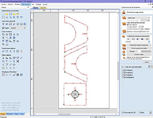
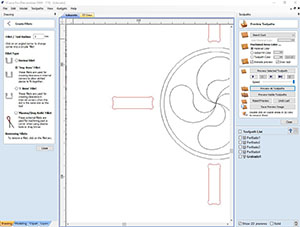
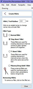
11.- It is also important to create spokes in the interior areas. Indicate the radius of the milling cutter. The cutter I will use is 4mm in diameter. It is important because otherwise the corners make them rounded and you could not mount the pieces well. With which doing this we will avoid rounded angles.
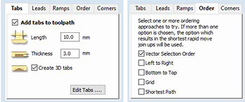
12.- Add tabs to make sure the material does not move when the cutter cuts the pieces, I will add two per piece to make sure. Indicate in this case 10mm wide and leave 3mm thick. Also select Order: Vector selection order.
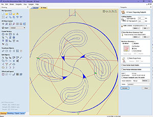
13.- To make the engraving happen two things and is that the thin and thin areas will be made with a pointed milling cutter and the more open and wide areas will use a flat milling cutter to make the engraving last less time. If I make all the engraving with the pointed cutter, it would take about 40min to finish, but if I change the milling cutter it would take 8 min. So we sent two trajectories for the engraving.
The first path with 60 degree tip cutter in the interior and thin areas of the drawing as shown in the picture. With an engraving depth of 3mm.
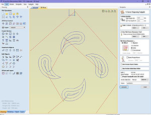
The second path should be clicked "use flat area clearence toll", to select the cutter, in this case with flat cutter, for the exterior areas of the drawing as shown in the image. With an engraving depth of 3mm.
Obviously I have to take into account that, when performing these trajectories in the milling machine, I will have to physically change the cutter and calibrate etc...
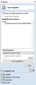
When storing the trajectories, it must be taken into account what type of processor the milling machine has, in our case is G-Code Arx in mm.
The first thing is to install the security system. Several lasers and mirrors are placed to make an area where, if a person crosses the safety line created by the laser and mirrors, the milling machine stops. It must be calibrated so that the laser collides with the mirrors and goes towards the direction of the second laser
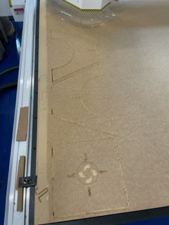
Once the trajectories are defined, we go to the milling machine, place the milling cutter and the material and send the works. These are the steps to follow.
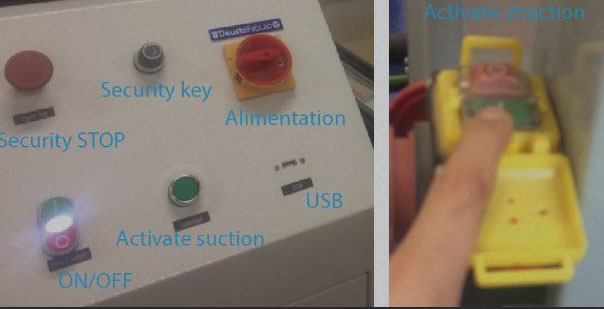
It is important to have some device to clean the work table so that our material rests perfectly on the table: a compressed air machine and/or a vacuum cleaner, for example. We turn on the power and activate the suction.
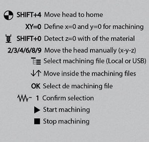
Here are the different commands:
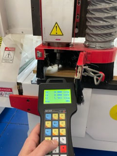
- Once the machine is turned on, SHIFT+4 must be used for the milling machine to go home.
- Then place the cutter on the head correctly, and manually with the left and right commands to define the point 0.0 and use the XY=0 button to confirm the desired point 0.0. In this case down to the left.
- To calibrate the Z axis, we move the head to the center of the table more or less and place the sensor pressing SHIFT+0. This will cause the cutter to touch the sensor and calculate the height in Z. It is important that the suction is activated!
- Enter the path menu and select the desired file in the following order:
1.- Select the file> ok
2.- We select 1 to confirm
3.- Green button: star machining
We just have to wait so we can’t get away from the machine and we have to have the remote control in case we have to stop machining. Once finished remove the desired parts, clean the machining table. At the time of assembling the parts I had an error when assembling as I had left a short distance from pressfit and had to re-manufacture one of the parts.