WEEK 6: Electronic Design
INDIVIDUAL ASSIGNMENTS
The following basic elements are needed to design a microchip board:
- Integrated circuit design (CAD) software that allows the creation of an outline and a design for the board.
- Solid knowledge in electronics, including circuit design, electrical signal management, component selection and knowledge of digital logic.
- Access to laboratory equipment such as welding tools, oscilloscopes, multimeters and power supplies.
- Design specification: Define the technical requirements of the microchip, including the function to be performed, the plate size, the number of input and output ports and the power requirements.
- Circuit design: Create an integrated circuit scheme that meets technical specifications and size and energy limitations.
- Plate design: Design the board that will house the integrated circuit, using CAD software and ensuring that it conforms to the circuit scheme and technical specifications.
- Component selection: Select the electronic components needed to build the integrated circuit and board.
Concepts to know:
- Resistor: Limits the flow of the electrons through a circuit. The resistance is measured in ohms Ω. And an important aspect that we have to look at is the tolerance: how accurate it is. Current(I) = Voltage (V)/Resistor (R)
- Capacitors: They store energy in an electric field and they can control voltage spikes (they “clean” circuits “noise”). They can be polarized and un-polarized. Capacity =Charge (Q)/Voltage (V)
- Regulator: It has a capacitor after. It establishes the voltage that you will have after it. If you have a higher voltage, 5V for example, you can regulate what it goes out, 3.3V for example.
- Micro-controller: Brain of the PCB, each pin could have different functionalities, which would be defined later with Fuses.

This week’s task is to design your own board by adding a button and LED. I am unaware of this and have had to read a lot and document myself. I have never used the corresponding programs for it either. I started by installing the Eagle, and gradually understanding and exploring it. Little by little I was able to get what was asked. It has cost me a lot, and I think that little by little I am understanding what concerns electronics, although I still have a lot to understand. The first and most important thing is to download the library to access the different components etc.
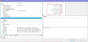
Little by little I have been adding the components that I think I need for it, it is quite intuitive. I also had to learn what the components are called and what they are used for and how they are represented in figures, to know what I have to put in the sketch.
The following components are:
- Microcontroller: Attiny44-SSU
- Button
- LedFab1206
- Capacitor
- Resistance
- Diode: current from anode to cathode
- AVRISPSMD
Once elected I was creating unions between them, it is quite intuitive and logical, although I have tried many things until in the end I have been understanding it. How I should place the components, how to call the different parts of the elements, if you need to rotate, reflect, etc. Everything has to match. It is important to place it neatly and having an idea of how it can be placed so that later on the "board" it is not so difficult to join the tracks without crossing. Have a more or less defined scheme to work more comfortably later.
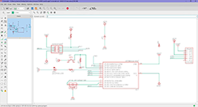
Once done, the next step is to create the joints of the components without crossing. And also very important that all the components are perfectly defined and that none is missing. When I got to this step I found that I can not join the tracks well without them crossing and I had to start again and organize it better. Besides, I needed to put up a resistance. so it’s better to start over from scratch.

The second attempt was much better. It is important to put in microcontroller in the middle and around the different components to have everything better organized and clear. With the different tools you can create paths, move, reflect, rotate etc, according to the needs you have. I have had to change the elements many times until in the end I have been able to put it in a way that the tracks do not cross. You have to take it as if you were playing with a puzzle.
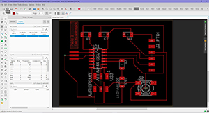

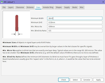
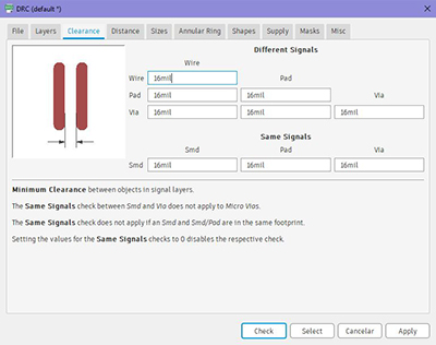
On Tuesday, one of the instructors of FabLab León told me that the roads should be wider. Then I went to the "Board" in clicking DRC you can change the parameters of the tracks, width distance between them, distances between elements etc.

I don’t know much about electronics, but I’m learning a lot. Eagle is fun and enjoyable and they fly by. I really liked everything I learned this week and I only could almost without help.
Download
GRUPAL ASSIGNMENTS
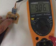
To finalize the exercise, different checks have been made with the multimeter.
It is very important to learn how to use this tool, as it can help to identify short circuits and errors in component values, which may otherwise go unnoticed.