WEEK 4: Embedded programming
INDIVIDUAL ASSIGNMENTS
The challenge this week is to schedule an Arduino, I’ve never done it and I’ve never seen one. I have no knowledge of electronics so I will have to do my best to move on.
The steps were clear thanks to the explanation of my Instructor and Neil, but still everything is unknown to me.
It seems that programming an Arduino is quite easy so let’s get to it. The steps I have to do are the following:
- Download and install Arduino software
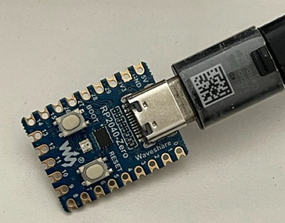
- Connect the Arduino to the computer using a USB cable. (in my case USB type C)
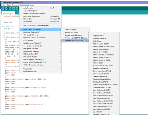
- Select the board type: In the Arduino software, select the board type you are using (for example, Arduino One) from the "Tools" menu.
- Select the serial port: Also in the "Tools" menu select the serial port to which the Arduino is connected.
- Write the code: Write the code for the program you want to load in the Arduino editor. The code is written in the C++ programming language.
- Check the code: Before loading the code in the Arduino, verify that there are no errors in the code by selecting "Verify" in the "Sketch" menu (Sketch). The verification process compiles the code to verify that it is valid.
- Load the code: Finally, load the code in the Arduino by selecting "Upload" in the "Sketch" menu (Sketch). Arduino software loads the code into the Arduino and runs it.
Once the code has been loaded into the Arduino, the device will be ready to perform the task for which it was programmed.
The first thing I have done is to know the program of Arduino. Know it and clarify certain concepts such as:
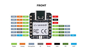
The Arduino RP2040 is a microcontroller board developed by Arduino in collaboration with Raspberry Pi. It is based on the Raspberry Pi RP2040 microcontroller, which features a dual-core ARM Cortex M0+ processor and SRAM 264KB.
MOSI, MISO and SCK are three communication signals used in the communication protocol SPI (Serial Peripheral Interface) in Arduino.
MOSI (Master Output Slave Input) is the master’s output signal and the slave’s input. The master sends data through this signal to the slave. MISO (Master Input Slave Output) is the input signal of the master and the output of the slave. The slave sends data to the master through this signal. SCK (Serial Clock) is the clock signal used to synchronize data transmission between master and slave.
In short, MOSI and MISO are the signals used to send and receive data between devices, while SCK is the clock signal that synchronizes data transmission between devices. These signals are commonly used in applications that require fast and reliable communication between devices, such as in communication between a microcontroller and a peripheral device.
Makefile is a text file that contains a set of rules that define how source files should be compiled and linked to generate an executable file. In the context of AVRDude, Makefile is used to automate the AVR microcontroller programming process with AVRDude software.
AVRDude is a command line program used to program AVR microcontrollers manufactured by Atmel. The software allows you to load firmware programs into the microcontroller’s flash memory via a serial, parallel or USB connection. AVRDude is commonly used in electronics and robotics projects to program AVR microcontrollers on Arduino cards, among others. A Makefile for AVRDude can contain a set of rules that define how the source code should be compiled and linked, how a HEX file should be generated, and how the HEX file should be loaded into the microcontroller with AVRDude. For example, a rule can define how to compile the C file and how to link the generated object file to create an executable file. Another rule can define how to convert the executable file into a HEX file and how to load the HEX file into the microcontroller using AVRDude.
By using a Makefile to program AVR microcontrollers with AVRDude, you can automate the process of compiling, pairing and loading firmware on the microcontroller, which can save time and simplify the programming process.
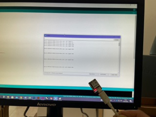
Here I show the information of the data sheets

I followed Neil’s steps to understand the basic steps and how they work.
First copy the code into a new Sketch
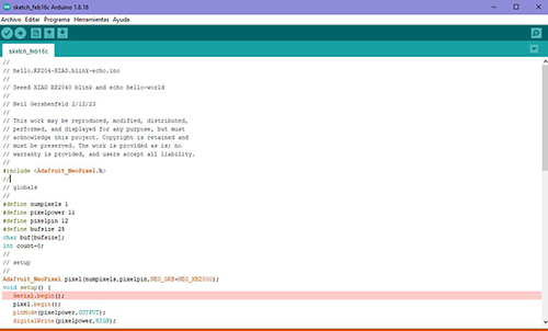
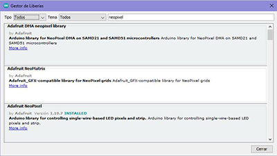
Then in the library administration correctly install Adafruit neopixel.
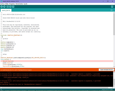
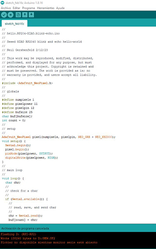
And when uploading gives error, maybe it is because the cable that connects the computer with the microchip is not correct since it has an adapter or that the cable is damaged and does not read the microchip, since when I go to "Port" does not appear. I’ll change the cable without an adapter and do the same steps again.
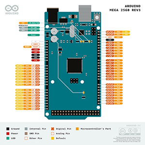
While fixing that problem, try another board, this time on an Arduino MEGA 2560. With another example different from Neil’s.
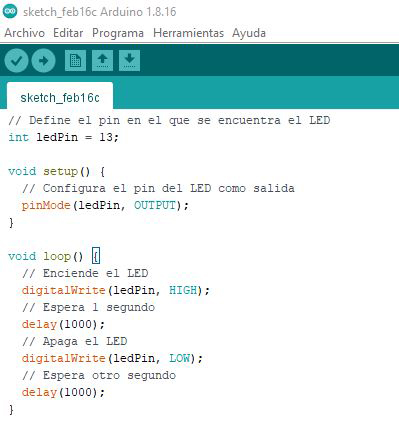
This code I have used Arduino pin 13 to connect a LED. In addition, you can adjust the timeout to make the LED flash faster or slower by changing the value of the "delay" parameter.This code is made with gpt chat, given the little knowledge I have about coding, and it is learned also with this platform. It has clarified a lot of things for me because it explains step by step what it does.
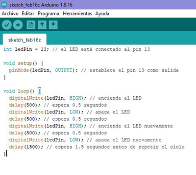
This other code example (making an LED blink twice every second in Arduino) makes use of Arduino’s digitalWrite() and delay() functions. The digitalWrite() function is used to turn the LED on or off on pin 13, and the delay() function is used to set the timeout between turning the LED on and off.
The timeout is set at 500 milliseconds (0.5 seconds) to make the LED flash twice per second. In addition, there is a standby time of 1.5 seconds (1500 milliseconds) at the end of the cycle to make the LED flicker repeat every second.
The problem I had earlier was that the cable does not serve for data transfer, just to read or charge the betería of my headphones, since it has only one ground cable (GND) and the other (VCC).
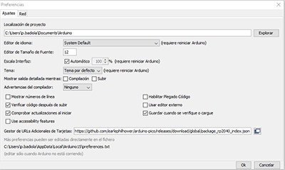
I also had to put this code in additional card manager preferences. And install it in the RP2040 library manager.
Once this is done copy the code into Arduino and verify it.
I have changed some code values to modify its behavior. Here are some possible modifications:
- Change the number of pixels of the NeoPixel LED
- Change delay duration between NeoPixel LED color changes:
#define numpixels 1 // cambiar a 2 para usar dos píxeles
delay(100); // cambiar a un valor diferente, por ejemplo 500 para un retardo de 0.5 segundos
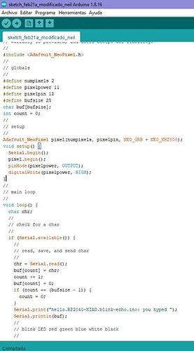
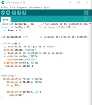
This code is a simple example of how to control an LED and a button on an RP2040 board using Arduino. The RP2040 board is a low cost and high performance microcontroller developed by Raspberry Pi. The code defines three variables: buttonPin, ledPin, and Power. The buttonPin is used to read the status of the button, the ledPin is used to turn the LED on and off, and Power is used to turn the power on.
In the setup() function, the ledPin and buttonPin pins are configured as output and input, respectively, using the pinMode() function. In addition, the Power pin is configured as output and set to HIGH to provide power to the board. Finally, serial communication starts at a rate of 115200 baud using the Serial.begin() function.
In the loop() function, the "Hello, World" message is printed via serial communication using the Serial.println() function.
The LED is then switched on using the digitalWrite() function and 300 milliseconds are expected using the delay() function. Then the LED is turned off and another 300 milliseconds is expected. The signal generated by the LED will be a square wave with a period of approximately 600 milliseconds (300 milliseconds on and 300 milliseconds off).
GROUP ASSIGNMENTS
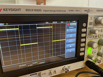
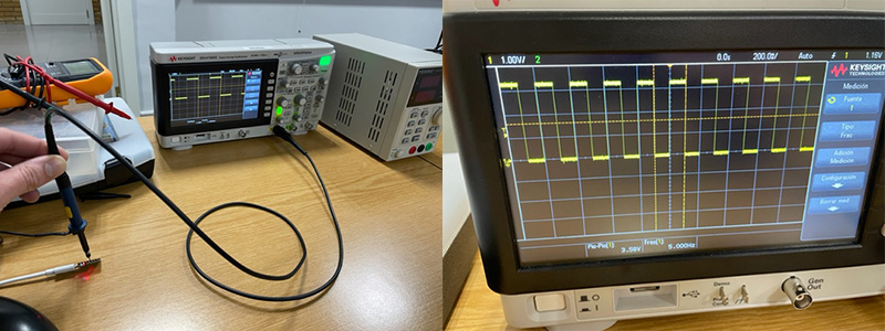
Below are several examples with input and output so you can then view it on an oscilloscope and compare performance and development workflows by testing against the code above. "Blink"
As for connecting it to an oscilloscope, a signal is generated that can be displayed on the oscilloscope. The signal generated by the LED will be a square wave with a period of approximately 600 milliseconds (300 milliseconds on and 300 milliseconds off). If you connect the LED through a current limiting resistance and measure the signal with the oscilloscope, you can see this waveform.
If the value in delay() is changed, the resistance will also be changed. Here are different examples.