WEEK 3: Computer controlled cutting
GROUP ASSIGNMENTS
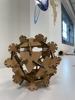
This week is dedicated to laser cutting and vinyl cutting. These are technologies that are on the FabLab and I love using them. The task was to characterize the laser cutter and manufacture test tests on "focus", "power", "speed", "rate", "kerf" and joint clearance. Also with the laser cutter, cut design a parametric kit with press-fit.. One of the conditions was that the snap-fit construction kit would be assembled in several ways.

Specifications of the machine:
- Working area is 813 x 508 mm
- Laser tube: 75 W CO2
- Resolution: up to 1,200 dpi
- Fixing System: Gravity System
- Weight: 227 kg
- Vector: dwg, xf, eps, ai, pdf
- Raster: bmp, jpg, gif.
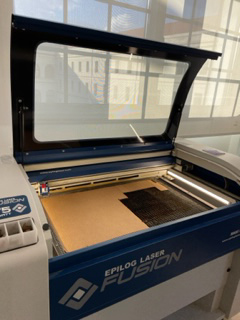
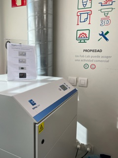
We turn on the machine and open the lid. We place the material, in this case cardboard, on the bed of the laser cutter. Our 0.0 point is at the top left. We have some small tweezers to better hold the material if necessary.

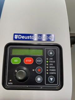
Then on the control screen "focus mode" is selected. This will allow us to raise and lower the bed with the help of the joystick.
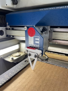
This arrow-shaped piece will help us focus the laser cutter.
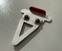
We place the arrow between the two screws and with the joystick we make the tip of the arrow in contact with the material. Once properly focused it is important to remove it. We know it’s focused when the arrow grazes the material.
Once everything is correct and the material perfectly placed we close the lid.
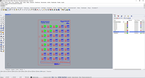
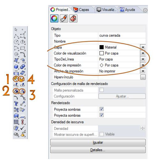
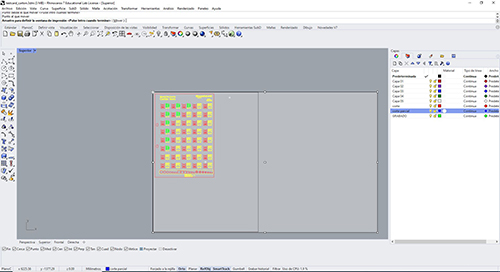
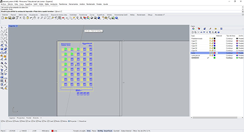
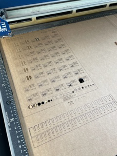
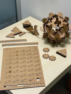
I started to create a template that reflects the values about "power", "speed" and "frequency". Defining correctly with layers of engraving, partial cutting and total cutting. Before that, I had to test to see how far the result of each 3mm Carton test was optimal. You also have to take into account the properties of the design that all this by layer and when making a design, you have to check that all the lines that compose it are united. It can be done using the command line at the top or with the tools in the toolbar. Once everything is right I set out to send the laser machine the "works"
RASTER
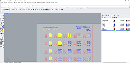
We select the engraving layer> "CNTR+P"
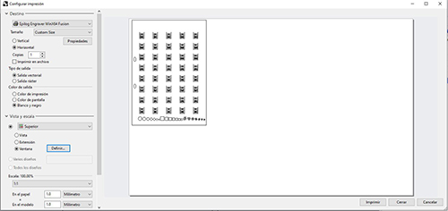
Tab view and scale> define> we match the 0.0 point of our design with the 0.0 point of the laser machine. To do this we must click the word move on the command line. Then enter.
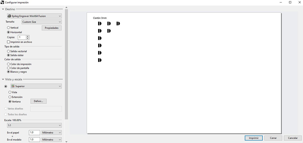
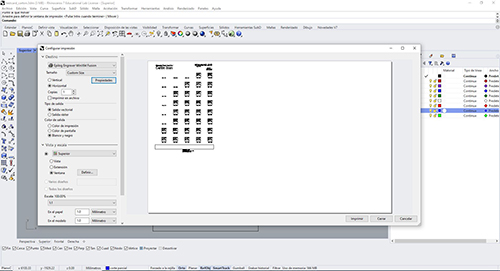
Then select layer (in this case the engraving)> cntr+P and we see the printing settings).
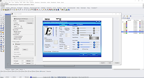
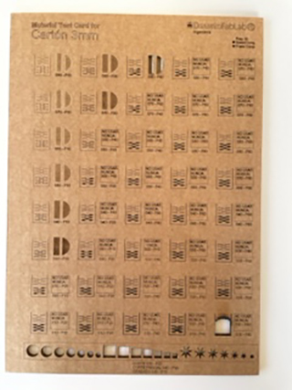
Target tab> properties A menu appears in which you have to click raster and illuminates the properties of this. We select the power and speed we want and best suit us with the sample book we have available (image above).
"Engrade direction": Click the arrow and you have to be looking up, so that the smoke goes up and the engraving result is optimal and clean.
"Image dithering: the "quality" of the engraving. If you want to perform something very accurately it is recommended use "Jarvis" mode, if not, the "Standard" also works well.
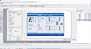
Once the fields are filled in, click OK>PRINT and the file is automatically sent to the laser cutter.
PARTIAL CUT=VECTOR
Tab view and scale> define> we match the 0.0 point of our design with the 0.0 point of the laser machine. To do this we must click the word move on the command line. Then enter.
Target tab>properties> A menu appears in which you have to click vector and illuminates the properties of this.
We select power and speed that we want and best suit us with the sample book that we have available (image above). We must also set the frequency to 80. (in methacrylate the frequency is 100 and in wood 85).
Once the fields are filled in, click OK>PRINT and the file is automatically sent to the laser cutter.

TOTAL CUT=VECTOR
We select the Total Cut layer> "CNTR+P"
Tab view and scale> define> we match the point 0.0. To do this we need to click the word move on the command line. Then enter.
Go to the Target Tab>properties> A menu appears in which you have to click vector and illuminates the properties of this.
We select the power and speed we want and best suit us with the sample book we have available (image above). We must also set the frequency to 80. (in methacrylate the frequency is 100 and in wood 85).
Once the fields are filled in, click OK>PRINT and the file is automatically sent to the laser cutter.
Once the Jobs sent to the machine, before starting the printing we have to take into account:
- Turn on compressed air
- Turn on the extraction
- Once lit we can start making "GO"
Once the work is finished we turn off the extraction and compressed air and we can remove the material from the laser cutter.
Download

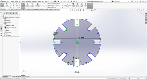
Once we know which values we should select, I set out to design a "parametric comb" to know which optimal measurements are best for press-fit.
I’ve used solidworks to do it. It’s important that we define the parametric equation well in dimensions. Selecting the dimensions and putting the values that best suits us.
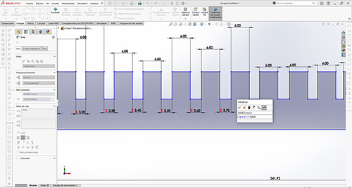
In the Equations tool> right click> manage equations, and we put the measurements and create values.
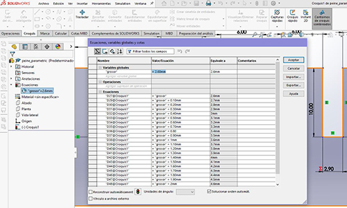
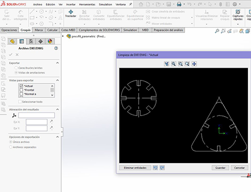
Once the file is created, we must "save as" . dxf, in order to open it in Rhino and send it to the laser machine. This is the program used to communicate with the machine.
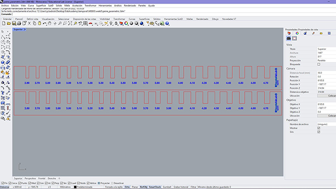
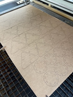
Taking into account the above mentioned in terms of the preparation of the machine and shipment of designs we are preparing to manufacture the "parametric comb".
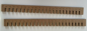
Download
INDIVIDUAL ASSIGNMENTS
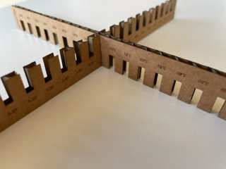
The next day I started designing in solidworks, a sketch and I was inspired by previous projects at Fab Academy. A parametric design, but at the same time constructive. The design must have two components, each with at least one variable for the total height.
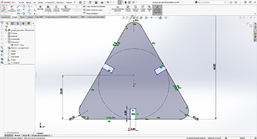
Then we save it as dxf so we can open it in Rhino and prepare it properly with well-joined lines and defined layer.
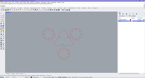
Taking into account the above mentioned regarding the preparation of the machine and shipment of designs we are preparing to manufacture the "parametric comb". I’ll prepare a cardboard plate to duplicate the pieces and have them cut.
Download
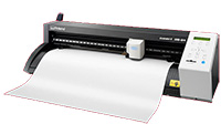
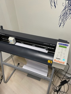
Specifications of the machine:
- Cutting area: 584 x 25000 mm
- Material thickness: up to 0.5 mm
- Mechanical resolution: 0.0125 mm/pitch
- Weight: 16 Kg
- Allowed formats: .DWG, .DXF, .EPS, .AI, .PDF
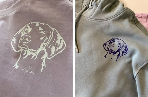
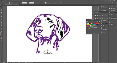
On Monday I started to design something for the vinyl cutter. I decided to draw a picture of my pet. I have a Weimar Braco and I would like to have a garment of it and have a memory forever.
There are many types of vinyl, in the Fablab we have the following:
- Adhesive vinyl (labeling) to stick on surfaces
- Thermo-adhesive vinyl: for textile garments and also elastic vinyl
- Copper vinyl for plates
The roland machine has a blade that if you want to cut small designs you should use a 60 degree blade, and if they are big designs as is my case I will use a 45 degree blade.
First we stage the machine and we put in thermo-adhesive wine in the base.
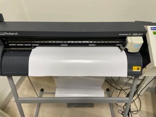
It is important and a number of things must be taken into account:
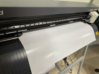
- The rollers have to be on the white check marks and at the same time as far from each other.
- The vinyl has to cover the sensor
- The vinyl has to be parallel to the guide lines of the machine.
- The "shiny" part of the vinyl down
- Push the lever upwards so that the rollers step on the material.
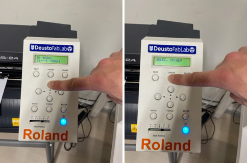
Once the adhesive vinyl is placed correctly, we go to the monitor and select the option of "roll"> enter since in the machine I have put a roll.
There are also more options to choose, for example: Part or edge that serves for pieces of material and that the blade will measure the width and length.
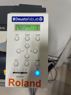
Once we select "roll" we click "enter" immediately the machine measures the width of the roll. Once measured, the measurements of the material placed will appear on the screen. If we place part the machine measures width and length.
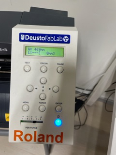
It is important to press the arrow upwards to collect the material and then press "origin" so that the blade begins at the point we indicate and thus not waste material.
Once these steps are finished we have the machine ready to print, but before starting it you must send the design to the machine. Here are the steps to do this.

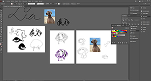
Select a photo that I liked the most about my pet and with Bézier’s pen in illustrator I started drawing. In one layer the photo by lowering the opacity a little to see better and so that the photo does not move block it and in another layer my drawing.
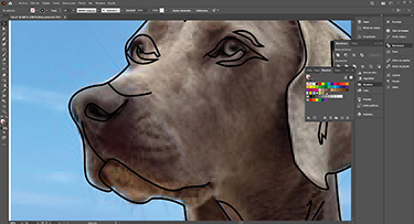
Gradually I started to shape it by starting a general idea and then modifying points, nodes, and handles with the "direct selection arrow". The drawing is not exactly the same, but I think the essence looks like my pet.
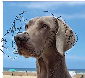
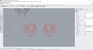
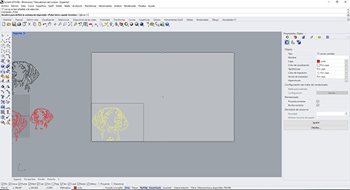
Once finished the drawing, I opened the rhino to send our design to the vinyl cutter
It is important to reflect our design because when turning the vinyl to put it on the garment would be right.
Then select the design and press "CNTR +P".
Destination tab > Get from machine> to adapt the vinyl size to our design size and know that the design will fit perfectly.
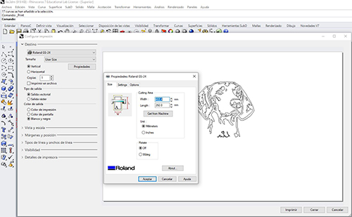
Tab view and scale> define> we match the point 0,0 of the vinyl with the point 0.0 of the design. To do this we must click the word move on the command line. Then enter.
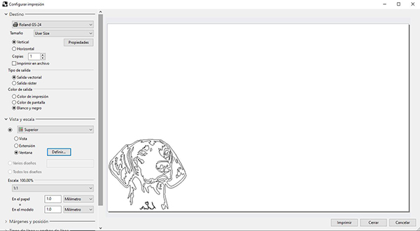
Once defined all parameters as we have prepared the machine and correctly placed the material click print and automatically the vinyl cutter will be launched.
Vinyl moves in "Y" axis helped by the roller, and in "X" axis moves the blade.
After the machine finishes the work we remove the material and with the help of the hook we remove the parts of the design that we do not want.
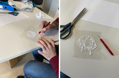
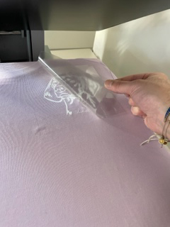
Then put on vinyl on the garment. It is important the placement, the vinyl must be in contact with the fabric and the transfer in contact with the iron. That’s why it’s also important to reflect the design.
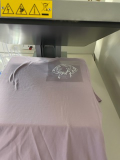
When the iron reaches about 150 degrees we can lower the lid and wait about 15 seconds to lift the lid
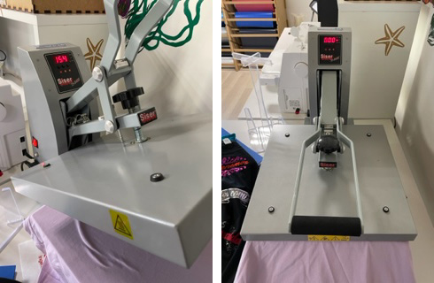
After hot, the transfer is carefully removed
This is my end result, I have done it in several garments with different colors. I am very happy with the result and I love the design I have made.