WEEK 13: Networking & Comunications
In this week, the data collected by the board designed in the Output Device exercise will be displayed on an interface. For this we will use the Arduino software.
This Arduino code controls a servo motor using serial communication. It allows to receive commands from an external device and move the servo motor to different positions based on the received commands. Below, I will describe each part of the code:
#include
Servo servoMotor;: A variable called "servoMotor" of type "Servo" is declared. This variable will be used to control the servo motor.
int incomingByte = 0;: A variable called "incomingByte" of type "integer" is declared to store the data received by the serial communication.
Serial.begin(9600);: Starts the serial communication at 9600 baud rate. This allows communication between Arduino and the external device connected through the serial port.
servoMotor.attach(D3);: Configures the Arduino pin D3 to control the servo motor. Make sure that the servo motor is physically connected to this pin.
14-30. The code inside the loop() function is executed continuously:
if (Serial.available() > 0): Check if data is available in the serial communication input buffer.
incomingByte = Serial.read();: Reads the incoming data byte from the serial communication and stores it in the variable "incomingByte".
The following lines use the "if" control structure to check the value of "incomingByte" and execute corresponding actions according to the command received:
If command 'a' is received, the servo motor moves to position 0 degrees (far left). If command 'b' is received, the servo motor moves to position 90 degrees (center position). If command 'c' is received, the servo motor moves to position 180 degrees (extreme right). Serial.print("I received: ");: Prints a message on the serial monitor indicating that data has been received.
Serial.println(incomingByte, DEC);: Prints the value of "incomingByte" on the serial monitor in decimal format.
In summary, this code allows you to control the servo motor through commands sent by serial communication. Upon receiving a specific command ('a', 'b' or 'c'), the servo motor moves to the corresponding position.

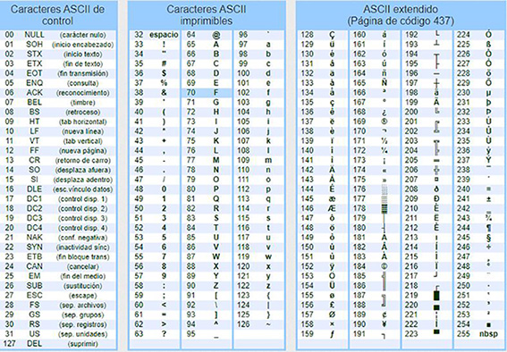
I have used the ASCII code to carry out the exercise. The ASCII code (American Standard Code for Information Interchange) is a coding system that assigns a unique numeric value to different characters used in electronic communication.
The I2C is designed as a master-slave bus. Data transfer is always initialized by a master; the slave reacts. It is possible to have multiple masters via a multi-master mode, in which two masters can communicate with each other so that one of them works as a slave. I2C is commonly used for communication between devices that are on the same circuit board.
I changed serial to serial1 everywhere. The data is taken from the bluetooth module instead of the one sent by the serial console.