4. Embedded Programming
|
This week I spent a lot of time with my favorite chip: the ESP32. More specifically, the ESP32s2, a derivative of the ESP32 system-on-chip (SoC) device. Watch this video by MAKERDEMY for more info. The ESP32s2 features a single-core Xtensa LX7 processor instead of the original dual-core Xtensa LX6. This architectural change results in improved energy efficiency by eliminating the need for the additional processor core. The chip still contains an ultra-low-power (ULP) RISC-V-based coprocessor can be used for small side tasks. Using two cores to multitask results in improved time efficiency, but the consistent 240 MHz clock speed of the single-core processor should be sufficient for most tasks. Should I need more processing power, I will just divide it up two subsystem circuits communicating between two different ESP32s2 chips. |
||||||
End Result
Let's waste no time and go right into the good stuff! This week I created an esp32s2 dev board using a through hole protoyping pcb.

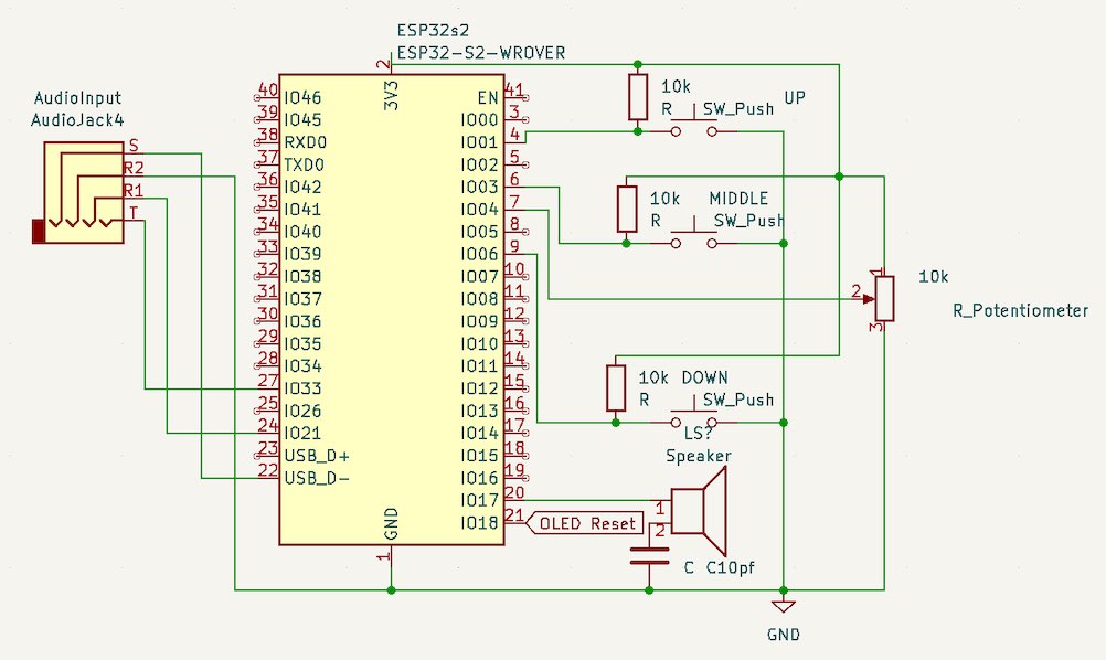
I'm going to preface with this: This is an on-the-fly circuit, meaning there were no plans. I just went through my parts, thought something was neat and added it! I have provided the schematic of it down below. Just pretend the terrible soldering on the red AUX port isn't there. This board is what I used to play around with the capabilities of the ESP32s2 and to practice my rusty C++ skills. The scope of this mini project was to learn how to create simple scripts that run on the ESP, using inputs of buttons and a potentiometer, as well as an OLED and speaker as outputs.
|
|
Project Goals:
- Research and learn more about the ESP32s2 and its capabilities.
- Brush up on my C++ programming skills.
- Set up a development environment for programming the ESP32s2, using Visual Studio Code with PlatformIO.
- Write simple scripts to read inputs from buttons and a potentiometer, and display output on the OLED display.
- Experiment with audio capabilities on the ESP32s2, such as playing tones or analog audio input.
- Research and experiment with wireless communication between two ESP32s, such as through Wi-Fi or Bluetooth.
Research:
Follow this link to see our group work for this week. There I do a breakdown of different aspects and features of the ESP32s2 I found in the datasheet and technical reference manual (linked down below). It also includes the results of a read/write speed test using the arduino library on the ESP32s2.
I've always loved a good book. Especially one as nerdy and interesting as the datasheets for the ESP32s2. No sarcasm here! To accomplish my final project, The Song Sonic , I would need to get well acquainted with how this processor works. Especially since this project is audio based, and timing is key. Later, I will show you why. But, for now I wanted to get the basics done first.
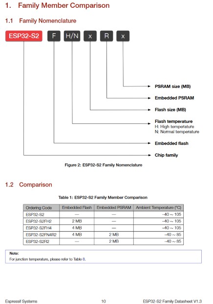
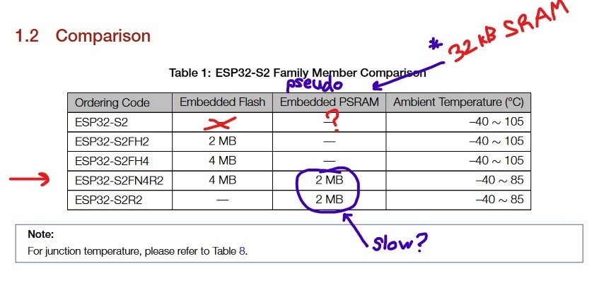
The ESP32s2 comes in 5 different packages. The one I programmed with in this project is the first one: the ESP32s2 without any extra stuff at the end.
These varying packages come with a different combination of embedded flash and embedded PSRAM (Pseudo SRAM).
The chip I used, didn't come with either, since it's the most basic package.
For my project though, this raised a couple questions as to which package would be most suitable for The Song Sonic.
Such as:
I embedded links on some of the questions where I found the answers. Spoiler alert: I went with ordering the S2FN4R2 since PSRAM, while slower than SRAM, can still useful as extra RAM. Especially where speed access is not as important, such as loading an asset for the GUI. Flash could be useful as permanent storage to save states/user settings. Since these features can't hurt to have, and the ~10 cent difference between that and the base, which doesn't seem like that much of an upcharge to be concerned about, I decided on the S2FN4R2 to also get the benefit of lower temperatures. 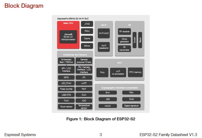
|
|
|
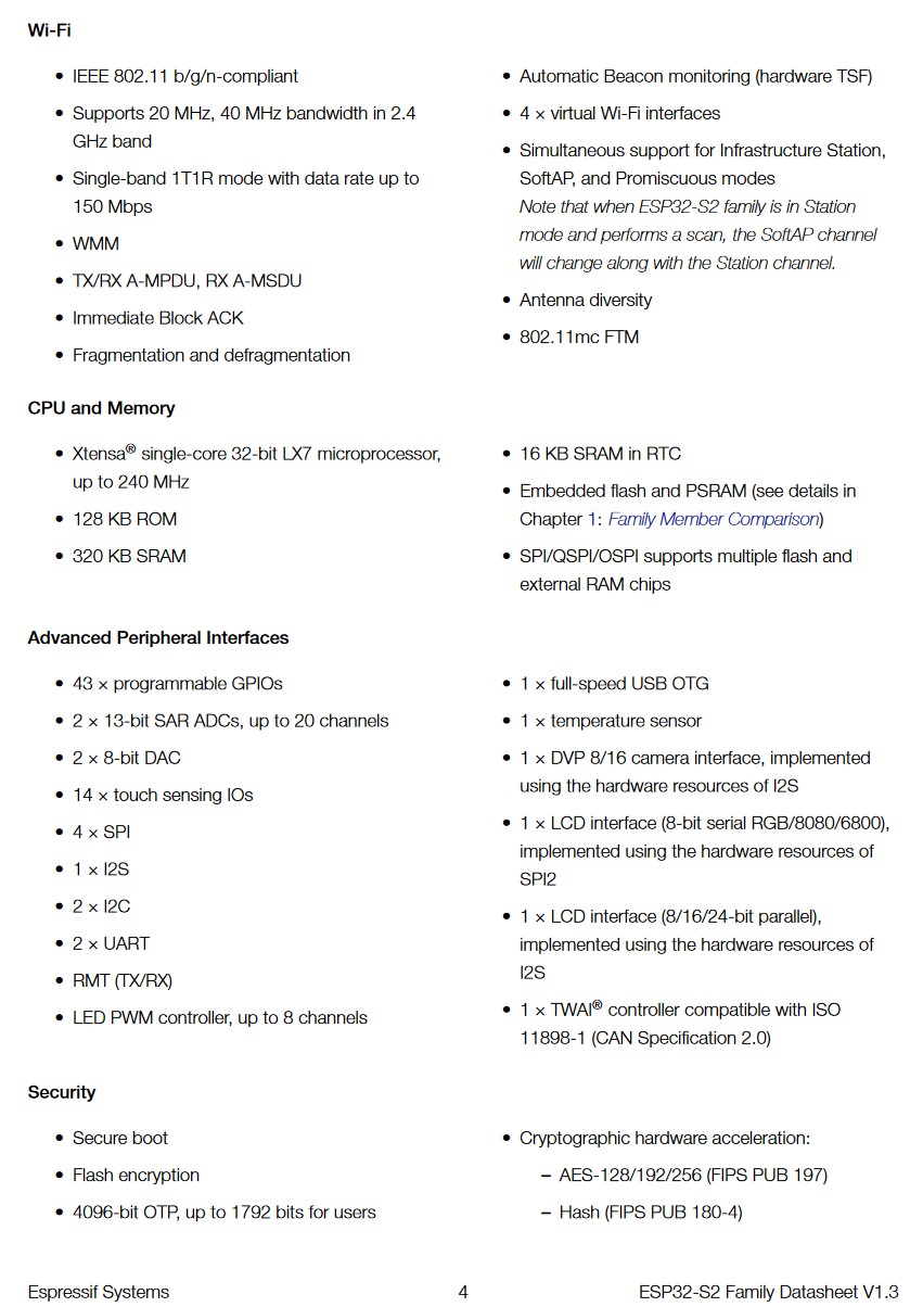
Looking at the features of the ESP32s2, there are a few things that are important to note for The Song Sonic. I am interested in transmitting high quality (at least 16 bit) signals via wireless communication between ESPs. The meager 13 bit ADC and 8 bit DAC do not meet this requirement. So, external ADCs and DACs will need to be used. I have a 24-bit ADC and a 24-bit DAC in my collection of parts, and I plan to utilize them to provide some studio-ready audio. Another important feature to note is the theoretical transfer rate using wireless communication. According to the data sheet, the ESP32s2 can provide up to 150 Mbps. So to figure out if that's good enough, I will need to do some calculations based on the sampling rate, packet size and latency. You can find that on my final project page. One final thing to note is the basically required I2S protocol. This protocol is like I2C for audio. It supports direct writing to registers, and uses a rtc that "bypasses" or is not impeded by the cpu. This is important because if I were to only utilize the serial main program to handle bit communication, I would face a lot of stuttering, latency and generally degrades audio. This is because when using serial computing, each instruction must wait for the previous to complete before it can start. So, passing parts of audio from controller to controller, all while trying to do a million other things in between, would be basically impossible if I wanted HiFi audio. |
|
Initial Code
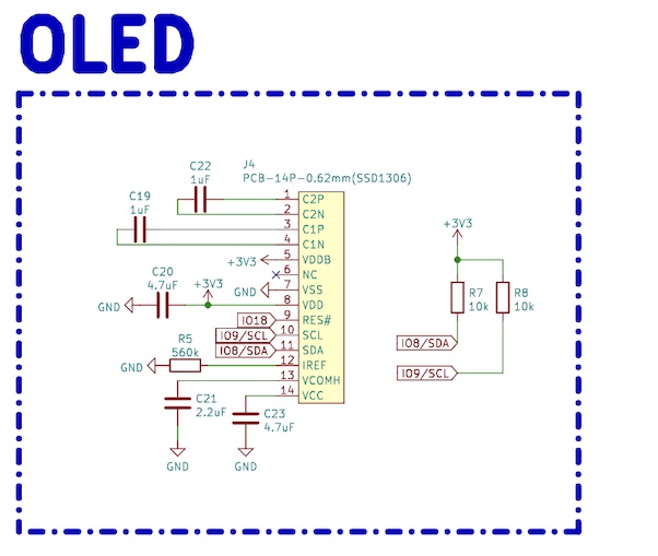
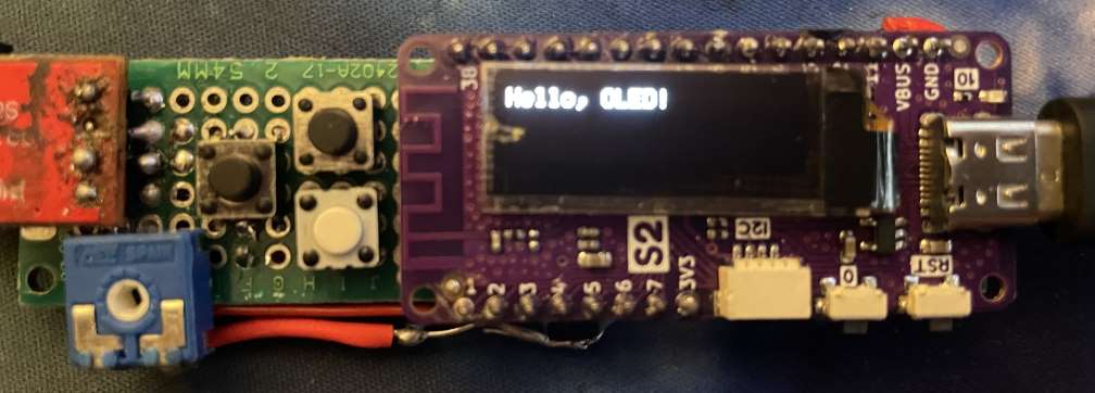
First, I wanted to get a simple script to get the OLED going. To do this I googled the project board I used. This particular version is the Lolin S2 Pico with OLED. I found this tutorial by Joonas Pihlajamaa that includes a library to control the OLED. This makes using the display convenient, without worrying about how to generate pictures or text. So, I slapped in the Adafruit_SSD1306 and Adafruit_GFX libraries into the Arduino IDE, and uploaded it to the s2 pico.
Great success!
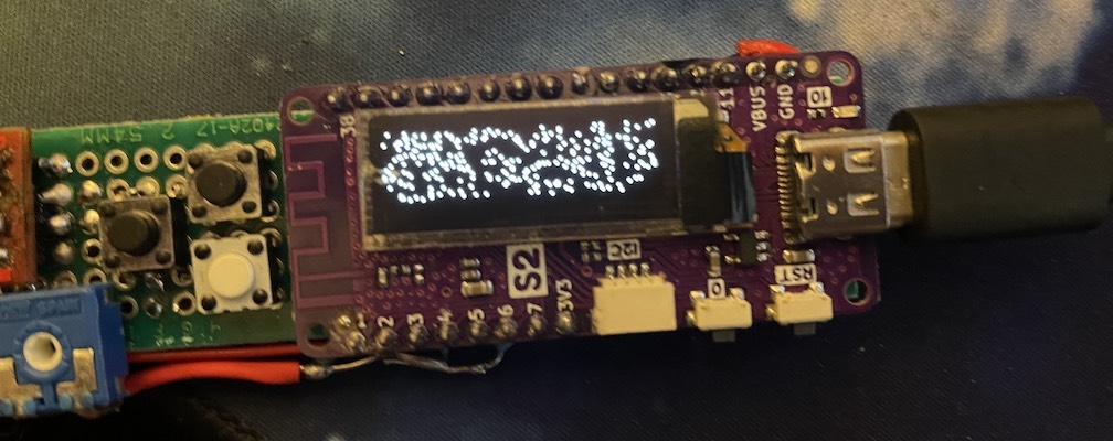
As you can see, instead of getting the "Hello, Oled!" text, I just got a random mixture of pixels. I looked around in the code, didn't find anything weird, and tried reuploading. No dice. The reset pin then caught my eye. Perhaps the screen is failing to reset properly?
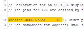
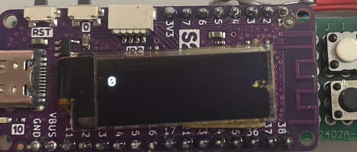
| After consulting the S2 pico schematic, I found my culprit. As I suspected, the oled_reset being set to -1 was causing this issue. I switched it to pin 18 to match the schematic. |
|
Actual Success!
Packing Up and Moving to Visual Studio Code
|
So you have to admit, the Arduino IDE is super lackluster and bare-bones. It gets the job done, but it lacks all the fancy integrated features that Visual Studio Code has such as code predictions, a variety of extensions and the flexibility to use any language. To set up my new project, I downloaded the PlatformIO extension for VSC. You can find it by looking it up in the extensions tab. This pretty much sets up your project for you with all the required files for the language you are planning to use, as well as specifics for the chosen microcontoller.
PlatformIO contains the option to easily search and download libraries, not naturally native to the arduino environment, without the use of github links.
It also comes with a settings file which when imported into VSC on a different computer, will automatically install all your needed extensions, your configured options and whatever else is needed to allow you to keep working on your project elsewhere.
After setting it up, all I have to do is plug in my ESP, then build and upload my code to it.
|

|
Programming Buttons and Potentiometer
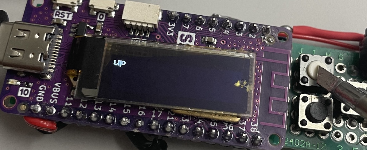
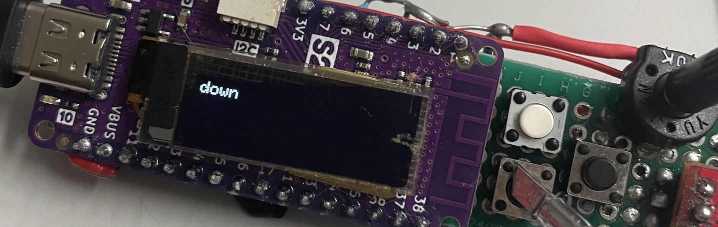
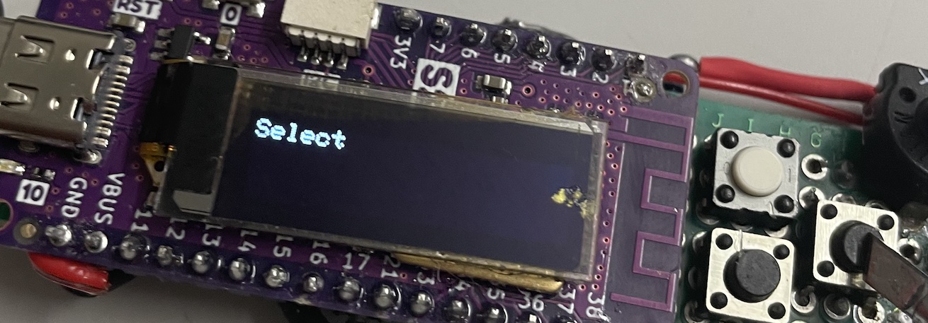
My next task was using the inputs to interact with the board. I connected 3 buttons, and one 10k ohm potentiometer. Since this is basically supposed to be a glorified waveform generator, I designated volume control to the potentiometer. The 3 buttons can be used to switch between output signals. The middle will change the mode, and the up and down buttons will eventually let me increase and decrease the frequency of the wave.
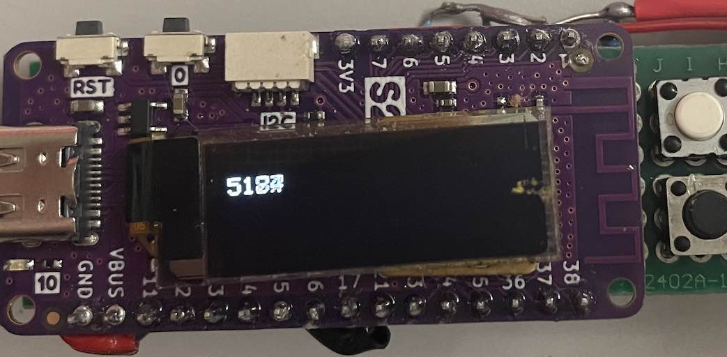
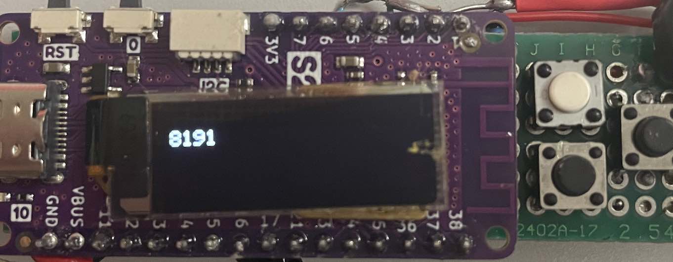
Each button is accompanied with a pull-up resistor connected between Vcc and and the pin. The potentiometer has one side connected to ground, and the other to Vcc. The middle pin is connected to the A6 pin of the microcontroller. It is important to wire it this way, without Vcc or ground connected to the middle pin. Doing so would cause a short from Vcc to ground, when the potentiometer is set in favor of a lower resistance between them. Instead, we are basically using the potentiometer as a voltage divider connected to the analog pin, which the ESP can read in as an analog measurement. The measurements picked up by the ESP itself range from 0 to 8191 aka the max value of 13 bits. That makes sense since the ADC is rated for 13 bits according to the data sheet. I was able to test this by writing the reading from the ADC onto the OLED. Here is the code I used to do so:
Dependencies: esp32s2_oled.cpp esp32s2_oled.h
      #include <esp32s2_oled.h>
      #include <Arduino.h>
      #define ADC_pin A6
      void setup(){
        pinMode(ADC_pin, INPUT);
        init_oled();
      }
      void loop(){
        int reading = analogRead(ADC_pin);
        write_to_oled_str(std::to_string(reading));
      }
|
|
As you can see, I am able to produce multiple readings using the voltage difference on the middle pin of the potentiometer. I further refined my code to use buttons with debounce, and separated each section of code into separate files.
Source Code: Multiple Files
      #include <esp32s2_oled.h>
      #include <inputHandler.h>
      #include <outputHandler.h>
      #include <defines.h>
      #include <Arduino.h>


      void setup() {
          init_oled();
          initControls();
          initOutputs();
      }

      void loop() {
        checkDebounce();
        checkControlInputs();
      }
|
|
Generating Sound Output
This part uses the same code as above, with the added line "speakerOut(getVolume());" at the bottom of loop().
I wanted to have the option to be able to analyze the sound using a small speaker attached to the device. This way, I can make sure that I have multiple ways to listen/observe the waveforms generated, without relying on external components such as plug-in speakers. I have one side of the speaker wired to the DAC pin on the ESP32s2. The other side of the speaker is wired to ground. Ideally, it would be better to connect the DAC pin to the input of an op amp, and the speaker to the output to amplify the signal - as well as isolate it from the pin.
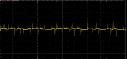
| I hooked up my oscilloscope to the DAC pin/speaker + terminal, as well as to the ground. The resulting waveform that the DAC produces was supposed to be a sine wave, but it looks pretty choppy. I am guessing there could be multiple causations such as the DAC not able to keep up with a non-interrupt based waveform. It could also be the arduino library slowing it down, and I need to use bare-metal to get proper output to the pin. Another reason could be that the DAC isn't meant to drive a speaker, ableit a small one repurposed from an old phone, and the waveform is breaking down due the load. The DAC should be giving a range between 0 and 3.3v, but on here the waveform ranges from 0 to 500mV. This suggests the breakdown theory, but it could be a combination of many things. Whatever the case, I will be addressing this problem in the future when I start using the I2S protocol in conjunction with an amplifier. |
|
Another reason to switch to the I2S protocol, is that having the sound outputs be in series with the main loop can cause lots of issues. Since the timing would be reliant on the completion of other sections of code before addressing the sound portion, adding more complex code in between would slow down the signal, resulting in lower frequencies. Not only this, but it would also be unpredictable since the amount of time instructions take could change based on many factors, such as adding or removing lines, or if the cache decided to be unlucky and miss a lot. Here is an example of how adding "expensive" operations can drastically impact the sound produced.
       #include <esp32s2_oled.h>
       #include <inputHandler.h>
       #include <outputHandler.h>
       #include <defines.h>
       #include <Arduino.h>


       void setup() {
           init_oled();
           initControls();
           initOutputs();
       }

       void loop() {
         checkDebounce();
         checkControlInputs();
         speakerOut(getVolume());
       }
|
|
|
|
|
        #include <esp32s2_oled.h>
        #include <inputHandler.h>
        #include <outputHandler.h>
        #include <defines.h>
        #include <Arduino.h>


        void setup() {
            init_oled();
            initControls();
            initOutputs();
        }

        void loop() {
          checkDebounce();
          checkControlInputs();
          speakerOut(getVolume());
          write_to_oled_str("this is expensive");
        }
|
|
The second clip is what it sounds like when you have a lot of steps happening between each update to the DAC. Which you can see why it's problematic, because it goes from a relatively audible sound to a bearily distingusihable stutter. My next step is working on getting better output from the DAC, but I plan on using a 24-bit DAC in the future. I will probably wait to get that working, instead of wasting time on the 12-bit DAC this ESP32s2 has built-in.