7. Computer-Controlled Machining
	assignment
   group assignment
      do your lab's safety training
      test runout, alignment, fixturing, speeds, feeds, materials, and toolpaths for your machine
   individual assignment
      make (design+mill+assemble) something big (~meter-scale)
      extra credit: don't use fasteners or glue
      extra credit: include curved surfaces
Individual assignment
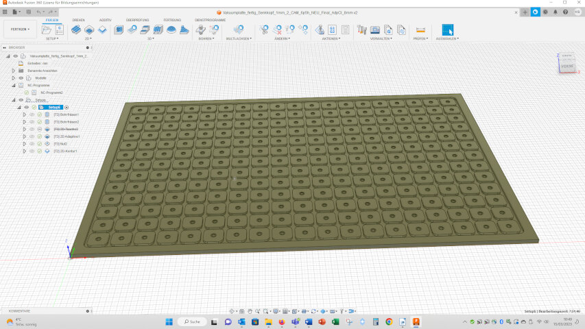
This week I planned to fabricate a vacuum table for the CNC milling cutter we want to build in the machine week. The vacuum table shall be 100x70 cm in size. I constructed it in Fusion:
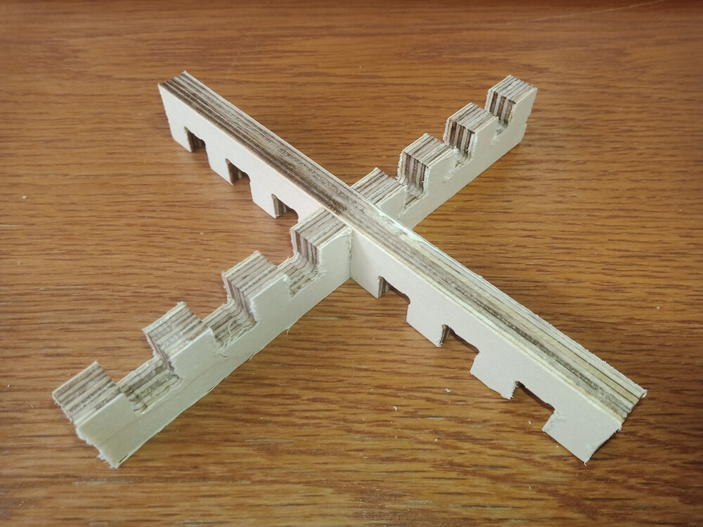
Through a hole (not shown) in one of the crossing points of the notches vacuum will be applied from below. In the notches a foam rubber band can be inserted suiting the geometry of the workpiece which shall be processed.
For the milling process I first planed to mill the 6 mm notches with a 6 mm mill, but Fusion did not allowed this. So I selected a 4 mm mill. The paths and simulation looks ok, so I loaded the milling job to the milling cutter, but the milling cutter software estimated a milling time of 6.5 hours (the estimated milling time of Fusion is way too short!). So I tried to speed up the milling process. Therefor, I used the function “Adaptive Clearing” for the crossing points of the notches and added “notches” for the linear parts of notches. In this way the notches could be cut with a 6 mm mill.

crossing points cut with “Adaptive Clearing”.
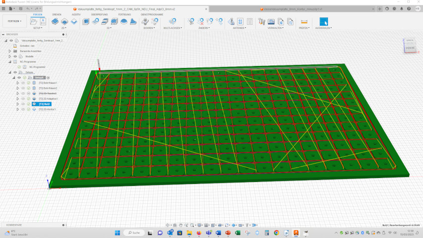
linear parts of the notches cut with the “notches” function.
In Fusion you can not use a 3D geometry to set the “notches” function, but you have to create special notches in the design file. Again the paths and the simulation looked good, but the estimated milling time was over 15 hours!!!
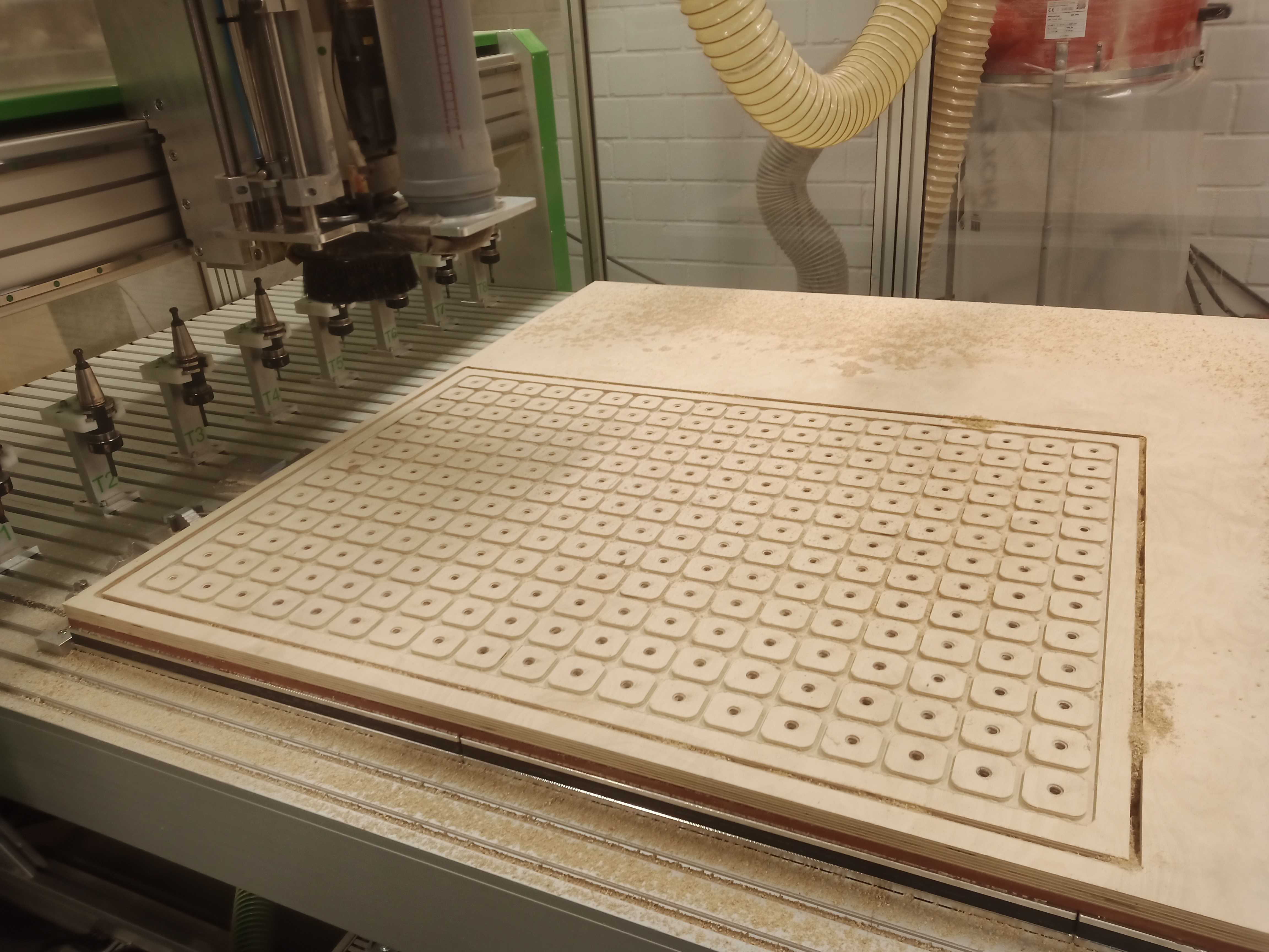
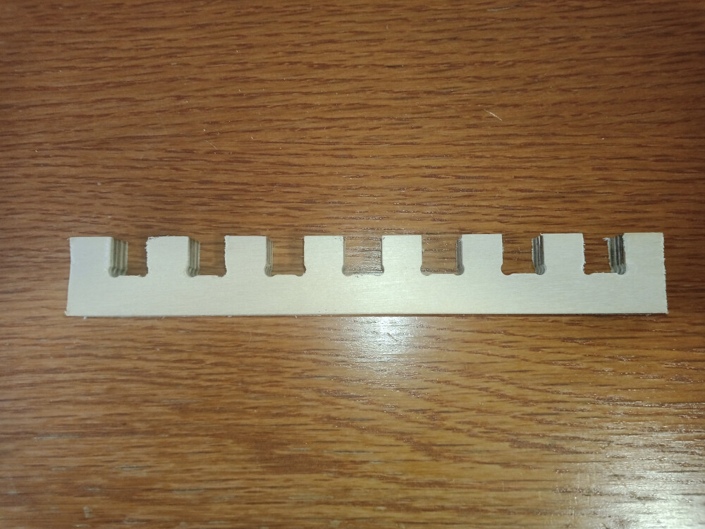
So I first designed a small version of the vacuum plate:
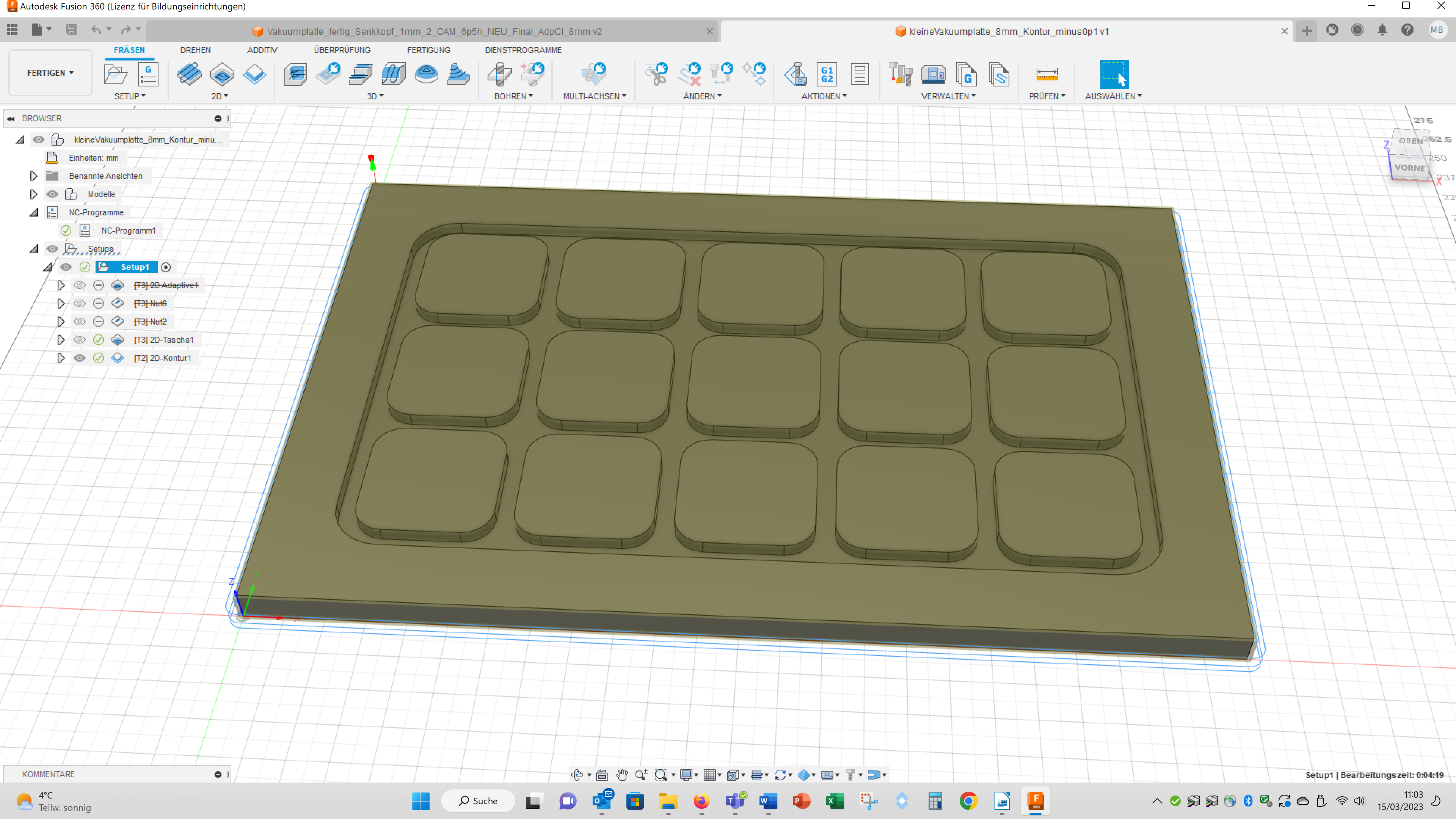
Here I only used the notch function. The estimated milling time was 49 min so I give it a try. The milling performed good, but the real milling time was about twice as long as estimated. Besides I did not find a way to select all notches altogether to compile the milling paths, but all small straight lines and all corners had to be selected manually. For the small vacuum plate this was ok, but for the large one that had been over 1000 notches to select...
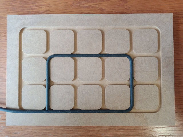
Small vacuum plate with a 6 mm foam rubber band. The band can be shortened for the right length. The hole for the vacuum tube is missing till now.
So I could not transfer the milling parameters to the large vacuum plate, otherwise this would take way too much time. Therefor, I again changed the milling settings. This time I decreased the size of the squares by 0.1 mm. By this, I was able to use the 6 mm mill and all paths were only processed once. The estimated time for the milling was 6 min and the real milling time was 11 minutes – great!
Here you can see the milling parameters I choose for both operations:
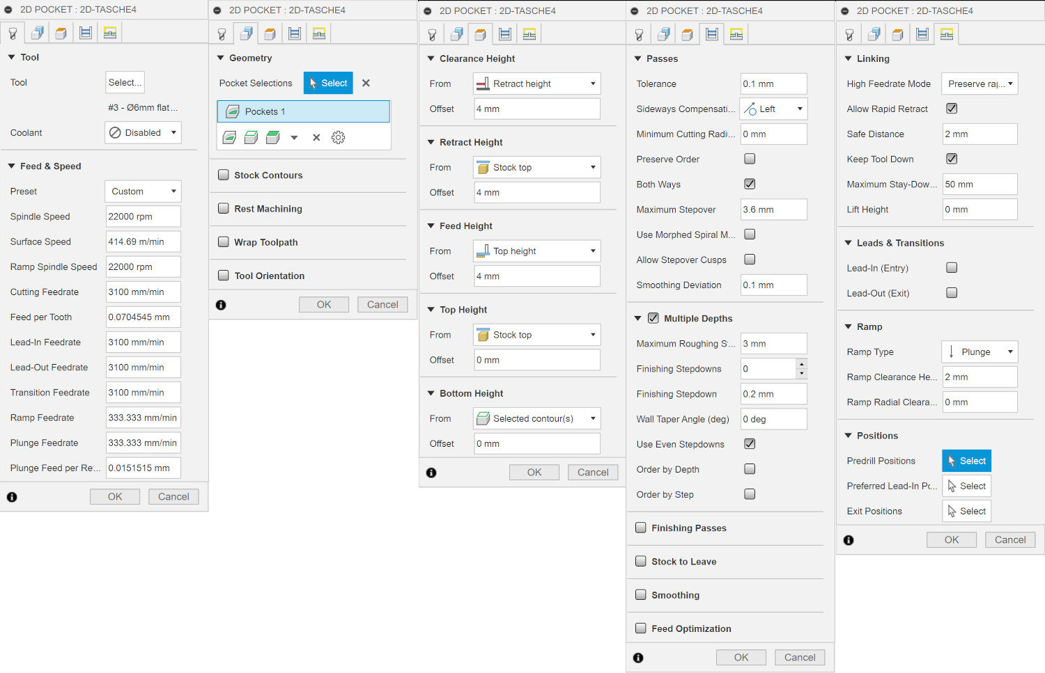
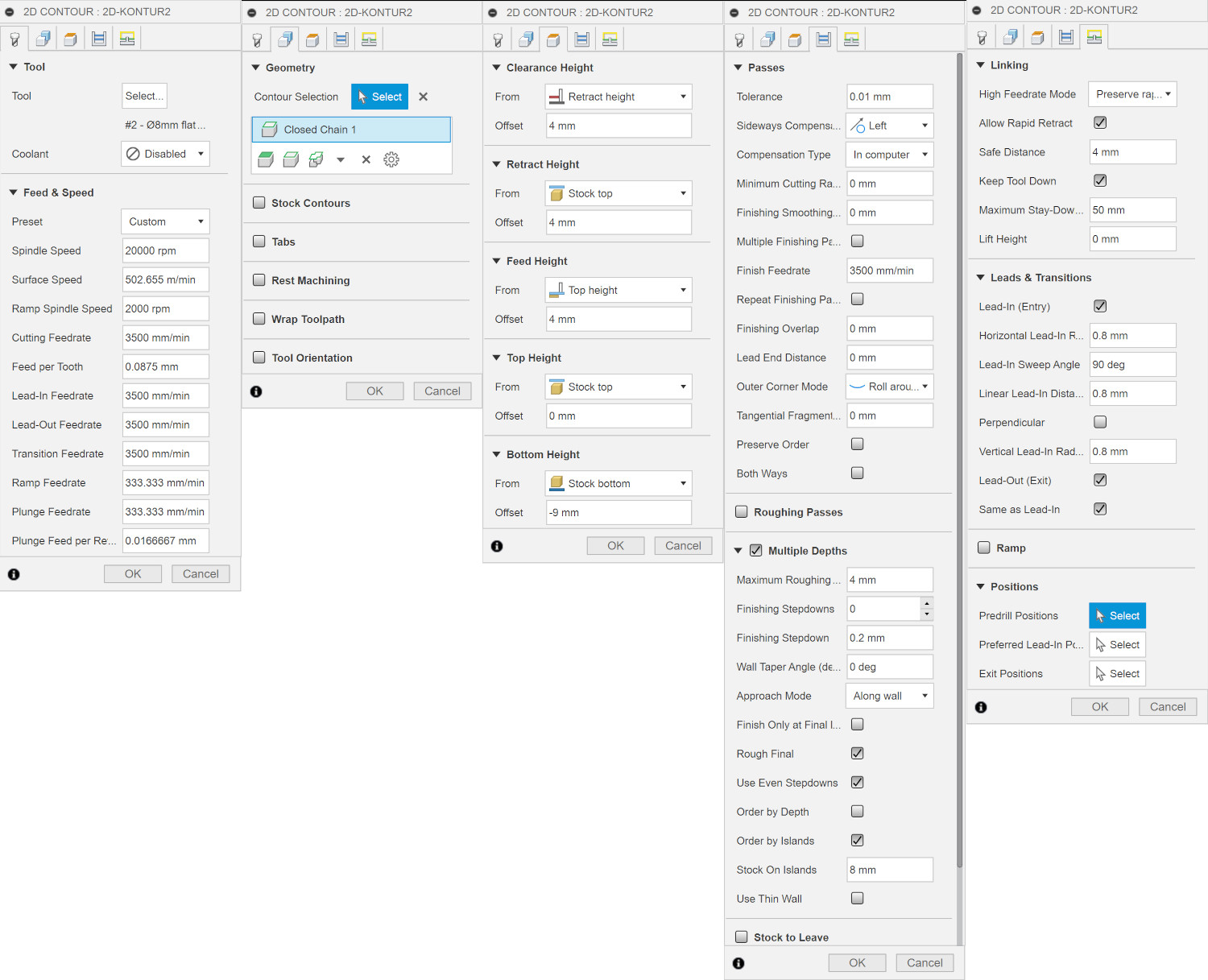
For the 2D pocket I selected a flat end mill with a 6 mm diameter. For all cutter, which are mounted to our CNC, the parameters under feed and speed are deposited in our Fusion 360 account of the HRW-Fablab. As geometry I picked the notches in the vacuum table. I reduced the retracted height to 4 mm to speed up the milling. I set the maximum roughing to 3 mm so that the cutter penetrates the material in steps of 3 mm (the half of its diameter). I clicked th checkbox “Keep Took Down” to speed up the milling. For the contour I selected a flat end mill with 8 mm diameter. As geometry I picked the outer contour of the vacuum table. I set the maximum roughing to 4 mm so that the cutter penetrates the material in steps of 4 mm (the half of its diameter). The rest of the settings was as described above.
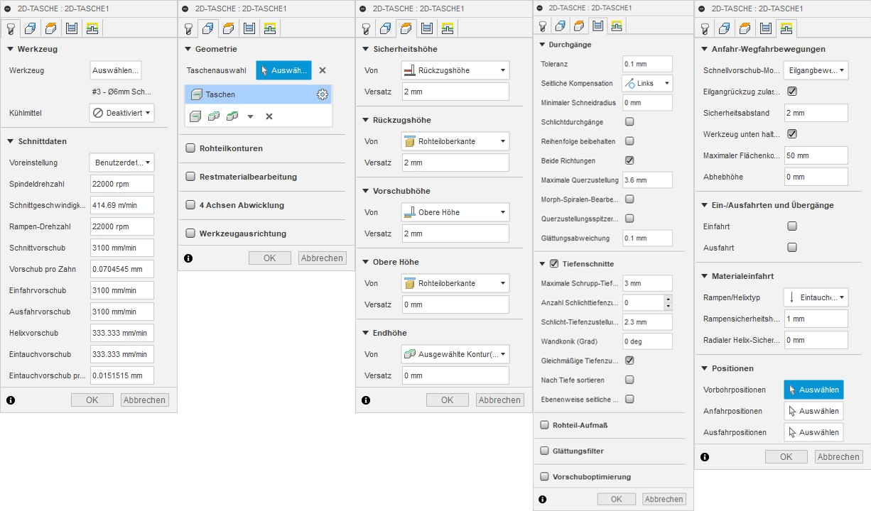
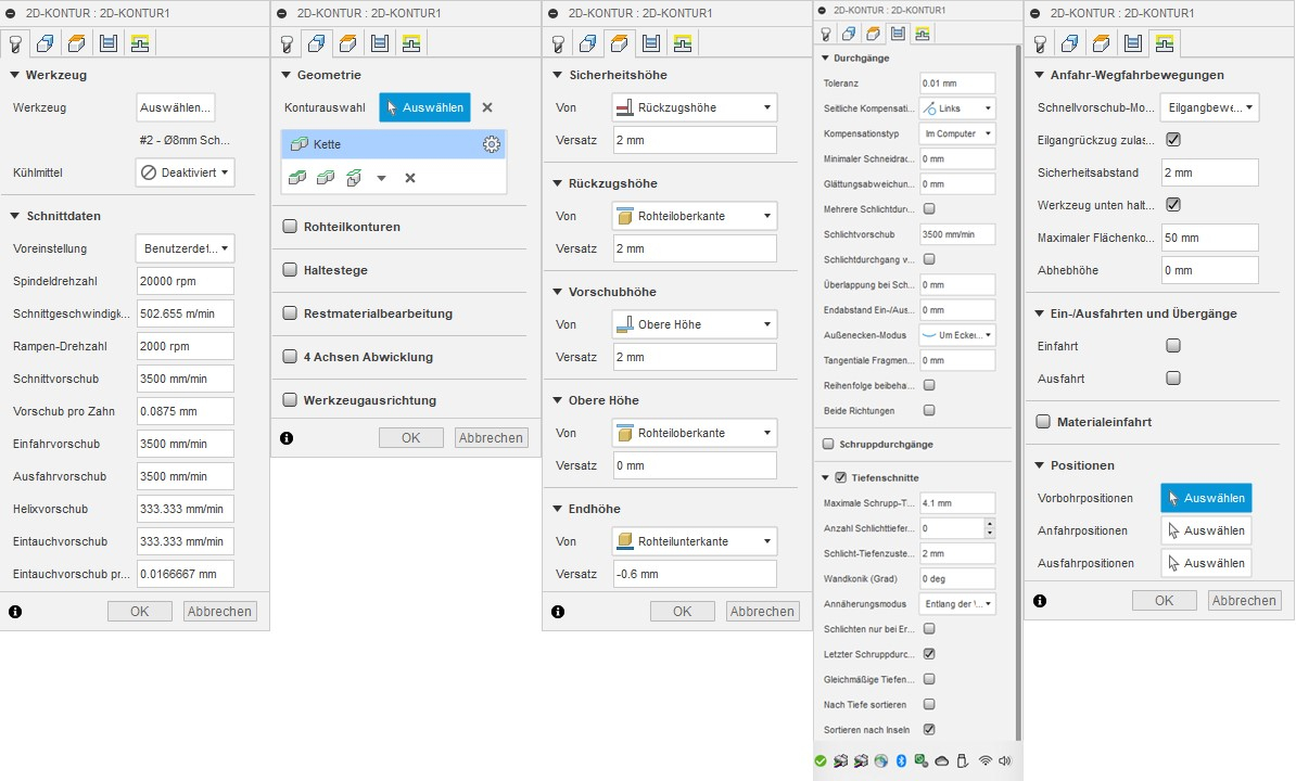
Here you can see the milling parameters I choose for both operations in German:
Here you see an image of the final large vacuum plate:
Here you can download the Fusion 360 files of the small and large vacuum plates:
large vacuum plate
small vacuum plate
Group assignment
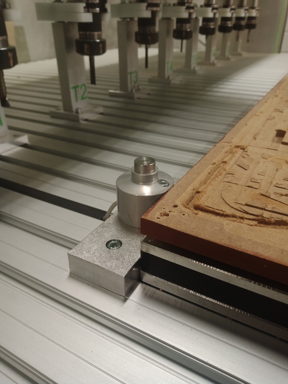
We are using a Versatil 2500 SB milling cutter:
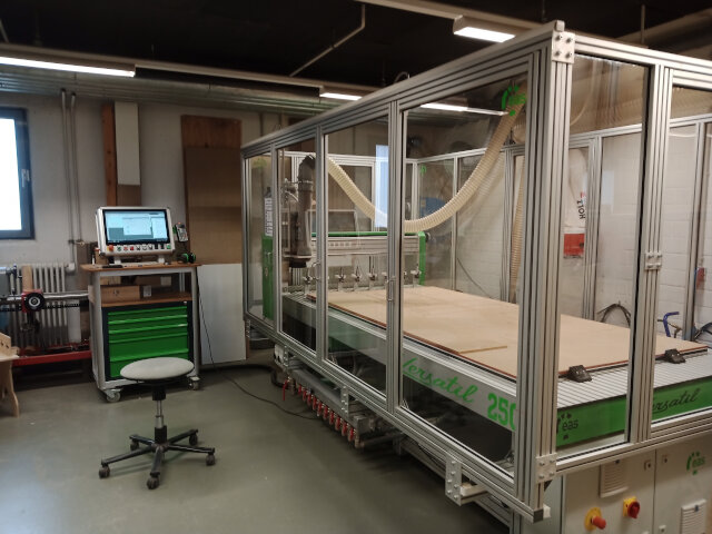
It has a full enclosure and you are not able to start the milling process until the enclosure is closed. The enclosure presents injuries from parts flying around and you can not reach into the milling cutter without opening it and this is not possible until you turn off the milling cutter. When the CNC is working you have to wear ear protection.
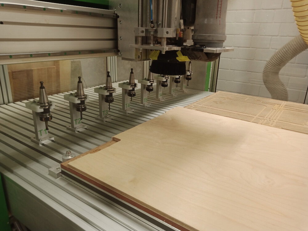
For the mounting of the plates we use a vacuum table. A small plate I also fixed with wood screws on the sacrificial plate. We use MDF plates as sacrificial plates. The vacuum table is strong enough to fix the workpiece through the MDF plate. The milling cutter has an automatic tool changer for 10 tools and these tool we can directly select in Fusion 360 with the right milling parameters. For safety reasons the milling parameters should not be changed.
Here you find informations to the milling machine:
Technical data Versatil 2500 SB
Travelling distance: 2500mm x 1250mm (+1000mm swivel arm) x 170mm
Space requirement: 3000mm x 1650mm (+1000mm swivel arm) x 1600mm
Worktable height: 950mm
Passage height portal: 260mm
Weight: approx. 550kg
Drive: hardened ball screw
10mm pitch
Self-adjusting nut to reduce backlash
Linear axes: 2 ground rails and recirculating ball slides per axis
Stepper motors: 230 V 4A 900Ncm X+Y+Z axis
Accuracy: Max. Positioning error 0.1mm
Technical resolution 0.00625mm
Repeat accuracy +/- 0.025mm
Speed: 24,000mm/min (positioning)
To check if the speeds and feeds of our mill are set right, I recalculated these parameters.
Therefor, I used the formulars and values I found on the following webpage:
https://webseite.sorotec.de/download/fraesparameter/schnittwerte_en.pdf
The following formula is used to determine the speed:
n [rpm] = (vc [m/min] × 1000) / (3,14 × Ø d1 [mm])
with:
n = Speed of the milling cutter in rpm
vc = Cutting speed in m/min (for hard wood: 450 m/min)
d = Cutter diameter in mm
z = Number of teeth (in our case: 2)
fz = Tooth feed
vf = Feed rate in mm/min
speed:
450 x 1000 / 3.14 x 6 =
450.000/18.84 = 23,885 rpm
In Fusion 360 the speed was set to: 22.000, so its in the right range (a bit too low).
450 x 1000 / 3.14 x 8 =
450.000 / 25.12 = 17,914 rpm
In Fusion 360 the speed was set to: 20.000, so its in the right range (a bit too high).
The following formula is used to determine the feeding rate
vf = n × z × fz
feed:
22000 x 2 x 0,055 (for 6 mm) = 2,420 mm/min
In Fusion 360 the feed was set to 3100, which is much higher than my calculated value.
Presumably, my college calculated with soft and not hard wood.
20000 x 2 x 0,065 (for 8 mm) = 2,600 mm/min
In Fusion 360 the feed was set to 3500, which is much higher than my calculated value.
Presumably, my college calculated with soft and not hard wood.
I tested different feeds with the 8 mm mill: 3500, 3000, 2500, 2000 mm/min (top to bottom). But I could not see any differences in the cuts. So you can use the highest speed to mill faster. The kerf of all cuts is 8 mm wide.
Here you see a video of the cutting process
At the bottom of the page you can download the used files.
Following I describe the handling of our mill:
Wood plates have to be placed on the vacuum table aligned at the under left corner of the sacrificial plate.
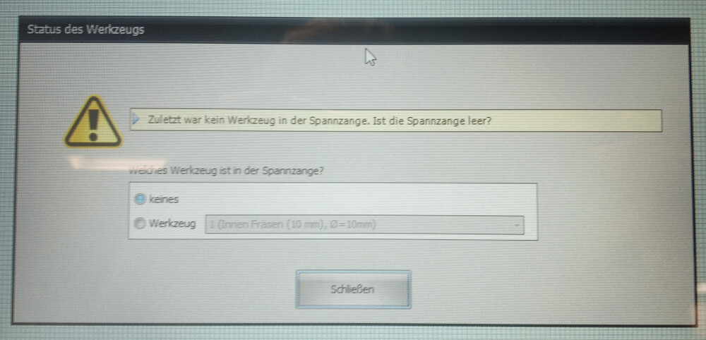
After opening the software (NC-EAS(Y) Pro) you will be asked if there is a mill in the milling cutter.
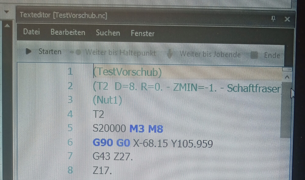
To start the vacuum with the milling process you have to manually add a M8 command after the M3 command. After that you have to save the G-code file.
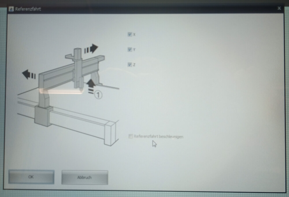
Then you have to perform a reference run.
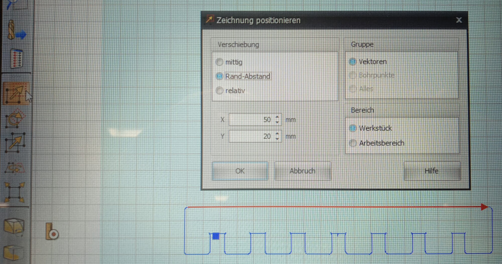
After opening the G-code you have to move it by at least 10x10 mm from the under left corner. In my case I moved it more, because the plate showed a hole at the under left corner.
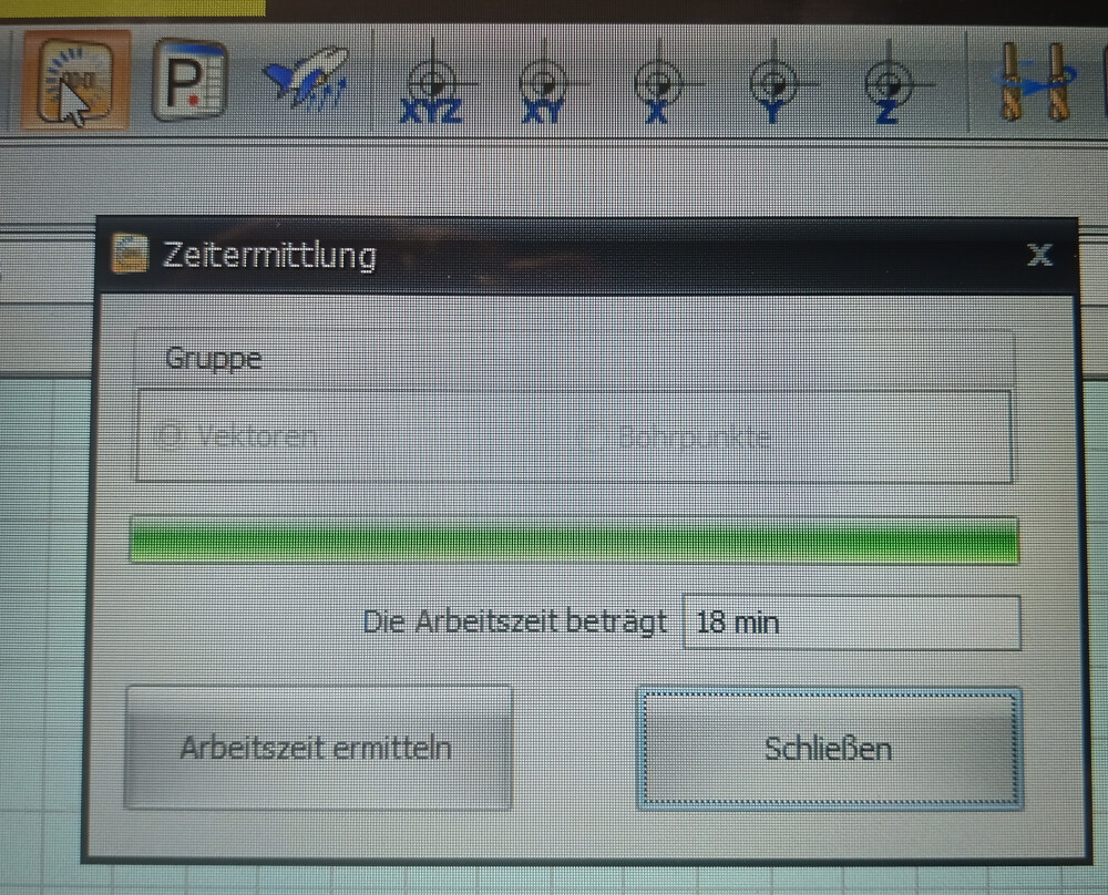
You can calculate the time the mill will need for the job, but the calculation is not that accuate.
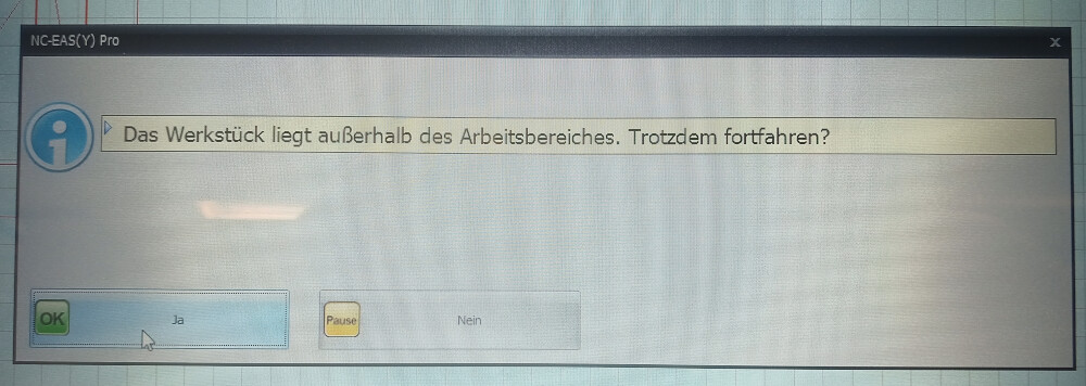
When you start the milling there is an error message that the plate is not placed correct. You can ignore this message and click yes.
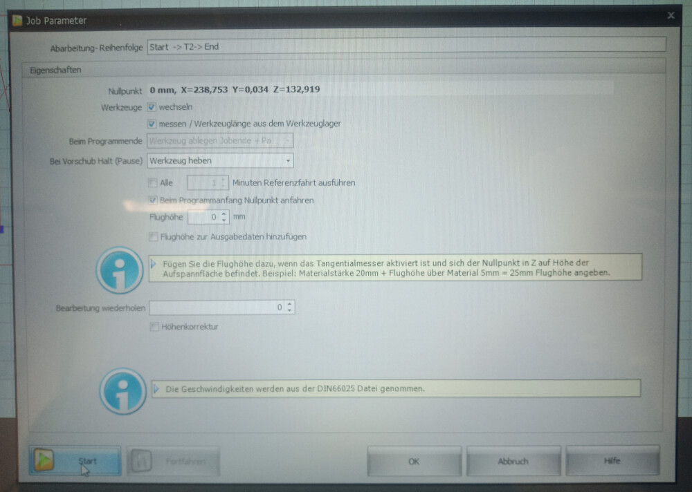
Then a window appears were you do not have to change anything. With the click on the Start button the milling will start.
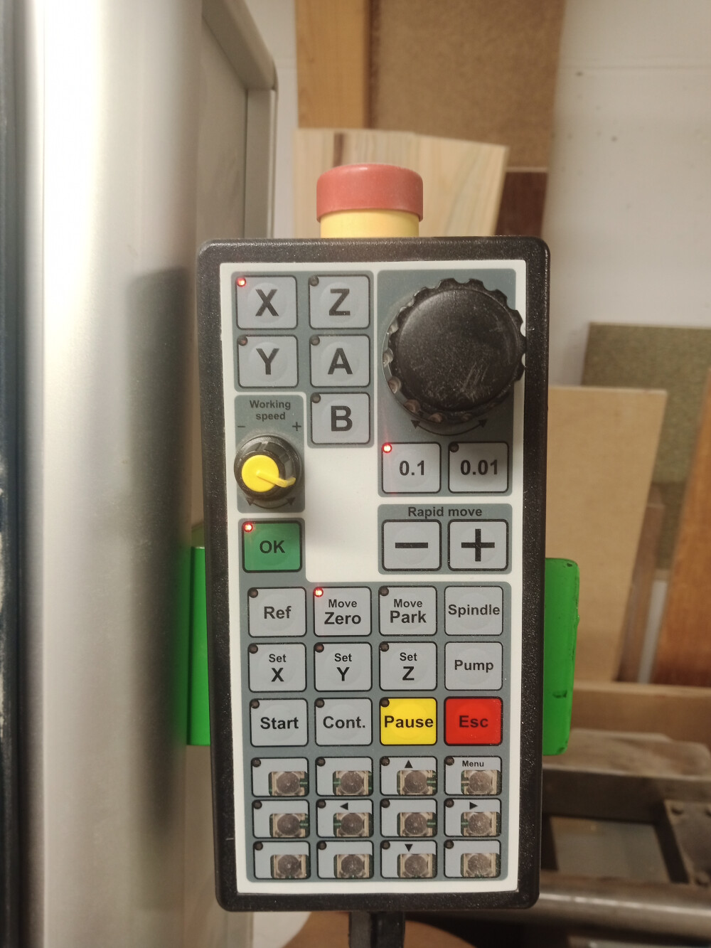
With this remote control you can pause or stop the milling process, if something wents wrong.
At the start of the milling process the mill is driven to this z-height buttom to adjust its height.
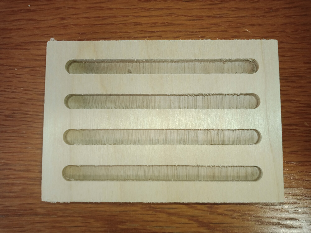
I milled a joint clearance test with the mill with a 4 mm mill. I choose this small mill so that the dogbones at the inner contour of the joints get not that large. The milling took quite long (about 30 min), because I had to use steps of 2 mm in Z-direction (half of the mill diameter). The joint in the centre has a width of 12 mm. To the sides they get bigger/smaller (12.72, 12.28, 12.24. 12.00, 11.76, 11.52, 11.28).
The joints in the middle fits best. But the plate was not exactly 12 mm thick, but 11,7 mm, so you should make the joints about 0,15 mm larger at each side to be sure that the pices fit together.
Here you see a video of the cutting process
Downdoads
jointClearanceFinal.stl
TestVorschubFinal.stl
TestVorschubFinal.f3d
jointClearanceFinal.f3d
jointClear.nc
TestVorschub.nc