3. Computer-Controlled Cutting
assignment
   group assignment:
      characterize your lasercutter's focus, power, speed, rate,
         kerf, joint clearance and types
   individual assignment:
      cut something on the vinylcutter
      design, lasercut, and document a parametric construction kit,
         accounting for the lasercutter kerf,
         which can be assembled in multiple ways,
         and for extra credit include elements that aren't flat
individual assignment
This week I wanted to build a lasercutted box, which can be used similar as the boxes in the morph3dbot environment (https://morph3dbot.de/) or the UC2 environment (https://github.com/openUC2/UC2-GIT).
In these environments the cubes are 3D printed or injection moulded, but 3D printing takes quite long and only a few fablabs have an injection moulding machine, so I thought it would be beneficial if there is also an environment with cubes you can lasercut.
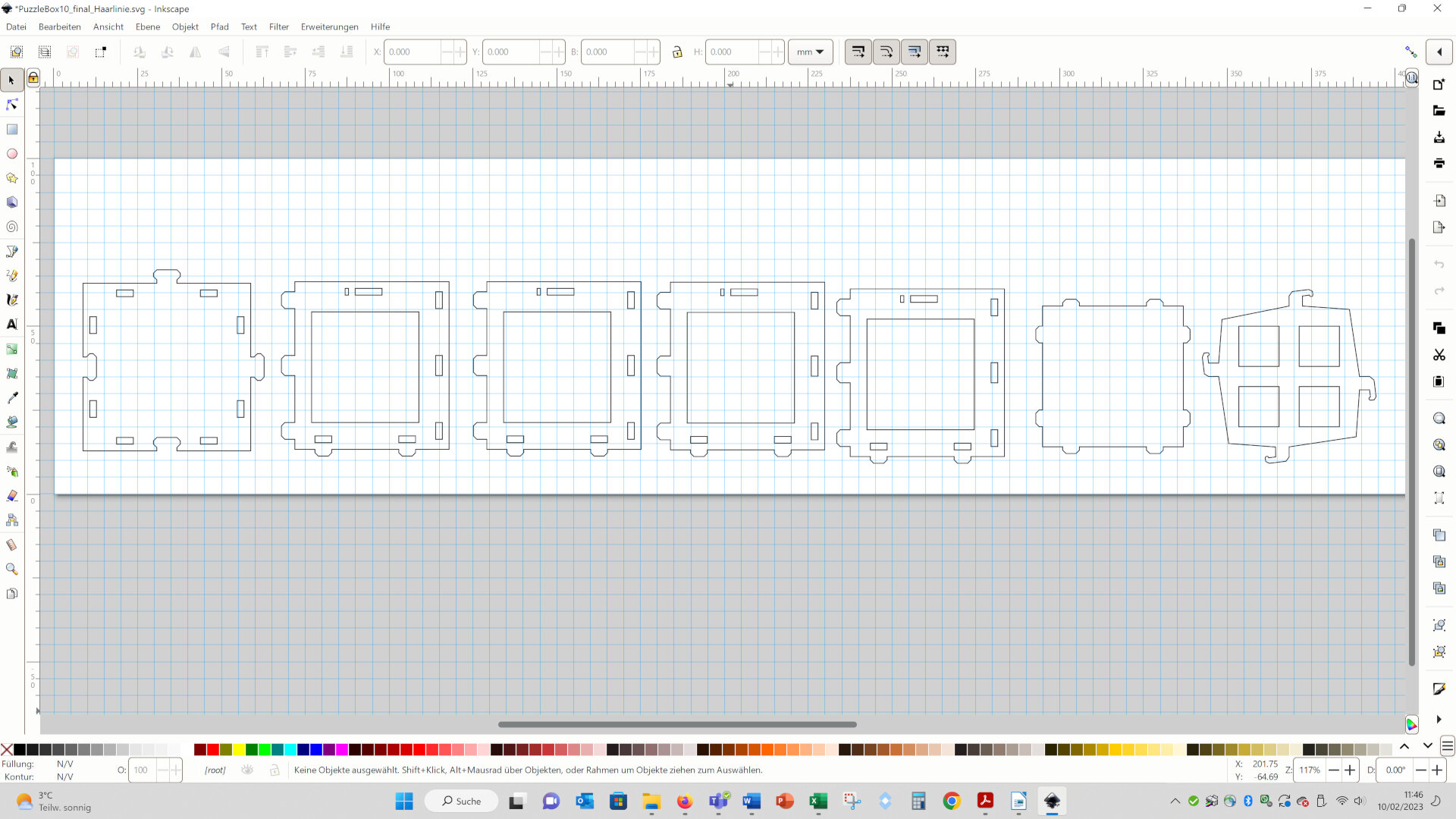
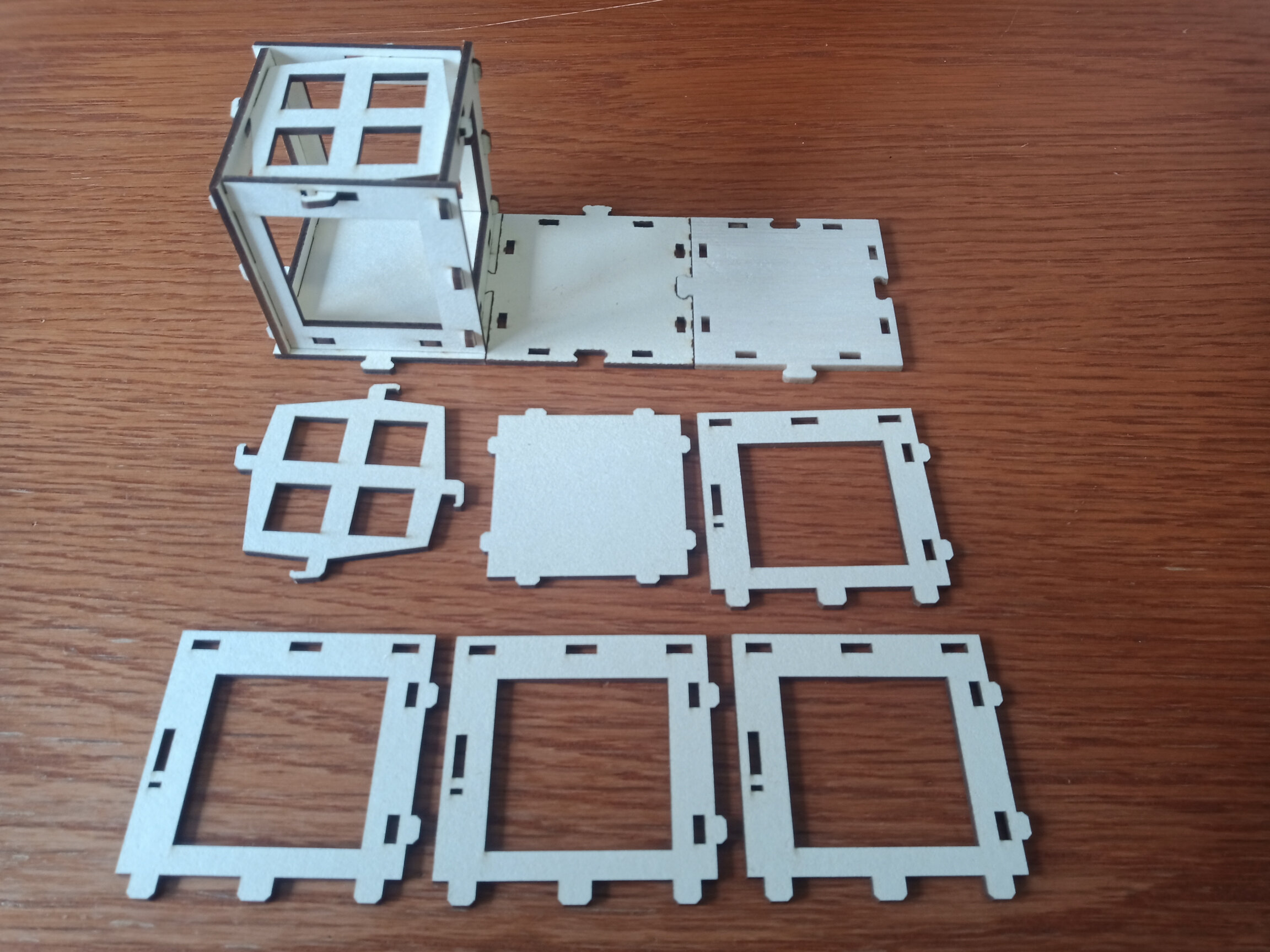
I designed the geometries in Inkscape. The cube consist of a bottom (second from the right), four equal sides (second from the left...) and a top (right). Further, I designed a baseplate (left), which you can extend with puzzle joints and on which you can arrange the cubes.
For designing I used the grid and the snapping function of Inkscape. This simplified the design process a lot!
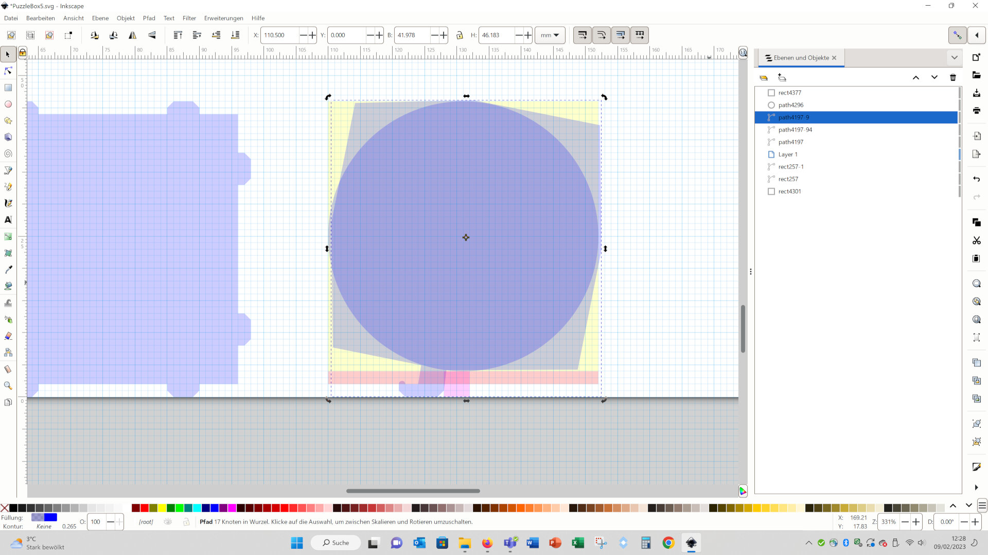
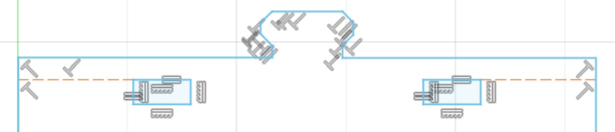
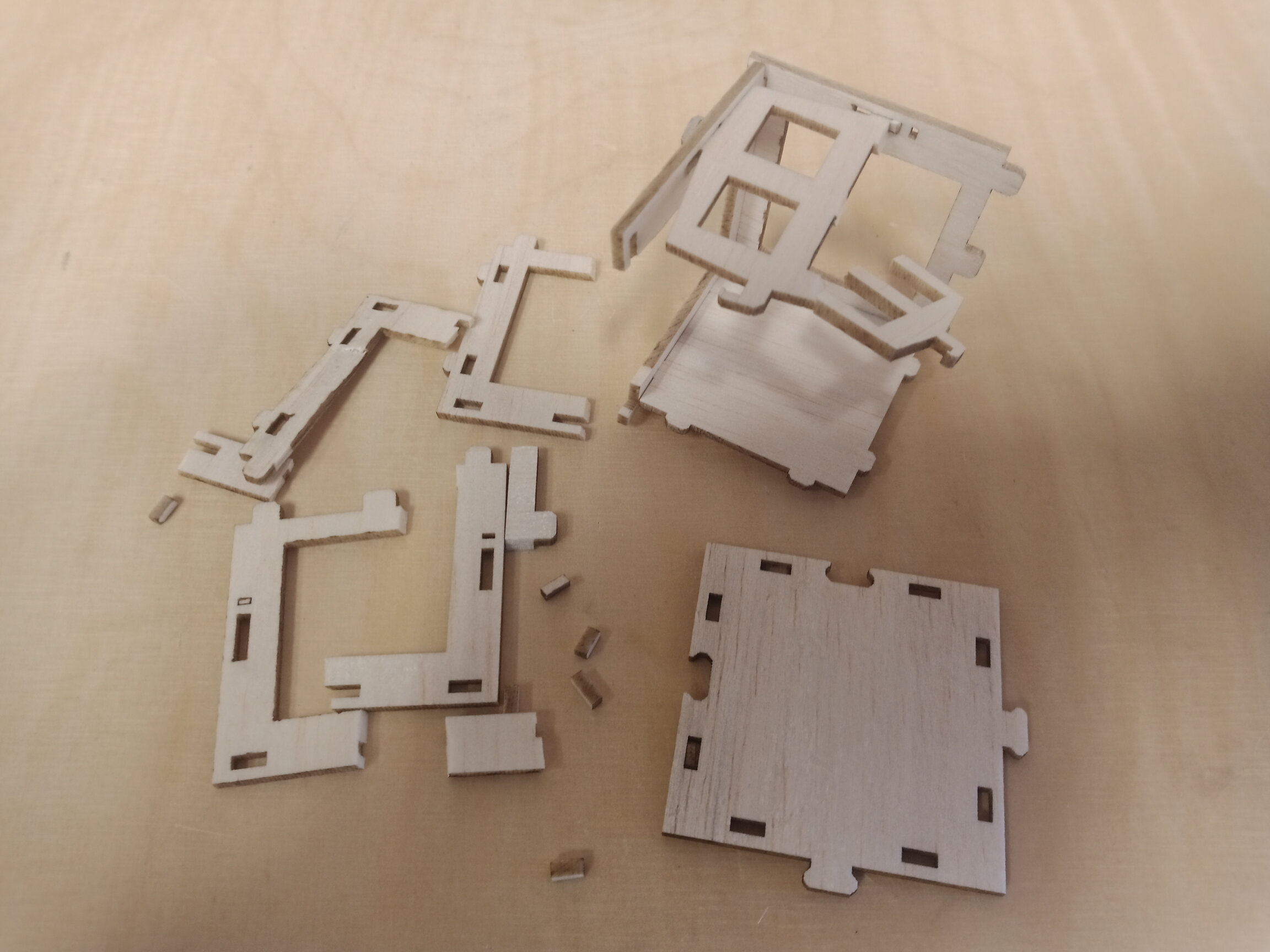
All parts of the cubes should be locked by the top of the cube. Therefor, I designed a snapping mechanism, which should lock all parts in place when turned by about 7 degree. In the following picture you see a intermediate state in the design process of the top:
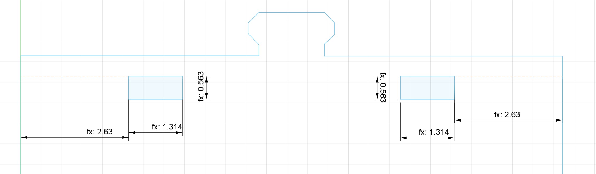
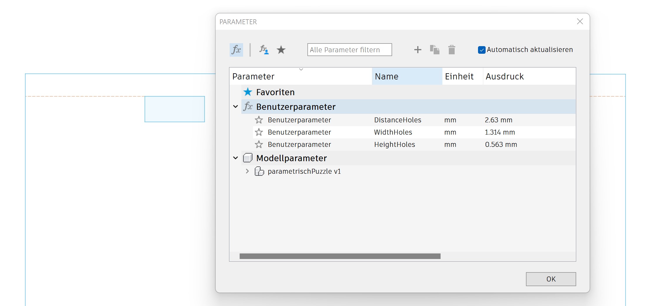
Later I added parameters using the provided parameter function in fusion. I added three parameters: one for the distance of the wholes to the outer corner, one for the width of the wholes and one for the height of the wholes:
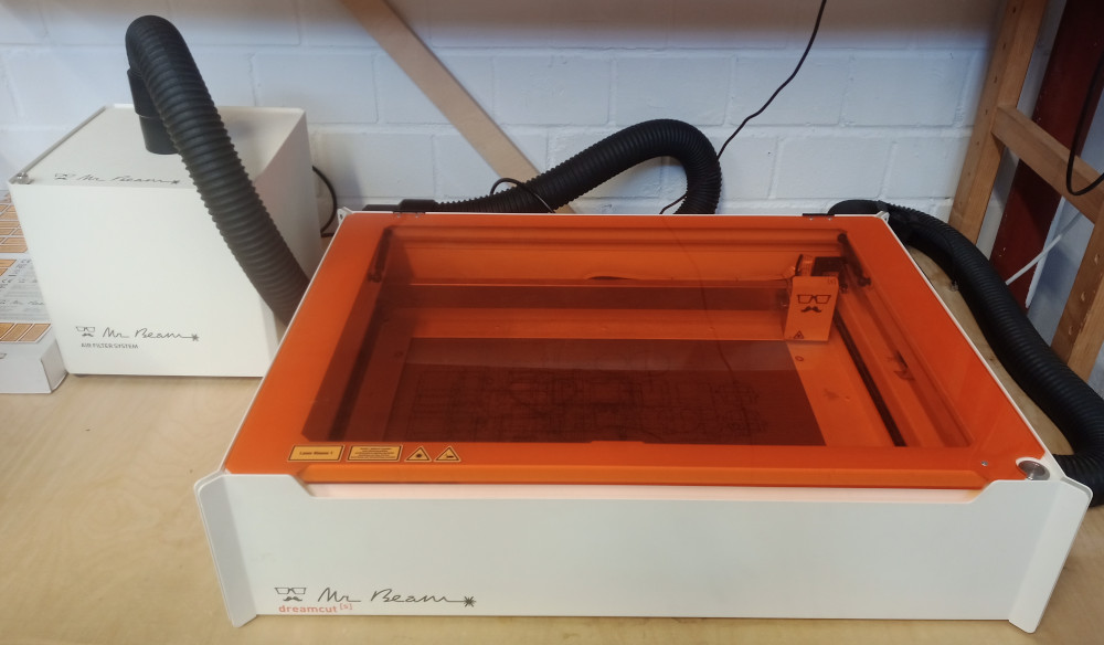
I used the lasercutter Mr. Beam (50x39 cm work space, CO2, 5 watt, see image below).
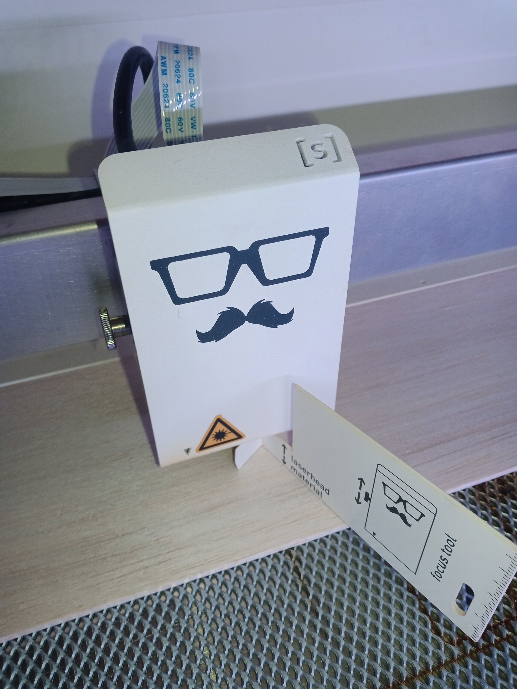
 To adjust the focus of the laser
you simply have to adjust the height of the laserhead, so that a
cardboard tool fits under the laserhead:
To adjust the focus of the laser
you simply have to adjust the height of the laserhead, so that a
cardboard tool fits under the laserhead:
First I cut all parts out of 2 mm thick balsa wood with the given parameters for balsa wood of this thickness:

But the balsa wood was way too fragile:
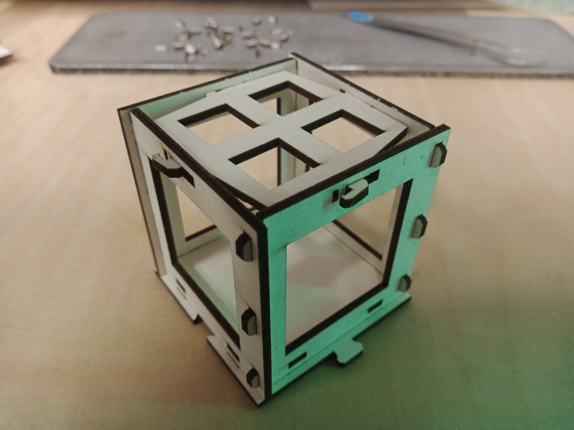
Then I cut all parts out of 2 mm finnpappe. In the software of Mr. Beam there were only parameters for 3 mm thick finnpappe. This parameter intend that the laser makes three iterations. So I adjusted this parameter from 3 to 2 (to consider the lower thickness of 2 instead of 3 mm). With these parameters the laser cut very well through the 2 mm finnpappe and this material is much more robust, so I could assemble the cube:
In the further development I will adjust the hooks to snap into the holes for a better fit and I want to add slots on the upper edges of the sides, so that you can stack the cubes over each other.
Here you can see one cube placed on a bottom plate, one cube in individual parts and how you can expand the bottom plates with puzzle joints:
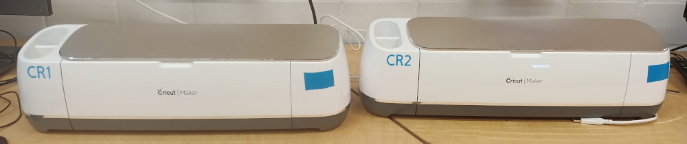
Out of vinyl I cut a heard with a slightly adjusted nice quote. I created the design in Inkscape, cut it with a "Cricut Maker" (see image below) with the standard setting for vinly and applied the foil on a glass jar. The Cricut Maker can cut designs up to a size of about 29x59 cm. The maximal cutting speed is 4 inches per second.
Here you find an explanation on how to upload .svg files to the Cricut design space:
https://www.youtube.com/watch?v=EsOht625CnI
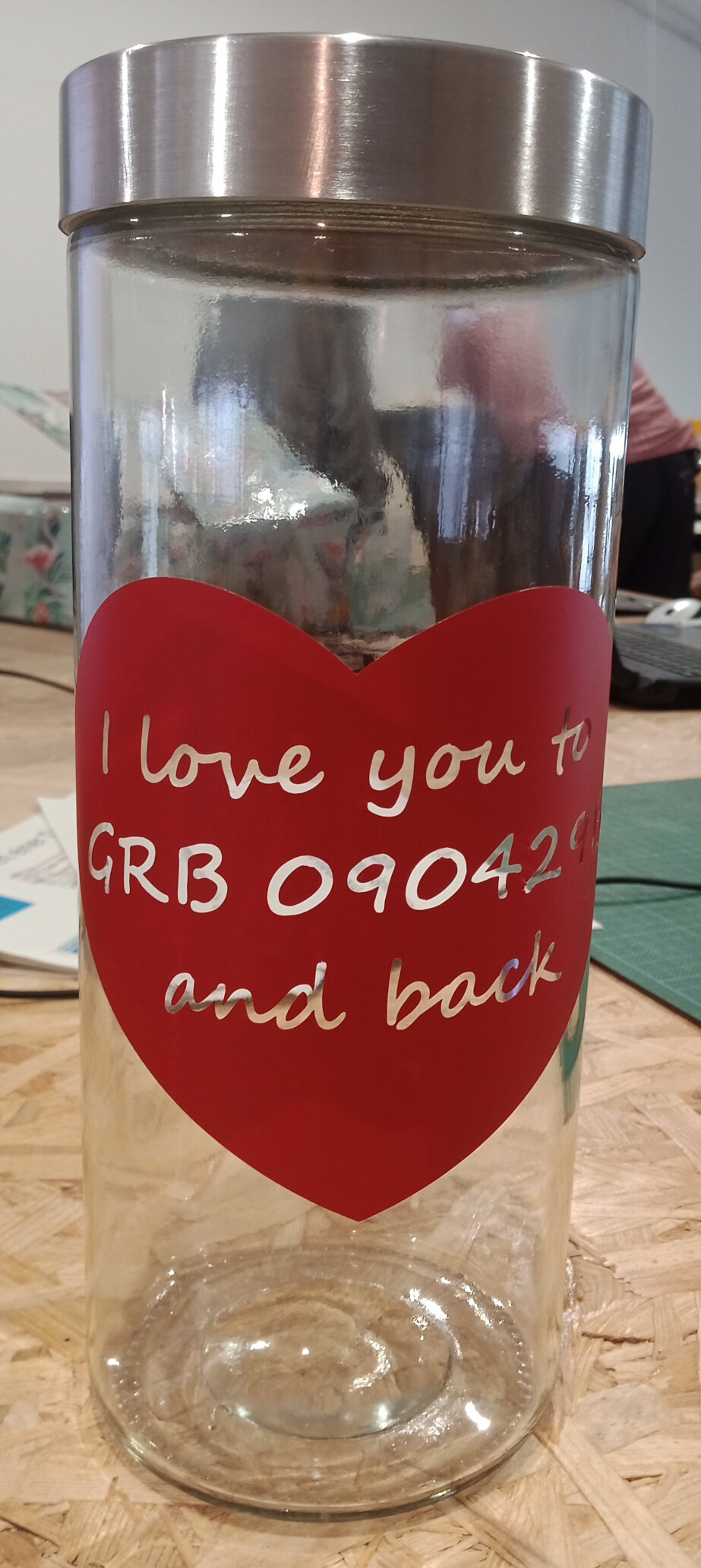
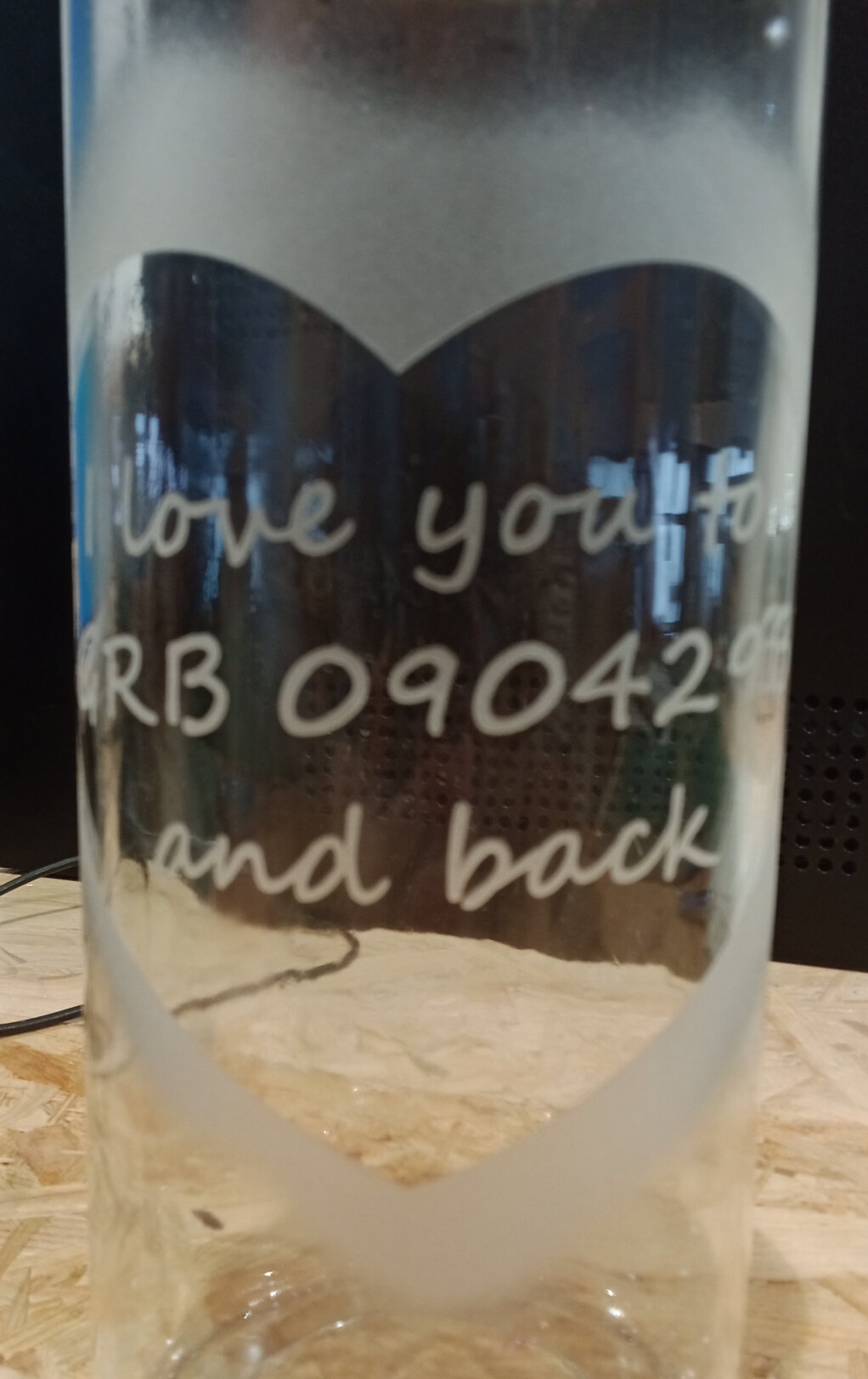
Left: the jar with vinyl, right: after sandblasting the letters were engraved into the glass jar.
I gave the vessel to my fiancée.
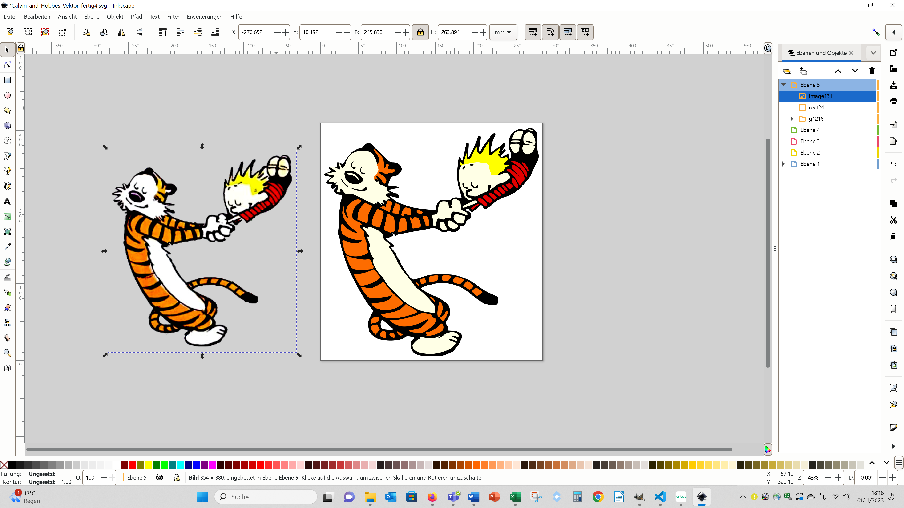
Further I cut an image for my niece. First, I vektorised the image:
Then I imported the single layers in Cricut Design Space:
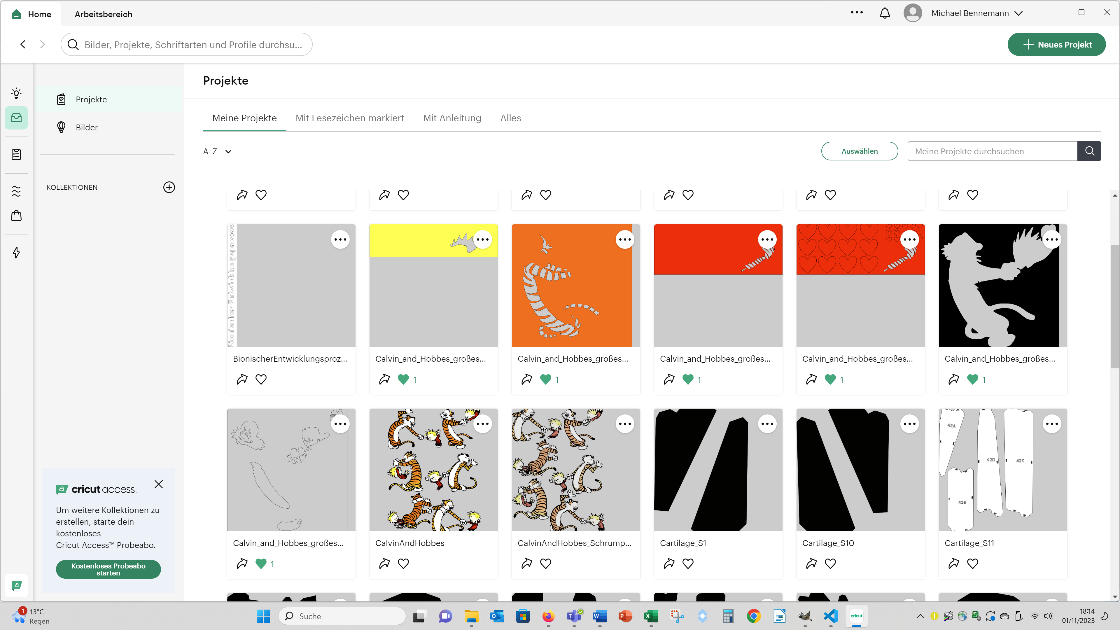
Then I cut out the different layer out of different coloured vinyl foils with the standard settings for vinly foil:
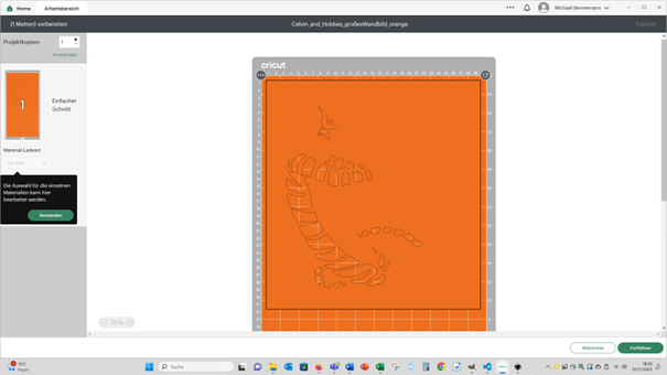
And finaly I put the different vinly foils on top of each other:
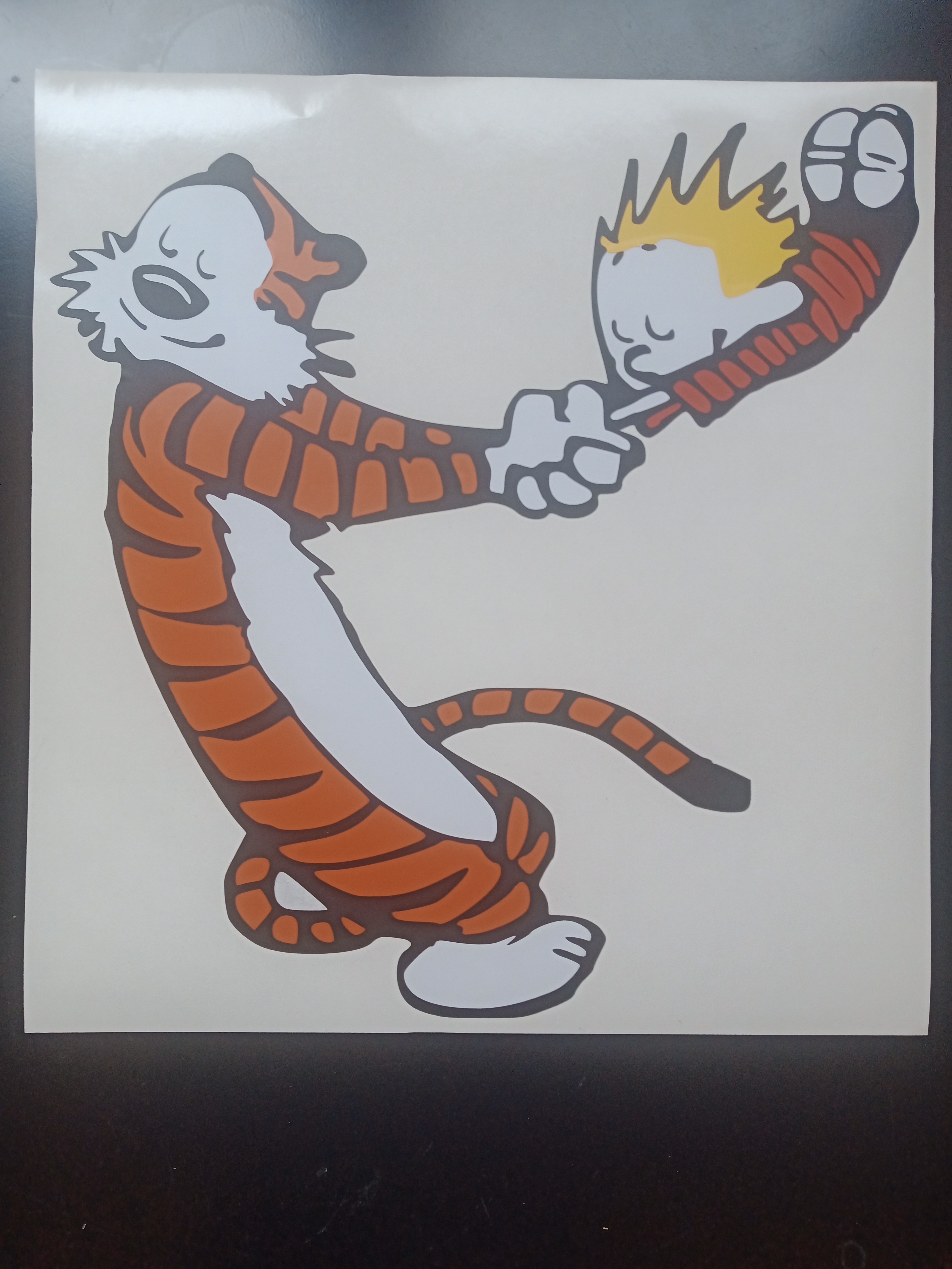
I cannot provide the svg files here as I do not have the rights of the images.
group assignment
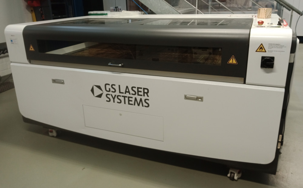
For the group assignment I compiled a vector graphic, with which you can figure out the best parameters to cut and engrave using your second lasercutter (GS Laser Systems (GS 100160 Pure) 100x160 cm workspace, CO2, 150 watt, see image below):
Here you can download the .svg file to test the envgraving parameters:
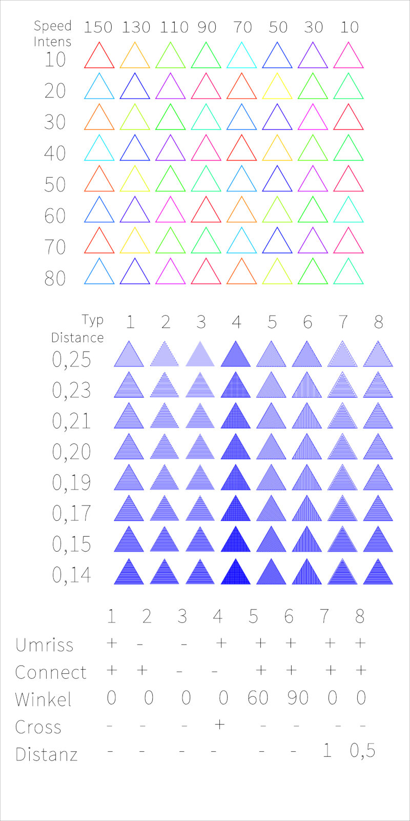
With the first square you can test the best cutting and
engraving parameters concerning speed and intensity. And with the
second square you can test the best engraving parameters
concerning the distance of the lines, with or without contour,
angle of the lines and some more parameters.
I had to adjust the svg to test the parameters, because you can only use 20 different laser cutting settings in one cut.
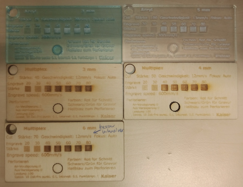
Here you see the results of these tests. On the left the laser is out of focus. With the laser unfocussed the kerf was much brider and the lasercutter did not cut throgh the acrylic. I defocused the laser by focusing it and moving the laser a bit away from the surface.
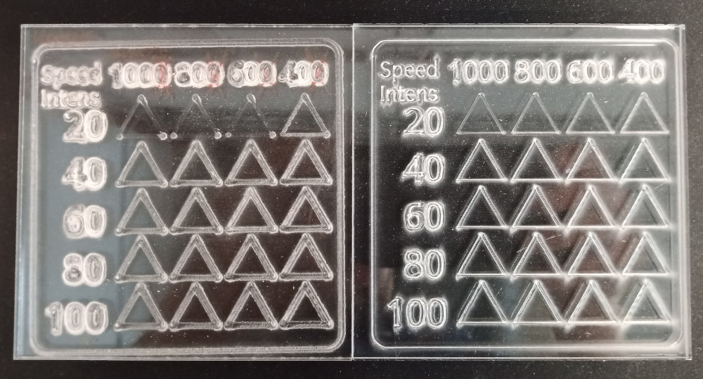
The tests were performed with speeds of 100 to 40 mm/s and intensities of 20 to 100%. The best parameters for our laser to engrave 5 mm thick acrylic are 100% intensitiy and a speed of about 30 mm/s. To cut 5 mm thick acrylic we use also 100% intensity and a speed of 13 mm/sec. Here you can download the adjustet .svg file to test the envgraving parameters:
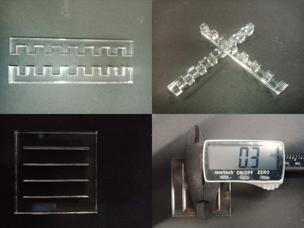
In the following images you see the results of ours tests concering the kerf, frequency and the joint clearance of our laser cutter. For the joint clearance test I cut different sized grooves (from 4.7mm to 5.3mm) into a 5 mm thick acrylic plate. The grooves with a size of 4.9 each fit best, indicating, that out lascutters kerf is about 0.1 wide. I also tried to measure it with a caliper, but its difficult to distinguish cut and meldted acrylic. I also cut 4 lines with different frequencies (500, 1000, 2500, 5000 Hz), but I could not see a difference. Maybe the surfaces of the cuts with lower frequencies are rougher than these ones with the higher frequency. 5000 Hz is the standard setting of our laser cutter to cut acrylic.
Here you can download the .svg file to test the joint clearance parameters:
In the following image you find parameters for the GS Laser, which were determinded by my HRW-Fablab collegues, ealier.